Test of digital I/o
Hello
Could someone please see the/explain how I would get an entry port to light a lamp in labview. He 8 switches I need to turn it on. I'm confused how to convert digital true false? I have attached my VI and the picture of the physical installation
See you soon
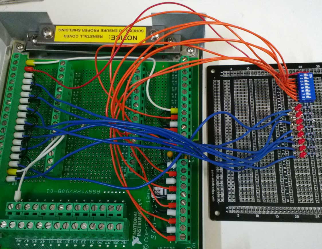
It seems that your "Digitalin" task is configured to read all of the port. So, you will get a 8-bit number representing all 8 lines of the port.
You can convert the number in an array of Boolean and then index on each line.

Tags: NI Software
Similar Questions
-
Where can I get a pdf of the sample to test the digital signature?
I'm testing my digital signatures in Adobe Reader X on Windows. However, I can't find a PDF file that has the "correct" rights for me to sign.
Y at - it somewhere that I can get an example of PDF file that will allow me to try my digital signature?
And here's one: https://workspaces.acrobat.com/?d=wdmk-UM-PE35I3UdLukz9g
-
Hi all
I have a question about multiple digital limit test.
My data source is a table tab1 [].
I need to compare each item of tab1 [] with the element that is associated with another table tab2 [].
In other words, I would like to check the weather tab1 [i] > tab2 [i] (for i = 0; i > 32; i ++)
Simple problem isn't? However, I can't find any effective solution to specify my expression "Low Limit"! ^^
To be more precise, I would say I want to create different expressions "Low Limit" 32 (Low Limit A = tab2 [0] , low limit B = tab2 [1], etc. would be a bad solution). I would like to create an expression that would be able to handle all of the comparisons. Is this possible?
Thank you very much for any help!
I think that the best thing to do in this case would be to use a regular step numerical limit with the parameters of the activated loop. Your data source would be set to something like:
Locals.tab1 [RunState.LoopIndex]
And the type of comparison would be GT with the low limit:
Locals.tab2 [RunState.LoopIndex]
You can set the parameters of the loop on "Fixed number of loops" stage with 32, or you can use the custom loop type based on a fixed number of loops with the expression of loop while the value to something like:
RunState.LoopIndex<>
Hope this helps,
-Doug
-
No puedo mandar una salida test panel digital desde el
Buenas tardes
El reason del present mail are para su request apoyo para resolver una duda tengo, using el test me panel led MAX, una tarjeta NI PXI 6527, mando a iniciar (Start button) the prueba una SCB-100 using y estoy conectado has linea 0 del puerto 3, not pine 97 (P3.0 +) y 98 (P3.0-) are una salida digital , hago los botones 'All top' click y 'All down' pero no nada obtengo has digital output, las tickets if las puedo leer desde el panel test, tambien me do good + 5v y GND.
I want to connect a led of color rojo como indicator signal pero nor even obtengo una Señal.
The favor su apoyo pido
Saludos cordial
Buenos Dias, Rafael,
Me designed that are MAX a self-test, esto hiciste en el para poder saber if you componente esta in buen estado. If you llegara a dar como resultado as no lo pasa ahi tendriamos problemas.
Sin embargo, no creo as you sea este caso, todas maneras No debes pasar por el alto hacer esta prueba.
MAS especificamente sober lo as our questions, esta tarjeta tiene relevadores estado solido, por lo as the conexion no can be directa.
In estos links to habla a sober poquito como hacer las conexiones para una Señal TTL handle, not con the cual no tendrias problemas para poder encender UN LED.
http://digital.NI.com/public.nsf/allkb/209FA5B16C73E19B86256D9F00764B63
http://digital.NI.com/public.nsf/allkb/3D591888EB53A7CE86256D1F0001AEE3
In the first liga tiene una liga al manual dentro y on page 3-11 viene UN esquematico. Intentalo, No debes tener of any lost.
If siguieras having algun problema are some screws para poder test you tarjeta, aqui you mando the address of uno.
http://zone.NI.com/DevZone/CDA/EPD/p/ID/4841
Finalmente, if not our dio nada esto pero aun no connect el is can be LED, is a tool in the page nor para diagnosticar if you card is encuentra in buen estado.
Lama's Diagnostic Utility, the liga esta aqui y you tarjeta if soportada esta para esta application:
http://Joule.NI.com/nidu/CDs/view/p/ID/2244/lang/en
Saludos, y Exito en you application.
-
Multiple TestStand limited digital test next tep
I am a multiple test limits digital step stype of coding and I have a fundamental question/problem that I don't see a simple solution to. If I'm measuring and comparing 4 differnet settings, I have 4 different steps to guide out of depending on the result. How you code this optimal in Teststand?
It is excellent. Thank you very much.
-
To a result NULL of Labview TestStand to a type of digital test limit.
Hello:
I am looking for a way to pass a null value as a result in a limit test multiple digital test type. My tests are written in Labview.
The tests now pass a value of '-' 999 to TestStand to signify that this measure has not been made, but this requires additional processing and code in our data analysis tools. Passing a value zero would simplify the tool and reduce the workload.
Thank you
Mike
You can switch NaN instead. At least, I think you can. TestStand supports NaN, but I never spent through Labview adapter, so I'm not 100% sure if it will work. NaN is treated in tests limits labview as follows (hat tip to James Grey here):
(NAN > x) == false
(NAN == x) == false
(NAN< x)="=">
(NAN == NAN) == trueI don't know how it would be dealt with when writing a good database. I guess it depends on the data base and values of what digital special supports. A quick search shows that NAN (not sure if he would lift an error or that) does not support Sybase, MySQL stores NAN as NULL in numeric fields, SQLite stores NAN as a special string code, Access stores in the form of NAN.
So you should always write a step for translate NAN for NULL values, but I think it would be easier to write and maintain than an arbitrary number.
-
Output digital USB 6008 when connected does not
Hi, I have an external circuit and I want to control it using materials DAQ 6008 / using LabView, I tested the digital port work (giving me 5V) but once I connect it to my circuit (PIC16f887) pin his Gimme 0V, I do not know why
Hello
because the NOR-6008 has an exit open collecor must connect a pull up resistor to + 5V.

-
Digital input and output problem
Hello:
I do a test for digital i/o:
for a table of the digital signal to an output of data acquisition in the digital input to detect the output signal.
(bascially, it's like a loop that goes outside the material)It's pretty simple, as shown in the attached fichier_1.
It works well.
The manual light switch controls, which means that inputs and outputs are ok.Then I went on the low level DAQ for better speed, as in attached fichier_2.
But it does not work. Especially when I pressed stop to abort the loop, an error has occurred:To speed up, I went to the low-level data acquisition as the fichier_2 attached.
But it does not work. Espeically when I press the "stop"button to exit the loop, the error occurs.Possible reasons:
Requested value is not supported for this property value.
The value of the property may be invalid because it is in conflict with another property.Property: SampTimingType
Asked the value large clock
You can select: on requestI don't understand why the sampling time has a conflict here.
(It is probably just something very simple in data acquisition, but I checked a few examples and did not find a clue).
Hope someone can give me a suggestion.Ultimately, my goal is to make the attached file_3.
In this one, I generate a digital output, and then lead to the entrance.
Then I can take it as a signal to trigger my other task.Note:
I use a similar conti signal to control one of my camera.
I need to sync it with my another task.
So I think to generate a digital output (which share the same clock as the signal similar to the data acquisition device), then put it in one of the digital input.
By detecting this digital input, I can trigger my task and synchronize with this signal similar.
My camera's USB-6211.
I am aware of the latency of USB, but once the value is a constant value, then the synchronization is always good for me.
Actually, I was using an analogue at the entrance of the to do it before, it may work, but the synchronization error is too big for me.
I need to do some calculations/judgment for this analog value, which makes the time difference varies.
So I'm trying digital entry now and I hope that the digital input can trigger my task with a stable latency.Thank you very much
Have you looked at the specs? It clearly states that the digital I/o is a programmed software. You have not any hardware clock at all. The best rate that you could possibly achieve is around 1 kHz and which would have a considerable jitter the nature of non-determimistic of windows.
-
Configurable custom test types
Hello
I'm doing a type of custom step that works like the limit works in test limit digital ex.. What I want, is a new component called "Test" with 1 field shall be amended by the insertion of a variable or just an exodus of value 2 as you can do within the limits of Tap, I did a step where you can change this by clicking on a button that opens a LabVIEW vi and from there you can change I'm looking for is to make sure you can change it without having to open LabVIEW test bench as well so that you can insert a variable...
Attached is a picture showing what I want...
Marck H Hansen
Marck Hello,
At the moment there is no official support for this feature.
I recommend to visit this idea http://forums.ni.com/t5/NI-TestStand-Idea-Exchange/Ability-to-create-user-built-in-StepTypes/idi-p/1...
and fire a kudo to her...
Concerning
Jürgen
-
DAQmx write (digital) works in mode "highlight execution", and not in normal mode
Hello!
I would like to create a simple vi (it will work as a Subvi watchdog in a project) to send TTL 5V 0V 3 seconds 3 seconds, by performing an iteration in a loop.
Use a card PCI-6703 to that effect (beside that I use for the generation of analog static waveform on several stations). I also have a DAQ USB6212 card, and I have test my digital output with this USB card digital input via MAX.
The strange thing is that when I run my code in mode "highlight execution", I get what I want: 5V 3 seconds, 3 seconds, 0V, iteration.
When I try to start it in 'normal' mode, I only see the 5V constantly from the output through my digital entry in MAX.
I know I'm doing something wrong, but no idea what...
Please find attached the vi simple.
Thanks in advance!
Kind regards
Your overall loop time is 3 seconds (3000 MS of waiting). You have a 3 second delay between writing the real and write the value false. But as soon as the false is written, the loop reminds immediately (the second set of 3 waiting operates in parallel to the writing-Delay-Write sequence) so the real gets drafted immediately after the fake. It will be just a blip. So that if you run in the execution of climax, the code goes pretty slowly so that you see the Boolean value False as LabVIEW takes his time data flowing drawing wires.
Put a delay function after your DAQmx write wrong, as well.
-
Digital triggering PCI-6024E problem
In my view, the PCI-6024E is intended to support that integrates digital triggering. However, I get the following message if poster every time I try a digital triggering:
"Error-200452 is produced in property Node DAQmx trigger (arg 1) in DAQmx Start Trigger (PowerPlay) .vi:1-> relaxing test.vi.
Possible reasons:
Vital statistics: Property specified is not supported by the device or is not applicable to the task.
Property: Start.TrigType
"Task name: _unnamedTask<245>"
I'm on 8.9 DAQmx and Labview 8.6.
I've included the simple vi, I tried to test a digital triggering with where I made some stupid mistakes.
Thank you!
Hey Ptuinluff,
Have a look here for information and an example on how to use another subsystem to allow the trigger to start. Let me know if you have any questions.
John S
Technical sales engineer
National Instruments
-
Alienware m17x R4 Digital Out question
For a long time, I had a problem with my digital output. I can't really 5.1 audio on my computer even when it is plugged into my audio receiver. I have the Sound Blaster Recon 3Di, but there is no option to set the DTS or the sound of doby. If I go to playback devices and click on properties, I test Dolby digital, and I hear all the speakers work. But the sound-blaster software does not work unless I chose to play stereo sound to the digital way. Can I get the front speakers. 5.1 selected with the sound-blaster software give me only the front speakers. It seems that it is only play stereo no matter what camera I have set for the sound, speakers, digital output or my TV.
I guess that the sound blaster software has no opportunity to tell pilots to use 5.1 instead of stereo. I use Windows 8.1, but I think that it does the same thing, even when I was with Windows 7. In the channel mixer adjustment menu, it shows only 2 channels for the digital output. I wonder if it's a driver issue or a setting in windows that I need to fix. Any ideas?
Hello. This section of the forum deals mainly with computers Dell laptops with Realtek, IDT and Conexant audio. Only the Alienwares have Creative sound cards, so I don't know much about what you can do with this hardware/software. There is a section called the Alienware Club. If you post here tell them that you posted already here while they just refer.
Having said that, here's what I 'think' goes with your sound on what I know about the other Dell laptops. The Quick Installation Guide for your model of watch you have 3 Sockets audio, all capable of output to speakers when it is configured to do this. In other words, the mic socket can become an extra speaker output jack. This means that you should have the ability to setup your laptop for a 5.1 speaker system surround and attaching the cables of 3 speaker (of an analog 5.1 amplified speaker system) for the 3 Sockets (front, rear, Center / LF). You must have a source that has a surround sound, like a dvd movie. I don't know if your creation can simulate surround sound when the source itself is only stereo.
On the s/pdif connection. S/pdif is a 2 channel protocol. When there are additional channels from a source that contains a sound surround, they are coded into the main stereo signal. The receiving device must be capable of decoding the surround channels and transmitting them to the speakers.
When you use 3 analog computer Sockets, the computer performs the decoding, but when you use the s/pdif output computer does not because he would not be able to get additional channels decoded, as s/pdif carries only 2 channels. To the best of my knowledge, except for the selection of s/pdif to be the default playback device, there is no other software needed adjustment. Surround channels (if present in the source) will be included in the primary s/pdif signal and after that it is at the receiver. And if the source material does not contain the surround channels, then this is the receiving device to have the ability to simulate the if you want to hear through the other loudspeakers.
-
How to reset the sensor of fingerprint on Portege R700-174?
Hello!
my "problem":
on my portege (r700-174), I run a win7 (which was preinstalled on your laptop), a victory for 8.1. and for some is true the technical preview of win10
all systems are protected by password and fingerprints.
also the win10-test system (for test prints digital-utility in win10)
now, I deleted an old generation of win10 and do a new install with the latest version
Unfortunately I forgort to cancel the registration of the fingerprint I had entered with this old win10 - so now this finger cannot be used
to be entered for the new win10 (or any other system)My question
is it possible to reset it completely (clear all the fingerprints for all systems) the fingerprintscanner out of one of my systems running or to cancel the registration of the
Fingerprints for this system, which does not exist anymore on my portege?Thanks for the tips
Kurt
The fingerprints are stored on the fingerprint sensor and you will need to follow the instructions of this Toshiba document to remove your scans of fingerprints.
http://www.MyToshiba.com.au/support/items/FAQ/386In the case that this procedure does not work, only the Toshiba certified maintainer would be able to erase fingerprints users digital related privacy information on the fingerprint sensor fingerprint flash.
See also another thread:
https://Forum.Toshiba.EU/showthread.php?75917 -
Recommend products OR for my application (controlling several instruments at the same time)
I'm new to Labview, currently only using the trial version. There is money in my budget to buy control software, but I need to qualify my needs.
What I try to do is to control several pieces of equipment to test as a single system, which allows me to perform automated on conventional measures
and digital two way radios.
Here is a list of the material I want to control:
First of all, my controller is a & Rohde Schwarz 3 PSL. Fully GPIB active and ready. It is the PC control software will reside on.
Equipment:
Spectrum analyser Rohde & Schwarz FSEA 30 with modulation analysis package digital option B7
FSEA 30 second, same configuration
R & S AMIQ4 I / modulation generator Q (files of the software residing on the PSL3)
Generator of analog signals from R & S SMY 02
Agilent E4431B analog-to-digital signal generator
Agilent E4406A spectrum analyzer/digital radio test set
E4418B Agilent RF wattmeter with sensor
General Dynamics R2670B service monitor
A typical application will be a test of classical radio on VHF or UHF analog channel.
The idea is to enter pass and receive frequencies through Labview or any software is best suited for the job, as well as modulation parameters.
and have the following things occur: assume usage of 150,000 MHz with a FM frequency modulated 1 kHz sounds modulated to the deviation of 2.5 KHz
in total, with your 127,3 Hz subaudible to a gap of 300 Hz
Test phase of receiver: send commands to control of instrument of Agilent E4431B signal generator. Level set to-60 dBm. Set to 150,000 MHz frequency. Set
Audio 1 to 1 KHz and audio tone 2 to 127,3 Hz at a level of 8 pecent of your 1. SD total do not exceed 2.5 KHz. Inject the test signal into port RX
on the radio.
The value R2670B SINAD function, related to the radio via the audio output port.
Signal level to ramp down to the SINAD falls to 12 dB.
Increase the level of the signal to the attenuation of 20dB. Measure the audio distortion.
Testing of transmitter: using the attenuators appropriate necessary on the analyzers of spectrum, and/or using a switched network of wiring.
place radio to transmit using above specifications frequency and modulation. Analyzers to receive on the frequency designated value
and measure the transmitter specifications, including nonessential radiation measurement and harmonics. Measure actual output power
Via E4418B-power meter.
I use two monitors to perform multiple tests in a same transmission. One is optimized for spectral purity tests while
the other analysis of modulation characteristics. Frequency, duration and RBW are defined according to the needs.
When you test a digital radio, the signal chain is slightly different. The AMIQ I / Q modulation generator s I / Q outputs are sent to the
I / Q inputs on the Agilent generator, the power is on to accept external I / entered Q and the FSEA Spectrum Analyzer (an a)
the) is passed to a preset that implements all relevant digital parameters so that it can be used to directly evaluate the digital transmissions.
It is not a very developed in the planning system, but I do not know now whether Labview is everything I need or if I'll need to Teststand or another
software packages.
I'll probably want to ask for some advice on how to get this set up, eventually.
LabVIEW is more than capable of this task. That's what it was designed to do. Use the help > find the instrument Drivers to find and install the drivers that you can use to control and read.
TestStand generally requires the use of a programming language. It runs the tests that you write and provides functionality built for the production of record and report database then you would need to write these modules yourself with LabVIEW fair and some add on box to tools. For a single test configuration, it is perhaps an exaggeration, but it is interesting to watch as an addition.
-
Hello
I work on the development of a VI to create a TestStand sequence based on a set of inputs to an excel file.
With LabVIEW, I was able to create a new file of sequence and insert a test "LabVIEW digital limit" in the sequence (VI attached for adding new digital step). I don't know how to take this additional numerical limits and put 'Step.Limits.Low' & 'Step.Limits.High '.
Grateful if someone can let me know if/how this is possible.
Thank you best regards &,.
Don1
PS: Please advise if I should have posted this on the set of LabVIEW.
With the help of the reference step change for a reference of PropertyObject (Step.AsPropertyObject), then you can change the default values using the PropertyObject.SetValNumber using the search string for "Limits.Low" and "Limits.High".
Maybe you are looking for
-
Toggle multiple checkboxes with a button
I have a system that is controlled by several checkboxes. When the system has increased, the number of checkboxes has increased and now its difficult to use. To improve usability, I want to add "Select all" and "select None" buttons on a momentary sw
-
Presario CQ71-140EA. Windows 7 Professional. When I try to use HP support Assistant; the screen opens and at the top it says' an error occurred ' and then I am unable to use HP support assistant.» I downloaded another version on the download site; Ho
-
single Web site always times out.
restored to the time where this connection work. problem persists. support.infoweblink.com (174.123.107.220) reset the adabtoer network 'Connection to the Local network' has failed. Diagnostics network ping to the remote host, but has not received a
-
How to create a copy of an object
In my application, I want to make some changes on a custom object, also I need the old object restore, so I would like to create a copy of the object, please help me create a copy of the object,
-
Need drivers for Scanner Photo HP Scanjet 4850 running in Windows 7
Same problem as reported by others. HP Scanjet 4850 is NOT compatible. Request that one is not correct. Search for HP website for drivers is useless. I have an operating system of Windows 7 Home Premium edition 64-bit on a desktop computer.