the analog inputs with digital edge trigger
I am currently triggering a readout with a digital trigger using a 0 - 5v as the digital source encoder. I am running LV 8.2.1 DAQmx 9.0 and a PCI-6259. I use a VI I wrote and which is very similar to 'Acq & chart voltage-Ext Clk.vi', and using the one-pulse encoder connected to PFI8 as the clock source for the sample clock vi. The only major difference is using the channel of the Z-trigger as a software reset inside the While loop with the DAQmx reading. Currently, the sample clock doesn't allow that either read the lower edge or an increase of PFI8, so I get a sample by one-pulse.
I need to double the rate of analog playback for a given tree rpm and encode them, so I need to read on the fronts and edges of the one-pulse encoder. The sample clock can be reconfigured for the detection of changes and still read the PFI8 port to increase and decrease as inputs of physical channel, or do I have to configure detection of modification of the task/digital input for a single line and use the "ChangeDetectionEvent" as the source for the sample clock HAVE? Detection of Timing/change DAQmx can still use the signal in PFI8, or should I use DI ports, and which ports are DI should I use?
Thanks in advance!
In fact P0.8 is. I was looking at the pinout for the 6251, no 6259. Sorry about that.
Tags: NI Hardware
Similar Questions
-
reading of the analog inputs with RPC
Hello
Because LabVIEW can not handle this (in VI; the value that you have saved the excel file has not been the same, that I saw during the measurement...) This confused me for a long time
 ), I want to write a C++ program (IDE: Dev - C++) which can read & record 2 analog inputs of the NI USB-6009 box. For this, I looked for an example of National Instruments and I found a little. But my problem is that I can't even use any example, because it has always held a mistake, after that I have compiled and started.
The error once the task has been created and has the :-200220 error number with the description "device identifier is invalid. But I do think that its invalid, because it's the xP example
I must say that I am new in programming C++, which means I could have a rookie mistake. And I couldn't find documentation or something for the NOR-DAQmx library.
Someone has similar problems with DAQmx and C++ and know how to fix? I don't really know what I can do now without a working example or documentations...
Hi Mario
It's the same thing. You didn't just save all of the data:
Please take a look at my comments in the attached VI.
Christian
-
Synchronize the clocks of 2 PCI cards for analog inputs with e/s digital reference
I'm trying to synchronize the clocks of reference of 2 PCI cards so that the analog inputs are synchronized. However, my appilcation has also digtial e/s on two cards, and who apparently made the mistake DAQmxErrorResourcesInUseForRoute_Routing. This discussion describes a similar problem, but the solution was to just put the reference clock to the slave device, who had no other tasks running on it, so what mine does.
Is there way I can synchronize the clocks of refernce without interfering with the digital I/o?
Thank you!
PS: My application is in C++.
The reference clock is really a lower-level component that is shared by all resources on a given device. All tasks on a given device must use the same reference clock. So if you use DAQmxSetRefClkSrc for a task, you can use it to set the same value for your other tasks.
Best regards
-
I can't watch the analog inputs in hearing CC 2014
I have a M-Audio M-Track more USB audio interface. Digital interface output is connected via coaxial RCA to my receiver. The analog inputs normally receive a signal from a phono preamp line, since I transfer a lot of vinyl to the computer to listen to in my car and my phone.
The thing that I'm trying to understand is why the hearing does not allow me to monitor the analog inputs. I can monitor them very well when I use Studio producer One of the Presonus. But the hearing does not allow me to follow, although it does not record the signal and then I can read.
The audio device at the hearing, I've chosen is the ASIO of M-Audio driver. Under audio mapping I can't select anything other than the analog inputs and outputs. It is not an available digital output, which could be part of the problem, perhaps hearing does not allow the signal to convert analog inputs to the digital output. However, as I said a producer Studio control perfectly well, so the analog/digital real-time monitoring is allowed by the device.
My hardware is PC with Windows 8.1 Pro 64 bit, i7 3930 k, 32 GB RAM, card mother Asus P9X79 Pro, and some other stuff that wouldn't really make a difference in this problem.
Any ideas?
Thank you
Sebastian
Try recording in multitrack view and by clicking on the little 'I' (Input) button at the left end of the track. It should route the signal from input to output for monitoring.
I have the background track M, no more, so I can't try it but I think it should work but with a bit of latency (which shouldn't be a problem since you're not dubbing.
-
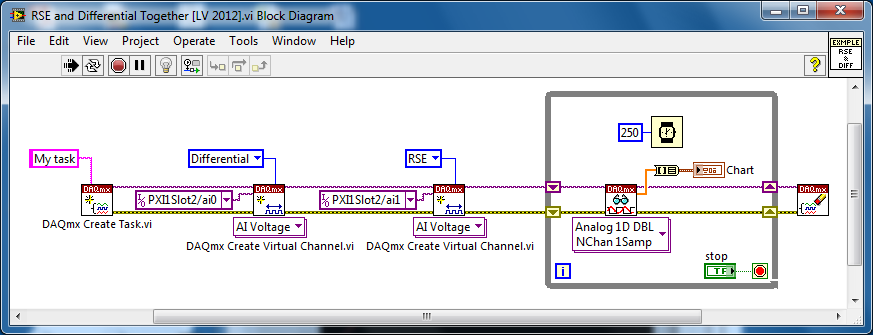
Several analog inputs with different configuration differential/CSR
Hello
Can anyone tell how to measure two analog inputs with different configurations using a USB-6009?
I am aware of the syntax for create virtual channels for the channels DAQmx create virtual so I created two strings using Dev3 / ai0:1 but I would like the first string of the CSR and the second to be differential.
So far I have found no way to specify the configuration of the separate channels.Any ideas much appreciated!
Jack
JackT wrote:
I prefer to use the 'low' level vi is therefore always curious to know if there is a way to set the configuration using the their.
It should be like this:
-
How do I get the analog input signal and send it to output analog (real time)
Hello world
I do a simple task in Visual C++ and I use PCI-6221(37 pin).
Basically, I want to send the same signal of "analog input" to the "analog output".
at the same time (or almost), to make real-time application.
Can someone provide me with sample program please.
I would be grateful if you could provide me with the great tutorial that explains
step by step everything about NOR-DAQmx for C/C++ programming.
Best regards
Khassan
This is my code in C++, you can optimize it if that seems too messy. This code reads the analog input signals and exports it through the analog outputs.
To make this code additional work of the directories include and library directories must be added to OR.
I hope it helps someone.
#include
#include
#include "NIDAQmx.h".
#include#define DAQmxErrChk (functionCall) {if (DAQmxFailed (error = (functionCall))) {goto error ;}}
int main (int argc, char * argv [])
{
Int32 error = 0;
TaskHandle taskHandleRead = 0, taskHandleWrite = 0;
Read Int32 = 0;
float64 context [1000];
char errBuffRead [2048] = {'\0'};
char errBuffWrite [2048] = {'\0'};
bool32 done = 0;
Int32 wrote;DAQmxErrChk (DAQmxCreateTask("",&taskHandleRead));
DAQmxErrChk (DAQmxCreateAIVoltageChan(taskHandleRead,"Dev1/ai0","",DAQmx_Val_Cfg_Default,-10.0,10.0,DAQmx_Val_Volts,NULL));
DAQmxErrChk (DAQmxCfgSampClkTiming(taskHandleRead,"",100.0,DAQmx_Val_Rising,DAQmx_Val_ContSamps,0));
DAQmxErrChk (DAQmxCreateTask("",&taskHandleWrite));
DAQmxErrChk (DAQmxCreateAOVoltageChan(taskHandleWrite,"Dev1/ao0","",-10.0,10.0,DAQmx_Val_Volts,NULL));
DAQmxErrChk (DAQmxCfgSampClkTiming(taskHandleWrite,"ai/SampleClock",100.0,DAQmx_Val_Rising,DAQmx_Val_ContSamps,1000));DAQmxErrChk (DAQmxStartTask (taskHandleRead));
DAQmxErrChk (DAQmxStartTask (taskHandleWrite));While (! fact &! _kbhit())
{
DAQmxErrChk (DAQmxReadAnalogF64(taskHandleRead,1,10,DAQmx_Val_GroupByScanNumber,dataRead,1000,&read,));
DAQmxErrChk (DAQmxWriteAnalogF64(taskHandleWrite,read,0,10.0,DAQmx_Val_GroupByChannel,dataRead,&written,));
}
_getch();Error:
If (DAQmxFailed (error)){
DAQmxGetExtendedErrorInfo (errBuffRead, 2048);
DAQmxGetExtendedErrorInfo (errBuffWrite, 2048);
}
If (taskHandleRead! = 0){
DAQmxStopTask (taskHandleRead);
DAQmxClearTask (taskHandleRead);
}
If (taskHandleWrite! = 0){
DAQmxStopTask (taskHandleWrite);
DAQmxClearTask (taskHandleWrite);
}
If {(DAQmxFailed (error))
printf ("error DAQmx: %s\n",errBuffRead); ")
printf ("error DAQmx: %s\n",errBuffWrite); ")
}
printf ("end of the program, press the Enter key to quit\n");
GetChar ();
return 0;
} -
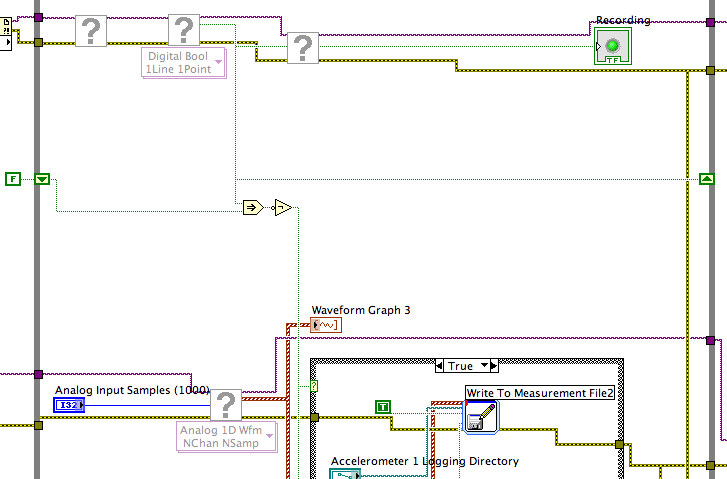
Registration of the analog inputs in continuous (Clipping)
Material:
(1) USB NI CDaq-9174 chassis
(2) NEITHER 9234 Analog Input Modules
(1) digital input module 9402 OR
Goal/Requirements:
To read the analog inputs continuous only in digital input is "high".
Problem:
Timestamp in log file prooves that logging is not continuous. It seems that the first seconds of 0.6 of every second is recording, I guess the other 0.4 is used to write custom? I can't use VI SignalExpress for this application because logging must be triggered by a high digital input.
File is attached. Thank you all!
To detect changes in the digital input, you need to compare the current value to the previous. The easiest way to do this is to plug the output of digital playback on a shift register. The Boolean function involves will tell you when a transition has taken place. See the central part of the image below. If you exchange the true and the false case of case structures, you not the inversion function. Look at the help file for more information on what the function actually implies.
You must also change the wiring of the name of input for writing custom file FIle.vi so that the name is automaticlly changed. Depending on what you want the naming system to be, that it can be simple or rather complicated.
Lynn
-
How to read the analog inputs of one Board of R for (PXI-7851R) series
You can guide me please with the steps for reading of the analog inputs of a series a. card I use as the target fpga PXI-7851R.
Have you looked at the examples provided with LabVIEW? There are examples showing how to read the analog inputs.
-
Open a synchronized session of the analog inputs and position
I want to read 8 analog inputs (only three IA in the capture of code) with a PCI-6221 card at a rate of 100 samples/s, reading 10 samples/iteration. At the same time, I want to read the position synchronized with the analog inputs. Is this possible? If I just merge the position with the analog signal I get 10 readings of position for each 100 analog input readings (see chart - Red's position). For the control of the movement, I use the pci-7342 with UMI-7764 interfaces. Could someone help me out here please?
Not necessarily. As said, speeds of up to 200 Hz should work fine with a 7342. If this is not enough, of course a 7350 could be used, but there is also a completely different approach that should work with your current hardware:
7342, you may also route the phases of encoder to the pins of the RTSI. You can use a counter on the 6221 to measure the position of your axis based on the singlas you have routed the RTSI pins. Now you can use "Measure of Position buffered" (see DAQ examples) to measure the position with the same source of synchronization than your analog signals.
I hope this helps,
Jochen
-
What is the analog input of the NI PCI-6229 impedance?
I am trying to determine the effect of a 12 K resistor that is in series with an analog input of an NI PCI-6229 data acquisition card. Resistance of 12K seems to be part of a RC filter. I have a 0-10 VDC source this supply circuit. What is the impedance of the analog input of the NI PCI-6229 data acquisition card? If it makes any difference, the analog input is connected in differential mode with a 180K resistor to Gnd AI.
Thank you
RWB
Hi, RWB,.
The input impedance is classified in the specifications 10 GOhm. So, the effect of your k 12 resistance should be relatively low. Take care!
-
Good day to all,
I use NEITHER-7350, LAbview 8.5 and try to measure the voltage from a power source.
Is there a screw that read the analog inputs. I can't open the examples.
Thank you
Have you watched the DAQmx? Create a virtual channel, start the task and read the value.
http://zone.NI.com/DevZone/CDA/tut/p/ID/5370
-
Output TTL triggers analog input with PCI-6251
Hello, I'm new to LabVIEW and have a question that I hope I can get a response on this forum. I am currently using a PCI-6251 DAQ card with a block of connection BNC-2120. I would like raise an event on an input, for example a sine wave, which is connected to AI0 analog. Then I would send a TTL pulse train via the digital output. What I'm describing can be better understood by the images of this link:
http://zone.NI.com/DevZone/CDA/tut/p/ID/3017
In the tutorial page linked above, they do mention the card PCI-6251, but when I read the specs and compared, 6251 also has analog and digital Board, trigger functions, as well as digital I / Os... so I think he should be able to do what I want it to do. Can anyone confirm this? If anyone could help me by providing a VI that could do what I ask, just to help me get started, would be greatly appreciated. Thank you!
Hello!
Please post on the Forums OR! My suggestion would be to use build it digital Pulse - Retriggerable.vi found in the Finder for example of OR. Open LabVIEW, go to help > find examples > input/output equipment > DAmx > generating digital pulses > generate digital Pulse-redeclenchables. Change the type of trigger for this departure vi > Analog edge and make the source one line APFI (pin 20 of your card is APFI0). This will generate a pulse based on an edge similar to a level that you specify.
I hope this helps!
-
Outbreak of the AO tasks with digital triggering
I'm triggering an analog using a digital triggering (PFI0) task on a NOR-6343 (USB), but don't see the behavior desired of my VI (see screenshot).
* When I shoot digital triggering (digitalTrigger = False), the AO signals appear planned (except that... they do not fire).
* When I turn on the trigger (digitalTrigger = True), however, there is no signal on the channels of the AO.
* I tried two different sources: PFI0 and the clock internal (set both rising edge). For the PFI0 channel, I connected a function with a wave generator square 5 v (the PFI0 had a slow rise... time "I think I could solve this problem by adding a small circuit of buffering). However, I expect it should work correctly using the internal clock as a trigger.
What's wrong with my code / setup?
A few follow-up questions:
* This will trigger the installation program not start indicator AO once? Or the trigger will cause the task to start whenever the finished AO signal and the trigger goes high? (I wish that it behaves like the latter)
* Just to check: the response rate of the AO task to the digital trigger should be of the order of 1 MHz?Hello kllurie,
What do you use the trigger for? The way you have the task to put in place now, it will run continuously until you press the STOP button and ignore any input trigger. If you want to be able to have the task to complete and start over with a digital triggering, you make the task two finishes and Retriggerable. You can configure the task to be finished by replacing the constant continuous samples on the Timing.vi with finished samples and giving him a number of samples to be taken before stopping. Then you can do the task Retriggerable using the property trigger DAQmx node and choosing Start > more > Retriggerable sometime before the Start.vi.
As to what it should be used as your relaxation, you'll want something with a fast rise time (so that it is detected as a numerical advantage) and is not as fast as the sample clock. If you use the sample as your trigger clock, there would be essentially no difference between your redeclenchables task and a continuous. It would end the collection of samples and then immediately redeclenchee.
Let me know if that answers your questions!
-
Test the analog inputs in a PCI-6013
Hello. I m using a PCI-6013 OR DAQmx 9.1.1 with Labview 8.2 (sued) WinXP. The jury has undergone an immersion in water during a flood but was cleaned, recognized by WinXP and NIDAQmx.
I have run the Measurement & Automation explore and use the test under option OR-6013 'Dev1' panels 'devices and Interfaces. Here, I can see that the digital and clock output work perfectly (I can change the State of the digital channels and duty cycle and frequency of the clock). The problem arises when you try to measure an analog voltage. I tried on several cases not all analog channels using NRSE and differential modes (switch accordingly connections).
The signal comes from a (4 Hz, squares and sines, 5Vpp) signal generator via a CB-68LPR connector.
I only see something comparable to the entrance of singal when you use differential inputs (signal connected by J57 and J23) AI7, but the signal I see comes with 100 mVpp instead of 5 Vpp (I can see changes in the shape, every time that I have spend of a sine, square, ramp...). I also tried connecting J23 AISENSE (J62) and AIGND (J67), to avoid the problems of floating source. The same thing happens when enter and set up the acquisition by the vicinity of data in the Explorer of Measurement & Automation. I m using the reach of the signal in the different ranges, tried with 04:55, -1 to + 1, 09:50... When you configure tasks NIDAQmx I choose to read different samples (100, 1000, 10000) rate (100 Hz, 1 kHz,...) and combinations. Anyway, the input signal is always 4 Hz. I checked the signal with an osciloscope and I see it perfectly.
Is it possible to have the broken while the digital and general-purpose analog input clock outputs are OK? Y at - it a tip for the connections I should know about? Thanks in advance for any guidance!
Thank you both, KateB and MarisolM for your answers.
I made several the tests con señales DC y con señales senoidales, instalando placa en back different computers, y no obtengo resultados positivos, is spite of what el self-test selling well. Seems that the Plaça realmente esta fallando.
I did several tests with DC signals and senoidal, installing the card in two different computers, without positive results, even if the self-test is OK. It seems that the Council really works hard.
Are concentration cotización por su reparación. Gracias!
-
PXI-6071e offset drift on the analog inputs
Hi, I have three cards PXI-6071E, sitting in a PXI-1042 chassis that is controlled by a computer with windows XP. The 6071Es are connected to the SCB-100 break out boxes that are wired to a pannel of BNC female Panel Mount on twisted pair.
I noticed that all of my analog inputs will drift around-10 V to + 10 V if they are not connected to what whether forcing them to a certain tension. This has always happened. We also see a bit of crosstalk between channels. For example if I open a panel of test in the measurement and automation Explorer I can watch the voltage read on the drift tickets through their full range, and alteration of the signals on nearby channels will appear on the channel, I am able.
Is this just standard behavior and to predict? Is there something more I could do to minimize this drift and crosstalk? I am trying to reduce noise in my system so I figure optimize my DAQ could not hurt.
Thank you
With nothing plugged into the catch to high impedance, drifting you see is quite normal. The front end of the circuitry builds up a charge, crosstalk is proabably due to the multiplexer input (did not check but I think that the 6071 has a) transferring the load to the other channels when they are analyzed.
Search the Forum of ghosting, you will find related discussions.
-AK2DM

Maybe you are looking for
-
Transfer files from windows 7 to K920
Hello world I'm trying to transfer music from my computer windows 7 to my K920, but without success. I installed ADB - driverv1.4.2 on my PC, I activate USB debogging, but K920 is still not detected. Help please? Thank you
-
NEITHER USB-6501 (24 channels, 8.5 my)
Hello I would like to know that I can use the NI USB-6501 (24 channels, 8.5 my) to do my practice? Please take look at my sheet of practice before you answer. I hope you all can help me.
-
Printer Spooler not working not
I can't print the printer spooler is not running. I can't add the new printer. LexBce file does not run. How can I fix it?
-
Does anyone know if the Sims 2 (and EPs) will work on Windows Vista 64-bit?
I was hoping to get a new computer, this weekend, but before I can, I need to make sure that everything will work actually on this subject. Microsoft says that the Sims 2 works on version 32 bit Vista, but all new computers come with the 64-bit versi
-
I decided to experiment a bit with my xp by clicking on some tweks years. now all things have gone wrong. I have a non registered avast 5 antivirus. that is now gone. -My Control Panel and all of the parameters are missing. -my c: drive is absent, th