The channel numbers and the USB-6259 BNC
The front panel USB-6259 BNC labels BNC connectors as channels 0-7 and 16-23. Most odd... I have a software written in C++ using NOR-DAQmx that my client will try to use with this unit. When using the channel superior numbers he (not unusually, really) Gets the error-200077 saying that they can only be used in unbalanced mode. But it is not natural for him to use the channel numbers printed on the front of the unit.
Can someone tell me how the front panel of this device is the channel numbers, you must specify in the code?
This requires the switch (source of the source/grounded) floating FS/GS that appears under each BNC connector?
Here's my proposal: differential mode: in the software, channels 0-7 are front channels 0-7. Software 8-15 channels are front 16-23.
Asymmetric mode: software channels 0-7 are cover 0-7 and 16-23 software channels front 16-23. And 8-15 and 24-31 channels are absent...
It takes just the opposote of what you have. In differential mode, aix is paired with aix + 8. so, ai31, ai9, AL10, ai11, ai12, ai13, ai14, ai15, ai24, ai25, ai26, 27, ai28, ai29.ai30 and ai8 channels are not available for selection in differential mode. Front panel for ai15-23 labels should be correct and matches what you select in the software.
Tags: NI Hardware
Similar Questions
-
I want to integrate the ANSI C sample program ReadDigPort - ExtClk.c in my own big package.
I want to use the internal clock of the BNC NI USB-6259 (.. 80 kHz 120 kHz).
In the document:
High speed M: Series Multifunction DAQ for USB - 16-bit, up to 1.25 MECH built-in BNC connectivity. / s,.
is written:
Or sample DI source clock: Any PFI, RTSI, HAVE sample or convert clock, AO, Ctr n out internal and many other signals sample clock
The digital subsystem doesn't have its own dedicated internal synchronization engine. Therefore, a sample clock must be provided another subsystem on the device or from an external source.How can I use internal clock case OR USB - 6259 BNC for the acquisition of digital data in my own big software?
With what other subsystem on the device can generate a source of the clock? How?It is possible to set a clock on an internal counter (for example ' Dev1/ctr0"):
Creates channels to generate digital impulses that define the freq and dutyCycle and adds the channel of the task that you specify with taskHandle.
DAQmxCreateCOPulseChanFreq (taskHandle, "Dev1/ctr0" units, clockName, idleState,
initialDelay, freq, the duty cycle); worksBut it is not possible to drive this internal clock to a terminal (for example "/ PFI0/Dev1"):
DAQmxErrChk (DAQmxCreateCOPulseChanFreq (taskHandle, "/ PFI0/Dev1", clockName, units, idleState, '))
initialDelay, freq, the duty cycle); does not work: error DAQmx: measurements: type I/O of the physical channel does not match the type of I/O required for the virtual channel you create. Name of the physical channel: PFI0. Name of the virtual channel: clockThe sample clock source can be derived from an external terminal (for example "/ PFI0/Dev1"):
Sets the source of the sample clock, the sample clock rate and the number of samples to acquire or generate.
DAQmxCfgSampClkTiming (taskHandle, "/ PFI0/Dev1", maximumExpectedSamplingRate, DAQmx_Val_Rising, ")
DAQmx_Val_ContSamps, bufferSize); works. Acquire or generate samples until you stop the taskBut it is not possible to derive the internal counter of the clock (for example ' Dev1/ctr0"):
DAQmxCfgSampClkTiming (taskHandle, "Dev1/ctr0", maximumExpectedSamplingRate, DAQmx_Val_Rising,
DAQmx_Val_ContSamps, bufferSize); does not work. Error: Acquire or generate samples until you stop the task: make sure that the name of the terminal is valid for the specified device. See Measurement & Automation explore valid names of terminals. Property: Property of DAQmx_SampClk_Src: DAQmx_SampClk_ActiveEdgeSource device: Terminal Source Dev1: Dev1/ctr0Hi datafriend,
using what it says is correct:
Or sample DI source clock: Any PFI, RTSI, HAVE sample or convert clock, AO, Ctr n out internal and many other signals sample clock
The digital subsystem doesn't have its own dedicated internal synchronization engine. Therefore, a sample clock must be provided another subsystem on the device or from an external source.This means that if you do not use an external signal as clock you can use the sample clock to HAVE it on board or at the output of the internal counter.
There are also 2 ANSI C examples in this regard:
http://zone.NI.com/DevZone/CDA/EPD/p/ID/4485
http://zone.NI.com/DevZone/CDA/EPD/p/ID/4488
So in both cases you have to use a fictitious task you need only for the generation of the internal clock (HAVE or CTR)
-
NI USB - 6259 BNC DAQ: analog input signal cross on the question
Hello
I use the NI USB-6259 BNC DAQ unit to acquire a four-channel analog signal, and I'm having a problem with a signal that affect others. The circuit, I am running is:
I have a wire connected to a battery (two AA batteries at ~1.5V), which then feeds the signal cable to a BNC cable, which feeds an analog BNC of data acquisition channel. The field of NBC feeds to another wire, which is attached to a conductive plate. The idea is this: when I touch the wire connected to the battery for the metal plate, I complete the circuit and thus get a binary not anything at all about 3V. When I tested with an osciloscope using two channels (each earth connection to the metal plate) I get independent steps whenever I touch any of the sons of the respective batteries to the metal plate (i.e. it works as expected). However, when I use it with data acquisition, whenever I touch a wire, I get a response in all other channels (3 others), even if their respective sons does not touch the metal plate.
No one knows why this happens, and how I might be able to stop this 'cross-talk '?
Thank you
Veritas
I see, and you're right. This request will have trouble with crosstalk. Luckily the ground channel thing should help you.
Configure your DAQ to collect twice as many channels as you need. Connect your wires in the odd channels and short circuit (ground) the entries of those even.
Now when you scan the channels it will always technically crosstalk, but it will come from a channel to the ground so that there will be nothing to interfere with your measurements.
At least that's the theory.

-
Using ChangeDetectionEvent with the NI USB-6259 housing
Hello
I am very new to labview and LabWindows, so maybe it's very trivial to solve.
I would like to perform an action (change some elements of the user interface) whenever I get a rising edge of a TTL signal.
I hoped to achieve by following the example of ReadDigChan-ChangeDetectionEvent, and by defining a DAQmxRegisterSignalEvent() front on one of the digital input lines, but I can't even use the example for my
USB-6259 (BNC).
When I try to perform detection of changes on the lines from the port 1 and 2 I get
Modalities indicated do not support change detection. Select the lines that support the detection of changes. Device: Dev1 physical Channel: port1/$line0 the task name: _unnamedTask<0> Code of State :-201020
I missunderstand something? Should the digital in ports on the detection of change of 6259 support?
When you try the same thing with port0 the application hangs for a long time and threw just a message saying that
DAQmxReadDigitalLines() timedout.
I hope this is enough information to answer the question. If not, what else do you need?
Thank you
Manual
Hello
It seems that the USB-6259 does not support the detection of changes.
Link:
In NOR-DAQmx digital change detection
-
Synchronous channel multiple acquisition USB-6259 (phase measure)
Hello!
I want to create a user-signal (1 k at 20 kHz) in SignalExpress, generate it with the case NOR USB - 6259 BNC and measure with the same device after that the signal has passed a DUT I need the answer for a fixed term.
For the moment, I'm trying this: I connected the output via a Y-coax analog (length 1 meter) to TWO analog inputs.
Because the input channels have been grouped with the add a channel button, the data acquisition should occur almost synchronous.
However, sometimes the phase response is zero (cause as expected the two signals must be equal), but sometimes it "jumps" (especially when I am running the new project) and increases or decreases linearly on the frequency (so there is a time difference between two measured signals).
I don't think that running is the problem here, because referring to the manual, it's about some µseconds and I have not yet change the range of voltage between input channels. Furthermore, the magnitude response is fine.
I has not yet perform to synchronize the input channels with the output of the channels either, but first I would be recognizing a solution for the entry-entry-synchronization, (I don't mind if it is implemented in LabView).
Thanks in anticipation, Daniel
Hello Daniel,.
the M-Systems Series DAQ using a switch to sample multiple channels. So you have to take the time to switch into account when
you do measures such as phase shift of two signals.
I took your project Express of Signal but also created a LabVIEW VI to double check, and you can see exactly the same lag between the two
sampled signals. If you want to measure the true phase differences, you have to use a device of simultaneous sampling like S or DSA series devices (there are more a few others).
concerning
MArco Brauner NIG.
-
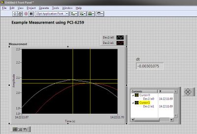
Bad drift with USB-6259 devices and acquisition of data PCI-6259
We have both a USB-6259 and PCI-6259 installed on a single computer, linked to a SBC-68, with Matlab and Toolbox of data Acquisiution.
For the purposes of test base, I wrote a script that generates a sinusoidal signal output based MATLAB, for a single DAC output. I wired this single DAC output to two channels of ADC of entry. For each sample output DAC, the script also takes a sample entry of ADC on each channel.
--> Ideally, if everything works correctly, after you run the script, I see two channels of input ADC vector. Tracing of each channel should give me a nice sine wave in Matlab.
--> When I made trace data, here's what I get (see attachment).
-->, I looked at the DAC output with an oscilloscope, and the DC offset is very close to 0 (this indicates to me that the part of output DAC works very well).
Why is there this negative DC drift on two entries?
Forgive my lack of knowledge - I know the difference between the DIFF and CSR connections, but I don't know where is the 'setting' for DIFF/CSR (what is a button/switch on the USB-6259 case? Is it a software control in the code?)
-
Communication problem between LabView and acquisition of data USB 6259
I want to monitor a data USB-6259 acquisition using LabVIEW 8.6. However, when you try to create an explicit task (using the DAQ assistant) in order to acquire a signal, I get the message asked supported device found¨. I can see the USB-6259 under ¨Devices and interfaces¨ to the MAX, but when I try to import the configuration data for NOR-DAQmx 8.7.2 in MAX, I get the message ¨Can´t import file configData.nce. File not found¨. I use NEITHER-DAQmx 8.7.2. Any suggestions?
Corneliu
Hi, Corneliu,
This question could be generated due to a corruption of database of MAX. Here is a link to restore the database to the MAX.
http://digital.NI.com/public.nsf/allkb/2C7480E856987FFF862573AE005AB0D9?OpenDocument
Just follow the steps and let me know if that solves the problem.
A greeting.
Jesus.
-
Types of stitching and massive cable USB-6259
While I wait for my USB-6259 with massive endings happen I would like to start working on some PCB for my custom connections and that leaves me with a few questions unanswered.
I'm looking for concrete answers, because the site and the pictures are not very clear.
-Are the cables SH68-68-EPM male to female?
-I see in the descriptions as the unshielded break tips CB-68LPR and CB-68LP have male connectors.
But the armoured breakout boxes (SCB-68) do not tell or show what they have. I guess they have male connectors as well. It is also why I guess the SH68-68-EPM cable is male-female.
-I can't tell if the unshielded cable R6868 is female-female or gender? The picture shows 1 female end, but not the other.
-Finally, the documents for the USB-6259 show the pinout for the version terminal screws, but not for the terminals of MASS.
I need to know what are the signals on each pin of the scsi cables to put 68 pins on my custom PCB connectors.
Thanks for any help
In the USB-6259 Product Page, go to the "resources" tab. Under the tab "resources" are the designs listed for the device.
-
How to connect USB 6259 so that I can generate trains of pulses of a meter
Hello
We just bought NI USB-6259 BNC. We used to use BNC-2110, which integrates the connectors BNC for trigger and the meter so that we can send trains of pulses through it to our electric Stimulator.
However, I find no terminal BNC for the output of the meter on the new device. Could someone teach me how do?
Thank you
Jay
Hi, Jay.
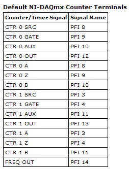
Big question. The screenshot below will give you the Signal of Counter/Timer associated with its respective PFI line:
This table is located in the NOR-DAQmx help (using terminals of NOR-DAQmx devices"OR USB - 6259 BNC).
To access these lines PFI one of the BNC (User 1 and User 2) user-defined, the line due to PFI line of the user desired. For example, if I wanted to access counter 0 Out of 1 BNC user, I would wire pin 1 USER on pin 12 of PFI. Manual specifications USB-6259 BNC does not give a good description of how to access the user 1 and user 2 BNC, so I refer to page 9 of the Manual of the BNC-2110. It's the same idea, just different pinout.
Let me know if you need more information. I hope that you are having an amazing day!
-
Can't see the rise on a USB 6212 BNC channel time
Hello
I use an acquisition of data NI USB 6212 BNC to monitor the rise time. A single channel (AO0) is used to define a voltage all followed another channel (AI1). The problem I have is that I'm not able to see the rise on AI1 time, only a jump to the specified voltage.
I started to edit one of the material examples. Initially, I have connected the two channels via a BNC connector to BNC cable but thought I better with a simple circuit. I set up a resistance on a model and connected my channels accordingly with crocodile clips. Unfortunately, the result remained the same and all I see is a jump to the previous setting in tension (usually 0) to the new I entered with a infinite slope (vertical line).
I am fairly new to DAQ and plan to work with it for a while. The simple circuit will be expanded considerably in filter tests and other applications, but for now, I have to get the basics. I would appreciate help, that you can offer; only currently, my thoughts are if this could be a sampling problem (I put it to 400000 above) and if I may add a ceiling to slow things down. I want to get this to work, however, so I could develop by looking at rates of filters and sweep of the go-around.
I enclose my screws in the hope that they will help you decipher the problem. Have tried different combinations on DAQ Read and Write with single or multiple and 1DB/Waveform channel, although I'm pretty green in their functioning, without success.
In hoping to hear talk about you,
Yusif NurizadeYusif Nurizade,
What type of signal you generate on the AO line? The default value in the output array is a single element zero. That didn't exactly have a rise time!
To measure rise times sampling on the line frequency should be fast enough to get samples of several over the course of the rising part of the measured waveform.
The signal on the AO line will always be in the steps from one value to another. This is the way of working with D/A converters. 6212 specifications indicate a speed of 5 V / us. If two successive samples were 0 to 10 v it would take exit 4 move us from one value to another. Same samplng HAVE it line 400 kech. / s, you would get no more than an intermediate value and would not be able to measure the rise time.
Try putting an R - C circuit with a time constant on the order of milliseconds between connections AO and AI. You should be able to measure it.
Lynn
-
Temperature measurement and the CJC using thermocouples on a USB - 6229 BNC
Hello
I'm trying to get the measurements of temperature using type K thermocouples on the box nor usb-6229 BNC. SignalExpress software doesn't let me choose 'Built In' to the Source of the CJC. So, I must select 'Constant', which means that I then have to follow the evolution of the temperature during the day with a separate meter and adjust the value of CJC accordingly to maintain an accurate reading. Is there a way around that to avoid having to monitor the room temperature at the junction?
Thanks in advance
Mike
Hi Mike,.
It seems that you have managed to find a solution for you have this problem, which is great news.
However, for future use, if you had bought the 6229 with massive ending (rather than the interface BNC) then you might have interfaced unit with a block of connection SCB-68 (see link)
http://sine.NI.com/NIPs/CDs/view/p/lang/en/NID/1180
The SCB-68 has a CYC source built-in, so you might have used in conjunction with 6229 (mass layoffs).
A bit of in the way, but I thought you may be interested.
Best wishes to you all
-
We are looking to buy a card PCI-6259 usable on a Linux machine. We would use NIDAQmx to access the card. If we were to use only a few channels to increase the sampling rate, do I need to select specific channels?
For example, the card is 1 MHz. If I select the channel 1 and channel 2, I can taste each channel at 500 KHz. could I choose 8 channel and channel 13 and still be able to sample each channel to 500KHz? Or need of specific channels to use when a subset of channels are selected?
Thank you
-Tom
Thanks for the quick response.
-Tom
-
generate a digital triggering out CH1 (low and high) for the USB-5133
Hello
I would like to generate a digital triggering on the USB 5133 CH1, is this possible? I tried with the PFI 1 successfully but the output is only 3.5 v and I need to 5V, because this trigger signal goes to a box of pulse generates a signal, which is received by the CH0 on the USB-5133. This configuration works on the 5102 OR but because of the treatment, I am obliged to try a new device.
Channel 0 and 1 are only entries then you will not be able to use them to generate a signal. All of our products current digitizer that are recommended for new designs use 3.3V CMOS logic levels for PFI lines in output mode. Your best bet to generate a digital triggering 5V would be to use an external buffer that can accept 3.3V CMOS levels as an input, but is under voltage of 5V. Here are some that might work for you, but there are many others: http://www.onsemi.com/PowerSolutions/product.do?id=M74VHC1GT126DT1G adding a buffer in line with the trigger signal will add delay, so you will need to ensure that it is acceptable for your application.
Hope this helps,
-Matt
-
The streaming of multiple channels directly to CSV USB-6210?
I would like to stream up to 16 channels of data to a CSV file. My sample rate can vary from a file in a file, but I can reach 1 kHz. I understand the disadvantage of using text rather than PDM or binary files, but I have to be able to read these files later with programs such as Excel (Excel 2007 can make 1 million points).
I have no trouble writing to TDMS files as seems very straighforward. I wonder though, it would be more efficient to use the TDMS files as the data are acquired and then after I stop, read the PDM and convert to CSV or just directly save to CSV? I only say this because I don't know if Labview can broadcast on a text or CSV file at 1 kHz.
The scenario. The user will begin acquisition (using the USB-6210) to start playback 16 channels, applying multipliers for some data, and then send to a drive. Don't worry about the file size, the operator will be told that if it samples fast it must limit its total sample time. He has the ability to run slower to achieve longer sampling frequencies.
Bottom line is I want good data for all 16 channels timestamped. No header information, nothing other than data raw beginning to end.I've seen several posts where the notice has been using TDMS files. Yet once again, I am not opposed to that, but I need to end up with text files.
Jeff
LabVIEW can handle this, if you do it right.
1. If you are not already, use the design data of producer/consumer model. It should be a template provided with LabVIEW. This will allow you to take continuous data because your data treatment/backup of the routines take place in a separate thread. If the hard data recording longer than reading the data, LabVIEW will keep only the size of the queue more and more with new data and I hope that you will not run out of memory system.
2 write. you data in "chunks". If you expect to write each data point to the disk as soon as it is available so that will probably be very tax on performance due to the excessive amount of 'read/write' header to your disk controller information and other things. It is better to save 1000 samples at once, for example. This way you are 'hit"your disc 10 times per second instead of 1000 times per second.
3 ASCII files are very large, but I too tend to use them due to their convienance. If you think about it, a 32-bit value can be "12332.0123" which in the ascii code is rather 80-bit (1 byte per character, 8 bits per byte, 10 characters is 80 bits or more than twice the amount if stored as a number 32-bit floating point). It is therefore logical that if you have problems with performance (even after the application of 1 and 2) you write to a binary file. Then, you can easily write a program that reads the binary file and writes a text file.
4. If your computer has enough memory, you could put everything in memory and save it in a file at the end of the data collection. You will need to add more controls and other things if you were writing this LabVIEW application for someone else.
-
Installation of the enclosure OR USB - 6259 Visual C++ Runtime Library Runtime Error
Hello
I am trying to install the NI USB-6259 DAQ card but I get a runtime error that says
Microsoft Visual C++ Runtime Library
Runtime error!
Program E:\setup.exe
This application has requested the execution to terminate in an unusual way.
For more information, contact the application support team.
I also installed LabView 7.1 but I still keep getting the same message. Any help please?
Thank you
Re-installation of Windows has not solved the problem.
The resolve this problem change the regional and Language Options of the control panel settings to the United Kingdom. That solved my problem.
Thank you
Steve
Maybe you are looking for
-
iMac 27 freezing at random, leaving weird video on screen
I'm having a problem with my Imac end 2013. For the last week or two, he has been randomly freezing upwards. The display freezes just upward to let appear an odd of the fragments of the screen. All I can do is hold down the power button and shut down
-
Hi I have the impression that my iPhone 6s is seen virus... Is this possible? As I mail, if there is an attachment, ters a few small file with it. Then you can help! Moreover, my camera does not sometimes...
-
How can I remove a virus from the battery!
Hi all Today, I opened google chrome to see if the hunger games the last of them has been able to watch in cuevana 2, but a window with a warning appears saying that if I close a virus will affect my battery. I didn t have a choice, then I close it,
-
Hi all We just bought a PowerConnect 3548P. I configured an IP address, user name and password on this subject by the console then configured using the web console. I unplugged the power subsequently. I found all the configurations (settings after th
-
I have a property webview and URLs defined in QML as follows: WebView {}ID: mWebViewobjectName: "mWebView."URL: "http://www.google.com".} Then I try to load a different URL in C++ as follows: mImageView = root->findChild ("mImageView"); mWebView-> se