The engine fault analysis
Hi all
I use a CRIO-9075 with a NI9205 and Ni9263 to control the movement of a hydraulic jack. Activation and position/force signals are analog. I use the library softmotion to create an axis and take advantage of the generator of the trajectory and the control loop to execute in the FPGA.
I'm running the CRIO using FPGA and like softmotion for independent axis I synchronize RT and FPGA, for which I've read the engine periodically at 100 Hz.
The problem is that the analytical engine gets in a few seconds in fault mode. To return to the active mode, the only way is to reset electrically the CRIO.
I have attached an image of a minimal example in which to read the scan engine mode and read two panel controls before FPGA. The analytical engine returns 3 (default mode), but the variables read from the front panel are correct.
Have the engine of analysis in fault mode I cannot synchronize the RT and FPGA as in the example softmotion.
Why is my engine entering mode fault with the wrong 66341?
Thanks in advance
This is a bug described in the following link with a workaround that works
http://digital.NI.com/public.nsf/allkb/E2F4F2E4F3A91F6E86257BB9006589D1
Tags: NI Hardware
Similar Questions
-
One click search options displays will not be so, how do I change the engine?
I've been in the Tools option to check I have other several other search engines checked, as amazon ebay twitter etc. but no menu drop-down will appear in search engines click bar when I click on it... only the option edit my preferences. I checked all the engines appear in the tools, then options, and then search for window and restarted firefox but still nothing when I click on the search bar.
How can I fix this please?Hi Jo.L, looking for different options will show up once you start typing in the search bar...
-
I don't see the link to the engineering of Netgear XWNB5201 units for my Mac?
I don't see the link to the engineering of Netgear XWNB5201 units for my Mac?
I thought that this establishment should be simple, plug-and-play as such.
The security on the access point button is not very good. I think that this will be returned for a refund
Netgear equipment is now packed ready to mail to perceive as I spent quite long try to put equipment which is completely lost time.
I am disappointed with the Netgear site for support when you follow the instructions in the manual and connect, I see is complaints and comments and no solutions. The site is in my opinion, very poorly built and managed.
As solution I just ordered Devolo units that have been strongly recommended and will be with me in a few hours, and my Netgear headache will be resolved.
-
How can I get the engine move TETRIX VI is back?
I bought LabVIEW Education Edition 2009 earlier to use with TETRIX for my class. I have since installed LabVIEW 2011, 2013, 2014, and 2015 for FRC teams that I coached. Recently, I tried to reprogram my TETRIX (using NXT) kit, but the VI, I need to order the engines is missing (see screenshot). When I try to install only the Module of NXT from the 2009 original installation DVD, I get the following error:
OR LabVIEW 2009 LEGO® MINDSTORMS® NXT Module
Could not install
LEGO MINDSTORMS NXT x 64 Driver (already installed higher version)
OR LabVIEW 2009 LEGO MINDSTORMS NXT Module (already installed higher version)I hesitate to uninstall all other versions of LabVIEW because of the code of the team. Any suggestions for how I can control my TETRIX components again? See you soon.
Hi izetetic,
I don't know why screw has disappeared from your NXT Module. You can uninstall only the NXT Module and then reinstall?
If this does not work, you can use a more recent version of the Module NXT, now called the MINDSTORMS Module, for a more recent version of LabVIEW: http://www.ni.com/download/labview-nxt-module-2015/5418/en/ . Since you have already installed LabVIEW, this comes for free.
In versions 2010 and beyond, you must configure the TETRIX engines using the schema editor and then use the IO > engine pallet to program the engines.
-
Powder dosing machine? Direct control of the engines?
Hello world
I hope it was not shown below, but I start my worki with nxt and labviev and a certain problem.
I want to build a dosing of powder, which consists of two conductors of powder (driven by motors) and the weight of lab controlled by RS232.
The goal is to be able to make precise mixtures in order to weigh the empty box of weight, tare, and then adds a charger of the weight of the powder (A) checks how much gave - if not enough adds some etc... etc... continued with 2 powder and mix to...
The problem is that I know that I can write the labview NXT program to run the NXT brick, but it would be very complicated to use - the best way would be to take direct control over the engine via NXT - therefore when I want the engine to move a few degrees it should not start the program in the nxt brick do the program level LAbview... IS this possible? Can I use brick NXT as a controller of engine itself?
Thank you
Marek
Marek,
This is possible in 2009 in Module NXT and NXT earlier toolkits. In 2009, just write your code NXT in a VI that is not the target of the NXT (e.g. it is targeted at the Instance of the Application My Computer/hand). The VI NXT know when they are targeted on the computer and automatically send direct orders to the NXT brick via USB or Bluetooth.
In previous versions of the tool NXT, you must use the Direct screw of NXT to accomplish the same task, which is not as transparent as the new method, but all works the same. Please let us know if you have any questions about how to apply this.
See you soon,.
-
A USB from a PXI power control, turn the engine in real time
Hello
I need a USB of my target in time power control real (PXI) who installed the engine time real Labview (no windows installation).
If I'm not mistaken, this is not possible with the USB port on the controller (NI PXI-8108) that I have not installed windows to recognize the device. As far as I could see, it looks like I need to buy a special card for PXI that allows me to interact with USB devices.
Is there someone who came across such an environment to see if it's the right approach?
Thank you very much
Dani
For those who are interested, in order to control the USB equipment, the following requirements is necessary for a Phar Lap ETS RT OS operating system:
In time real LabVIEW 2011 or higher
VISA, 5.1 or higherhttp://digital.NI.com/public.nsf/allkb/5F30CD20D4D986CC862576CF00748B15
http://digital.NI.com/public.nsf/allkb/ED3790E56FE969F8862575C30076063C?OpenDocument
The upgrade of the system and the second link will allow such equipment.
-
How to change (not completely override) a sequence of the engine callback
I understand the general idea behind changing engine callbacks, but how do I know what the original engine callback? In other words, how can I see the steps for TestStand engine by default reminders? Specifically, I work with the SequenceFilePostStepRunTimeError engine callback. I want to add a feature that runs when a specific error code is displayed, but the engine ran normally callback (that is, to have the window "what do you do?" pop up) for all other errors. I'm confused because when I first 'Add' recall of SequenceFilePostStepRunTimeError to my file of the client's sequence, the reminder is empty. Does this mean that my specific error handling code is the only thing that is going to run? Or if you're running in addition to the default SequenceFilePostStepRunTimeError code? How to see the code behind SequenceFilePostStepRunTimeError?
I appreciate the help!
-Bennett
See this example:
\Examples\Callbacks\PostStepRuntimeErrorCallback\ErrorHandlerExample.SEQ In it, you will see the comment:
"If this flag is set, TestStand does not send a UIMsg_BreakOnRunTimeError event to the GUI. This step sets the flag to prevent the GUI to display a runtime error dialog box because this recall has already introduced a runtime error dialog box to the user. »
where is the following:
RunState.Caller.RunState.ErrorReported = true
It's what turns off error processing normal teststand. There is no default reminder that you override, there is a built-in default behavior.
Hope this helps,
-Doug
-
Error-201314 whenever the engine killed
Hi guys,.
I'll build a test bed that takes a few smaller engine size measures. I use the 9188 cDAQ platform and a module in the series C 9401 to get the signal of an encoder that is mounted on the engine. Whenever I kill the engine I get code error-201314 saying the following:
DAQmx error: sampling Multiple clock pulses have been detected within a period of the
input signal. Use a sample clock rate that is slower than the input signal. If
you use an external sample clock, make sure this clock signal is within the j
Itter and voltage level specifications and seedless.The way I have the configuration of the task, it's pulse tachometer to act as an external sample clock and charges against the edges of 20 MHz clock, so I can hardly believe I'm getting any type of engine accelerates faster than the clock of 20 MHz. Anyone has an idea what this message means? So, I wonder if I need to be more careful about the way my reasons are connected.
Thanks for the help,
Ryan
Hi Ryan,
Small defects on the edge rising or falling of your tachometer signal could be picked up as additional edges. I suspect that the Act of powering the motor is presenting the noise on the line, whose meter is picking up as the edges in double during transitions.
The 9188 she supported for digital filtering on the meter inputs - introduced feature in DAQmx 9.4 for the 9188. You can use the digital filtering to reject any pulses below a certain duration. From your description, it seems this would be a likely solution to the problem.
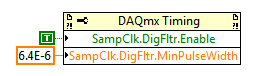
In LabVIEW, you can define a digital filtering of the sample with a property node DAQmx Timing clock signal:
If you use a different API and ill have to find the equivalent property do not forget to let me know. Remember that if you use a version of DAQmx before 9.4 you will need to update your driver to have the feature available for your 9188.
Best regards
-
Stop the engine when detects digital impulses of the reflective light sensor
Hello
I am doing my school project and I managed to make the deepening of the engine via digital port of the USB-6008 by setting the Boolean value of output in a while loop with use cases, but now I faced a problem because I have to use it with a reflective sensor and stop the engine when he feels a digital pulse. The sensor is configured as a counter using PFI0 on the USB-6008 with a circuit that will send in a digital pulse for data acquisition.
How to stop the engine when the detector reflecting is blocked, and then start the deepening again when it is not blocked
Thank you
The top spot is always implemented as a counter. You must change the DAQmx create channel as a digital input and the DAQmx interpreted as a Boolean variable digital 1 channel 1 sample.
-
How to implement Canopen on FPGA to run the engine using NOR-9881?
Dear,
Your support will be highly appreciated,
There is only one available for NOR-9881 example.
Please note that the following materials were properly connected:
cRIO-9024, cRIO-9113, OR-9881 and motor Nanotec (SMCI36 against L2818L0604-T5X5), the following
sites Web shows the engine Nanotec in details:
http://us.Nanotec.com/products/660-L28-linear-actuators-with-trapezoid-spindle/
http://us.Nanotec.com/products/1041-SMCI36-stepper-motor-and-BLDC-motor-position ing-control /
The main problem is how to configure the inputs and outputs, where, in most examples, the entry and exit have been automatically
configured.
the following three examples and I wonder how to start:1 - example Nanotec: dependent VISA controls for data transfer
http://us.Nanotec.com/support/application-notes/LabVIEW-example/
2 - reference example CANopen for series C OR - 9853 Module CAN:
the NOR-9853 has default Can0 which was used in the codehttp://zone.NI.com/DevZone/CDA/EPD/p/ID/6093
3 - from finder labView example: search for 9881 then choose
NOR - CANopen_cRIO.lvproj, which depended on SDO orders for transfer orders
The attached picture shows that NEITHER-9881 can be seen, after compilation and
loading the bitfile FPGA.
Please, please advice me:
1. how to start?
2. how to create variables of entry for NI9881?
3. how to implement CANopen mode FPGA? where there is no CANopen palette.Thanks in advance and
Hello!
From my understanding, the 9881 can be treated from the FPGA, but only from the application of the RT. I think that the point 3 of your post examples of the use of the module fine.
Kind regards
Georg
-
reverse the direction of the engine
Hi, I need help with the following:
Detection time and the weft: sensor of the LDR (photocell) should be able to detect whether it is day and night (light or dark). During the day, if the Sun is so bright, special curtains should automatically shadow through the engine temperature sensors. During the night, curtains must be retrieved automatically. Note that the user has the ability to override decisions could make about deployment or recovering curtains.
I did a job on the vi program. However I don't know how to reverse the direction of the engine through labview. I'm controlling the speed of the motor using function (1 sample of Charron 1) freq counter DAQmx writing a command button. So I can't specify a negative cycle. Any suggestions?
My labview code is attached.
Thanks for the reply. I solved the problem by using a component electric H bridge and related lines Mydaq DO0 DO1
-
The good examples of the construction and analysis of the data in bytes?
Hi all
Very soon, I'll have to find a way to build messages to bytes to send to a serial port and a serial port to receive and review to the basis of events out of...
However, before I delve into the complexities of the serial port communication and VISA, etc... I would just like to see some examples of working mainly with data of bytes.
I found how to get a digital constant the byte value... the binary representations signed and unsigned, etc..
However, if I could find a simple example or tutorial just to see how to assemble the byte-code... and how to analyze it, it would prove invaluable for me to study. I've never really worked at the byte level / binary front... and a few examples with LV would be very practical.
Anyone know of any good links out there something like this?
I'll eventually be sending 5 bytes out I need to build... and will receive 9 bytes in, each of which I need to parse out and respond...
Links or information GREATLY appreciated. I'm pretty decent analysis of the chains, real expressions, etc... but never worked with the construction and analysis of the data in bytes.
Thank you in advance,
Cayenne
If you are comfortable with binary data, you can use the Boolean charts. Look at the number of table Boolean and array Boolean functions numbers. Instead of masking with an AND, you can easy to use array index to check a bit particular.
-
Hello! ...
I have developed a program that has the algorith as follows:
1 x steps and Y steps determne table of pixel size I want.
2. for each Y increment the X scan by a fixed number of steps, then there
3 step 2 is repeated until there is reached its MAX State.
Problem:
After the scan X say 10 steps I want to reverse and go back to the original, and then again after Y increments X scan and return to original.
Its a RASTER scan basically.
I'm not able to understand why and how to add a part to get the engine back to its original position.
Please find the VI and tell me my mistakes.
Thank you
Hello
You have two nested while loops: one that moves in the direction y and one inside that moves in the x direction. There are two ways you can implement replacing the x-axis zero.
1. the stop direction x loop condition is once he traveled to the stop. You can add that a deal right behind what just loop said the engine back to zero.
2. in management's loop before the axis x running tell the x axis to return to zero. This would lead to zero each time before axis x begins his move.
Both ways will accomplish the same thing but got it back after the move and two the fact before.
Kind regards
Greg H.
-
The engine through series control
Hello
I'm working on a project that requires the operator to control the engine rpm and it is on and off a labview interface. The engine is a Kollmorgen servomotor(AKM42E-ANDNC-00) that is connected to a controller of S20360-VTS of danaher. The controller is connects to the computer via the serial port.
My question is if there is a way to control this motor through the connection in series of the computer. I tried to communicate with is the use of channels but received only gibberish back. (I do really not understand communication channel). The settings for the serial communication are correct (with the exception of flow control that I'm not sure). Any help would be appreciated. You will find info series beginning on page 57 of the manual of the controller.
Thank you
So, after having spent some time yesterday and today with Kollmorgen technology support. I determined that t he car engine and cable series are actually owners and there is no way to interface with the engine outside of applications of Kollmorgen. We tried to run commands and an engine test in Hyperterminal and Labview and the engine ended by locking for safety. Thanks for everyone entered btw, I learned a lot.
-
Operation not supported. Cannot open a document processed by the engine of JRC in the C++ stack.
I have visual studio 2010 with Crystal reports extension add on. Everything works perfectly in development (Win XP Sp3). When I create my Web site and try to access a report crystal on my web server (Windows 2003 R2 32 bit) I get the following error:
Unsupported operation. Cannot open a document processed by the engine of JRC in the C++ stack. Description: An unhandled exception occurred during the execution of the current web request. Please review the stack trace for more information about the error and its origin in the code.
Exception details: System.Runtime.InteropServices.COMException: Operation not supported. Cannot open a document processed by the engine of JRC in the C++ stack.
Source error:
An unhandled exception is generated during the execution of the current web request. Information regarding the origin and location of the exception can be identified using the exception below stack trace. Stack trace:
[COMException (0 x 80041811): no support of operation.] A document processed by the engine of JRC cannot open C++ stack.] CrystalDecisions.ReportAppServer.ClientDoc.ReportClientDocumentClass.Open (object & DocumentPath, Int32 Options) + 0 CrystalDecisions.ReportAppServer.ReportClientDocumentWrapper.Open (object & DocumentPath, Int32 Options) CrystalDecisions.ReportAppServer.ReportClientDocumentWrapper.EnsureDocumentIsOpened (+ 95 + 270) [CrystalReportsException: load failed report.] CrystalDecisions.ReportAppServer.ReportClientDocumentWrapper.EnsureDocumentIsOpened () + 333 CrystalDecisions.ReportAppServer.ReportClientDocumentWrapper.get_ProductLocaleID () + 31 CrystalDecisions.ReportSource.CachedObjectReportSource.GetReport (context RequestContext, Boolean bAddToCacheWhenCreated) + CrystalDecisions.Web.CrystalReportSource.get_ReportDocument () + 201 Reports_POD 438. Page_Load (ByVal sender As Object, ByVal e As EventArgs) + 55 System.Web.UI.Control.OnLoad (EventArgs e) + 91 System.Web.UI.Control.LoadRecursive () + 74 System.Web.UI.Page.ProcessRequestMain (Boolean includeStagesBeforeAsyncPoint, Boolean includeStagesAfterAsyncPoint) + 2207 I installed CR2008, 2011, etc. nothing works.
I've looked everywhere for a solution to this error.
If anyone has a solution please post. It would be much appreciated!Thank you
WS
Salvation Will Stoner,
Your question of Windows Server is more complex than what is generally answered in the Microsoft Answers forums. It is better suited for the IT audience Pro on MSDN. Please post your question in the MSDN Windows Server forum.
http://social.msdn.Microsoft.com/forums/en/vsreportcontrols/threads

Maybe you are looking for
-
Pavilion 22-H010EL: need to replace the cable SATA in my AIO, can't find the right
Hi all, I have a problem with my 22-H010EL AIO HP Pavilion TouchSmart. The hard drive broke twice while PC was covered by the warranty; now the warranty period is over, and the hard drive broke again. I guess that there is a power supply problem, in
-
Connect an external monitor to the laptop
Is there a way to set preferences for laptop to stay active when the cover is closed when using a keyboard and an external display connected to it?
-
reduction in size of the sidebar statistics
How do you reduce size of stats sidebar to fit with the games live webcam?
-
I just bought a new tablet of Hall 7 and am download apps. I have an inserted SD card and when I download the apps they go to the Tablet and I would like to transfer them to the SD card. On my old Tablet I could go to settings/applications and there
-
Who is responsible for the background - Polska Nature photographer
Who is responsible for the screen - POLSKA NATURA backbround photographer