The NI 9215 input signal voltage
Hi all
I tried to test NI 9215 BNC in MAX. And the acquisition of data took place without input signal.
The voltage for all 4 channels, I read is about 10.4 Volt.
Is this fair? I thought, the voltage should be 0 without input signal.
Best regards
GL
If you leave the open entry, it will tend to float to one of the rails. From my experience, it's almost always the top, so the 10.4 volts.
If you short-circuit the input, you'll get certainly 0 volt. You will probably get 0 or nearby yew, you put a resistance across the entrance.
Tags: NI Hardware
Similar Questions
-
Python DAQmx triggers a reaction of output with an input signal
Hello world
I use a NOR-6251 Board with a python GUI.
I want to send data on the output channel on each falling edge of the input signal when I click on a start button.
The level of the output signal may be 5v/0/1 (0v).
The frequency of input signal squares is 2 MHz for 50 on it (see the attachment for more information).
I don't know if it is better to use the analog inputs or input meter for the input signal. I think I have to set a clock pulse at the frequency of 10 MHz.
I tried several solutions with bad results.
Does anyone have the answers to my problem?
Thanks in advance.
Thanks for your reply.
It works...
-
clean install of windows XP to input signal out of range
Hi I recently took my old pc xp out of the dusty closet.
I discovered that the operating system has been corrupted then decided to do a clean install of windows xp.
However after that it says press any key to boot from the disk and I press a button, then it went to a screen blank and says on the monitor says "Input Signal out of range at 1280 x 1024 60hrz. change."
I also did a reset factory monitor and hooked up the old pc to the tv.
So I would like to know how to solve the problem, any help would be much appreciated.Hello
First you using a discrete graphics card or graphics are integrated with the motherboard? Change BIOS battery (or whatever it is in the BIOS change to any method) will not change anything to do with a graphics card discrete and not likley to do much for either integrated graphics card.
What it sounds like to me, is that the key to the race to start from the CD is not recognized and that Windows is actually booting from the hard drive with a resolution taken not supported by your monitor. But, being not there, I can't be sure of this so here are some ideas of diagnostic.
Start the PC without the CD inserted, do you have the same problem?
The keyboard is correctly connected?
If a PS/2 keyboard is it plugged into the outlet of PS/2 mouse by mistake (keyboard taken are normally purple, green mouse normally Sockets)?
Is the keyboard PS/2 or USB? You can try another keyboard ideally with the other type of interface?
You can get in the setup of the BIOS by the appropriate key combination (usually F2 or DEL but I saw others also, look for the message at startup upwards)? If you can not it would indicate a keyboard problem.
If you can remove the keyboard as a problem, I would return to my original question on a discrete graphics card. If there is a discreet graphics card, the motherboard is also a graphic? If this is the case, remove the discrete card and try windows set up again. Or even try installing windows with a spare graphics card if you can get your hands on one. Turn off the computer and unplug it from the socket before to remove/replace all internal components.
Finally, what of the installation CD? Is this the one supplied with the PC? It is the recovery of the real manufacturer CD or CD from Microsoft genuine?
Tricky
-
VI to convert input signals NI 9402 in a RPM value, based on the frequency of the pulses
Hello
I'm looking for a VI convert an input signal NI 9402 in a RPM value, based on the frequency of the pulses. Is there such a thing that exists in the library of national instruments?
I run LAbview 2014 integrated control and monitoring on on a cRIO 9802 high performance integrated system with NEITHER 9402, 4 channels, 50 LV, LV TTL Module input/output digital, ultra high speed digital i/o for the cRIO module.
Any help would be greatly appreciated.
The easiest way is to use the FPGA to get the time between the edges of your pulse increase (shift registers to maintain the current situation and the time will be necessary). This will give you the period. If it's a single pulse per turn, then the number of laps is just 60/T, where T is the time in seconds.
-
USB-6211: analog input signal affecting another of the same map AI
Hello
I use the DAQ-nor-6211 map and DAQmx features to read a hammer and a signal of the accelerometer and then use other LabView functions to make the FFT of these analog input signals. However, it seems that the analog inputs where the hammer and the accelerometer are connected generate a kind of noise or influence in other entries of this data that is not connected to any other sensor acquisition board.
I've had different experiences in order to check if the problem is with reading the card: put the accelerometer and hit the dog in another table where the DAQ card table was located (to avoid the vibrations on the map and a possible noise), ai1 entry was logged on the differential mode on the dog and the ai4 of entry is connected to the output (z axis) of the accelerometer. The other 2 ai2 and ai3, entries that can also be read by my LabView program, are open (i. e., any other sensor is connected to the card). When the structure where the accelerometer is located is struck by the hammer, the signal of ai2 ("x axis" seen in the first attached document) has a curve (on the time domain) which initialize almost at the same time that the hammer and the a3 of entry has a weak signal, but with the swing as well as the signal of ai4. The document "hammer ai1 + z_axis connected_ _x_axis disconnected ai2 + y_axis ai3 ai4" images that I captured the chart created in LabView. On these graphs, it is possible to check on the FFT the ai3 signal and ai4 has the same behavior (with different intensities), and enlarged figure of time domain image, we can see that the signal of ai2 increase almost at the same time of the signal of the hammer (ai1). The signal picked up by the sensors are probably creating a sort of noise on open entries ai2 and ai3.
Another experiment was conducted to check if the signal from a single entry that may affect the signal read from each other near the entrances: the DAQmx task Create channel had a physical channel has changed: ai3 entry has been modified by ai7 (maintain the same connection mode: differential), and the results are visible on the second attached document. In the graphs obtained in this experiment, it seems that the entrance of the hammer (ai1) affects the signal of input ai2 and ai7, which are not connected. And the ai4 signal does not seem to influence the other inputs, because he has a different curve on the graph of the FFT.
The same experiment was conducted using the CSR connection (change threads and create the DAQmx Channel Configuration), but the results were the same as those found using differential connection.
Finally, if the output of the accelerometer is connected on the ai2, the signal of the other open entries ai4 and ai7 seem to be affected by the signal of the accelerometer on ai2 (last document attached).
Could you tell me if the problem I encounter is caused by the DAQ card with this information that I gave to you? And if the answer is Yes, do you know if there is a way to avoid this noise create in one entry on the other hand, it please?
Thank you
Maybe Ghosting or crosstalk? Just an idea.
-
Hi all
This should be a pretty simple question, but I can't seem to find the answer online and currently do not have the functionality to test this:
I'm using LabVIEW 8.5 and have a VI that imports data from sensor through the DAQ Assistant. In the configuration tab, there is a range of signal input. What happens if my sensor exceeds this range? I get a warning? The default value is the maximum (or minimum)? I was interested in writing a code to display an error that I approach the limits of this range, but did not know if I also need to include code to display an error if the scope is exceeded as well.
Thanks for the help,
Tristan
Hello, Tristan,.
The behavior depends on the selected range and the device you are using.
If you are using a device with a single input range is valid, we will use this range, even if you set a smaller minimum and maximum in the DAQ Assistant. So, if your device only supports ±10V and you set the range to ±8V, you will still continue to get valid data after your top sensor 8V until what you approach 10V. When you reach the limit of the extent of your device, the output will be 'rail', and simply return the maximum value until the signal is less than the maximum value again.
Note: A device that is nominally ±10V usually has a go-around (such as ±10.2V) which are usually specced in the manual.
However, if you use a device with several ranges of entry then things become more complex.
NOR-DAQmx player will choose the smallest range that entirely covers the interval you choose. For example, suppose that your device supports the following input range: ±0.2V, ±1, ±5V, ±10V and you choose 0V - 3V as the range in the DAQ assistant. The NOR-DAQmx driver will focus on the input range and the list of the entry lines that your hardware supports and choose the smallest encompassing the entire range that you set. This would be the ±5V, because this is the only beach that contains up to 3V. Thus, all between ±5V input signal is returned and none outside this range will be 'rail' to the maximum or minimum value.
We do this because using small beaches make more efficient use of the resolution of the ADC. So, we try to use the most effective range based on what you ask without picking up a range that will make you miss data.
Let me know if I can clarify it more.
-
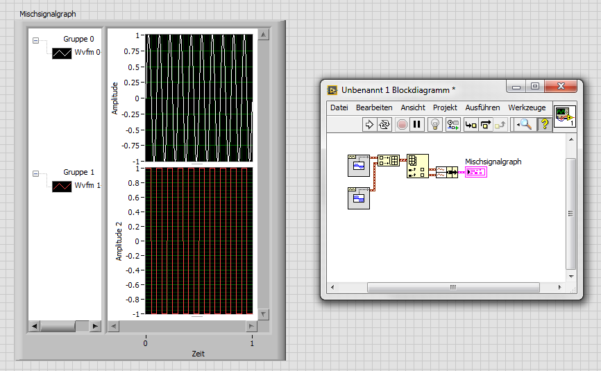
How to trace the temperature and voltage using the graph of Mixed Signal
Hello
I use the NOR cDAQ-9178, module NI 9214 (temperature) and the module NI 9201 (voltage). My program allows the user to choose among 3 different tasks, Masurement of temperature, voltage, or both. When you select the task for temperature and voltage measurement, I was drawing all channels on the same graph. I was invited to separate channels of temperature and voltage and draw on a split graph, using the same category axis. I tried stacking, but could not control where each parcel channel went. I think the Mixed Signal graph would work well. Everything works and records all the data of the channels to the files, but my plots appear not on the graph, although I can see the change in scale numbers. I think I can use the cluster incorrectly. Can someone tell me what I am doing wrong? I selected the 'Plot Visible' option, but the plot is not always displayed. I've attached a zip with all the screws needed to run my program. The main VI is "Voltage_Temperature_SingleTask_Measurements_MAIN.vi"... but everything must be downloaded to the program works. Please help... Thank you.

Hi mzhlb,
I complained only the expressVIs.
Why not use simple IndexArray function to get bots waveforms of your waveform table? (I faked it your DAQmxRead with functions SigGen).
-
Hello
Installation program:
2 x PCI-6602
Configuration:
Sampling the five PWM signals of 50 kHz using five counters (2 on a map) and three on another for about 10-15 seconds by recording continuously.
All meter tasks are configured for DMA transfer.
Problem:
I get 200141 errors from time to time.
Question:
I tried to increase the size of buffer and all tasks of meter are set to DMA. In the error message the last suggestion is to "divide the input signal before taking the action. I don't understand this suggestion. What is meant by "split the signal before taking the action?
I am open to other solutions to the problem.
/Mola
Yes, I know that the 2 MB/s sound do not like much, but it's a way of high load very low tolerance to try to get 2 MB/s. You have 5 DMA controllers to negotiate access to the bus and each transmits only 1 or 2 samples of 32-bit whenever he gets access.
I've seen published baseline data where the maximum sustained rate was< 1="" million/sec="" (don't="" recall="" if="" it="" was="" mbytes="" or="" msamples). ="" as="" i="" recall,="" finite="" acquisition="" mode="" allowed="" higher="" rates="" for="" shorter="">
Ah yes, here is a link that leads to the other links. See the section on "The counter of the FIFO" in the first message. Do you see a * very * significant difference in the performance of the M series for the series X-series. Here are data for counters of the E series. (It is fair to note that the comparative analysis was conducted with a much older PC hardware). For the 6602 counter chip was designed between E- and M-series series, so you can probably expect performance in-between.
Also note that the benchmarks seem to have been done with a task of window unique tent of owning all the bandwidth PCI as possible. Since you would have 5 tasks they negotiate access, you lose definitely even more overhead. In addition, for fair comparisons, your 50 kHz PWM would act as a measure of 100 kHz since you have 2 semiperiods to DAB per cycle of 50 kHz.
Now that I've seen benchmarks once again, I am convinced that it is a no-go for you with just the 6602. The good news is that the series X-series seem able to yet more ridiculously than I remembered.
-Kevin P
-
How do I get the analog input signal and send it to output analog (real time)
Hello world
I do a simple task in Visual C++ and I use PCI-6221(37 pin).
Basically, I want to send the same signal of "analog input" to the "analog output".
at the same time (or almost), to make real-time application.
Can someone provide me with sample program please.
I would be grateful if you could provide me with the great tutorial that explains
step by step everything about NOR-DAQmx for C/C++ programming.
Best regards
Khassan
This is my code in C++, you can optimize it if that seems too messy. This code reads the analog input signals and exports it through the analog outputs.
To make this code additional work of the directories include and library directories must be added to OR.
I hope it helps someone.
#include
#include
#include "NIDAQmx.h".
#include#define DAQmxErrChk (functionCall) {if (DAQmxFailed (error = (functionCall))) {goto error ;}}
int main (int argc, char * argv [])
{
Int32 error = 0;
TaskHandle taskHandleRead = 0, taskHandleWrite = 0;
Read Int32 = 0;
float64 context [1000];
char errBuffRead [2048] = {'\0'};
char errBuffWrite [2048] = {'\0'};
bool32 done = 0;
Int32 wrote;DAQmxErrChk (DAQmxCreateTask("",&taskHandleRead));
DAQmxErrChk (DAQmxCreateAIVoltageChan(taskHandleRead,"Dev1/ai0","",DAQmx_Val_Cfg_Default,-10.0,10.0,DAQmx_Val_Volts,NULL));
DAQmxErrChk (DAQmxCfgSampClkTiming(taskHandleRead,"",100.0,DAQmx_Val_Rising,DAQmx_Val_ContSamps,0));
DAQmxErrChk (DAQmxCreateTask("",&taskHandleWrite));
DAQmxErrChk (DAQmxCreateAOVoltageChan(taskHandleWrite,"Dev1/ao0","",-10.0,10.0,DAQmx_Val_Volts,NULL));
DAQmxErrChk (DAQmxCfgSampClkTiming(taskHandleWrite,"ai/SampleClock",100.0,DAQmx_Val_Rising,DAQmx_Val_ContSamps,1000));DAQmxErrChk (DAQmxStartTask (taskHandleRead));
DAQmxErrChk (DAQmxStartTask (taskHandleWrite));While (! fact &! _kbhit())
{
DAQmxErrChk (DAQmxReadAnalogF64(taskHandleRead,1,10,DAQmx_Val_GroupByScanNumber,dataRead,1000,&read,));
DAQmxErrChk (DAQmxWriteAnalogF64(taskHandleWrite,read,0,10.0,DAQmx_Val_GroupByChannel,dataRead,&written,));
}
_getch();Error:
If (DAQmxFailed (error)){
DAQmxGetExtendedErrorInfo (errBuffRead, 2048);
DAQmxGetExtendedErrorInfo (errBuffWrite, 2048);
}
If (taskHandleRead! = 0){
DAQmxStopTask (taskHandleRead);
DAQmxClearTask (taskHandleRead);
}
If (taskHandleWrite! = 0){
DAQmxStopTask (taskHandleWrite);
DAQmxClearTask (taskHandleWrite);
}
If {(DAQmxFailed (error))
printf ("error DAQmx: %s\n",errBuffRead); ")
printf ("error DAQmx: %s\n",errBuffWrite); ")
}
printf ("end of the program, press the Enter key to quit\n");
GetChar ();
return 0;
} -
4 counter of entry & 6 the input signal HELP
Hello friends,
I have a small problem, would be great if someone can help me.
I use the counter inputs on my CQI data. Harware to measure the pulse of my sigal entry width.
Since the material has only 4 entries of meter I can connect 4 channels, but I want to measure the pulse for 6-channel width.
Is it possible to use the 4 available counters and measure 6-channel?
Thank you
Kind regards
REDA
In my example (very basic), you can just increase the timeout for ~ 10 + seconds to ensure you acquire the pulse. It is possible that the pulse is not present in the ~ 10 + second timeout, you must also handle the timeout error, so it is not wrap around back through the shift register and prevent future readings to run.
Of course, the downside of this is that it could take up to ~ 60 seconds in order to gain all 6 channels in the worst cases. The example was really just intended to show how we can use a single meter to acquire multiple channels in the estate.
The best way to do it with meters would be to run tasks in parallel (up to) 4 meter. The first 2 tasks to finish with their initial acquisition should then measure a second channel. This could still take about 20 seconds if no signals are connected however.
If you want to trade a lower resolution of measurement (and memory use more) for a lower upper limit on the time of measurement you can acquire a second time 10 window using the call digital inputs instead and use software to determine the duration of the pulse by analyzing the acquired table.
Best regards
-
Should I reset the FPGA FFT when changing the input signal?
Hello
I have an application based FlexRIO where I do FFT on several incoming signals. The signals will be ranked so that I get first for example 4096 samples of Ch1 and Ch2 4096 samples, etc. This means that I don't have to do it in parallel of the FFT and I would like to reuse the implementation of FFT and windowing to reduce the use of resources.
I intend using the VI Express followed by the Express VI of FFT window scaling
http://zone.NI.com/reference/en-XX/help/371599J-01/lvfpga/fpga_scaled_window/
http://zone.NI.com/reference/en-XX/help/371599J-01/lvfpga/fpga_fft/
and I'll use them inside a SCTL.
This figure comes from the section using the FFT and help illustrate the issue:
There is a discount to zero terminal for the fenestration and the FFT VI.
Are there internal registers in the windowing and FFT which force the image 1, image 2,... from the same signal or is it possible for the first entry in a framework of Ch1, the next frame belonging to Ch2, Ch3 gaze and so on and always get reliable results?
Another way to ask the same question: if I have to reset the window and FFT when changing the input signal?
Thank you
Anders
Hi Cyphish,
When using the FFT of the LabVIEW FPGA vi express and windows nationwide express vi calculations are make it point by point so there will be no problem when going through different types of measures. Therefore, you should have no problem with your application.
Best regards
Menelaos.K
-
How the input signal updated step in simulation?
Hello
I have my own model of transfer function. I did first with Matlab/Simulink simulation and succeeded. I use the Signal Generator in Simulink to get out my custom step signal. I modified my step so signal to:
t = 0 y = 0
t = 0.1 y = 0
t = 0.1 y = 50
t = 10, y = 50
t = 10 y = 65
t = 30 y = 65.It's the kind of staircase input signals. Now, how to build such this approach custom signals to be fed in my transfer function. I tried the function 'Not of Signal' of the 'Simulation', but I can only get the 50 and I don't know how to add more "staircase" in my input signals. Could someone help me?
-
create 4 pulse digital output at the base of the ttl input signal
Hello
I am a beginner in Labview and would welcome advice on how to solve the following problem.
I'm setting up a train of pulses TTL and would like to send in Labview as input. Each falling edge detected on the input signal, I would like to as Labview to generate 4 pulse digital output. For each output pulse, I would like to be able to specify the period and duration. The image should illustrate more clearly, with the figures showing the expected scale.

System: NI PCI-6733 data acquisition card, Labview 8.5
My daq card has 2 timers 24-bit and 8 e / s digital, but I don't know what the best approach is to create between the pulse output of 4 to 8 of this precision... should it be handled at the hardware or software level? And how would I go about it
Thank you
-Sidney
Hi noli.
I found the problem, in fact PCI-6733 support only avoiding the digital output. The timing of software is limited to 1 kHz in case better.
I'm sorry, but this function is not possible with a PCI-6733.
Concerning
-
Hello everyone.
I'm very new to the hearing, I have a question please. I watch a tutorial that explains the counter input Signal. When I right click inside the box to level it is low-Out.
Thank you very much.

UPDATE: I HAD TO HAVE THE MICROPHONE ATTACHED TO MY COMPUETR. I DON'T HAVE THE MICROPHONE CONNECTED TO MY COMPUTER.
Yes, you need a front entrance you can it meters.
-
HP 2509 b monitor guard displaying "Input Signal Out of Range" and then go to sleep.
I went on vacation and shutdown my computer for 2 weeks. My monitor worked great for a month before. I came home last night and turned on my system this morning. Now I get a white message in the middle of the screen with "input out of range Signal. Change the settings for 1920 x 1080 at 60 Hz"and then the screen goes to sleep. I can turn the monitor off, wait a moment and then turn it back on again, but continues to repeat the same thing. I checked and the screen is already set to 1920 x 1080 at 60 Hz. I use VGA and have the default positioned like this. I followed the guide to troubleshooting online for this error, but it did not help. Can someone tell me please how to fix this?
Finally, I got this figured out! Here's what I did.
Control Panel
Display
Parameters
Advanced
Intel(r) Graphics Media Accelerator Driver
Graphics properties
Display settings
Expansion of the display
Chosen at this stage full screen (no border) instead of "maintain proportions"
As soon as I put this the error screen disappeared! Can someone explain to me why this adjustment has been around? I would like to know.
Thank you all for your help.
Maybe you are looking for
-
Could not find the button firefox on windows 7
don't have firefox button that gives me all the options
-
I disconnected all devices I have a Skype (home and office computer laptop, smartphone) application and always contacts me signed see and send IMs and make calls. Please help me solve this problem.
-
Computer turned on but does not
I have a desktop running Windows XP Pro SP3 that is constantly lit. My screen saver is set to off after being idle for 20 minutes. Opportunity (maybe once a week) when returning to the computer, it it will activate. Moving the mouse, punching keys.
-
run the server in vmware under the router (shared ip)
Hi im using router (shared ip) andboth the host and the guest os is xp pronow I can run the Web server on the host operating system after that I have a lot of hard workbut I want to move the guest from the host computer operating system serverin the
-
How do I * definitely * disable the USB bootable media
Thus, in WinPe and load HAPI. I put successfully boot optionsCCTK BootOrder - bootlisttype = UEFI - disabledevice = uefi.1, uefi.2 - valsetuppwd = On the next reboot, my bootable USB media is removed from the list of startup, but only when the usb k