the relay control data acquisition
I am creating a vi that controls (press and release) several relay using a USB 6501 data acquisition. This should be a task relativily easy but I get flumoxed by errors. I tried to use the examples, but I get an error telling me that I need to use the mode of generation 1 sample (on request). Help, please
Sure. The easiest way is to have a DAQmx writing followed by a function of delay, followed by another entry, followed by another period. Simply plug the error links in order to control the flow of data. However, the VI would be insensitive so you can use a state machine or function elapsed time so that the VI can be stopped without waiting for waiting for him at the end.
Tags: NI Software
Similar Questions
-
Is it possible to change the name of data acquisition device?
Hi all
Is it possible to change the name of device of data acquisition in a pragmatic way?
I wish I had at the beginning, when I start the data acquisition control a name that my .net program assigns to the DAQ card. Is this possible?
Thank you
Virginia
Ashly thanks!
Virginia
-
Digital relay of data acquisition
Hello
I quickly ask you questions. Can I connect several relay digital for single block scb - 68 (data acquisition is: 6321 PCI)?
With Labview, I want to enable or disable each of these relays. Is this technically possible? because never, I have connected several sensors to scb - 68.
Each relay acts as a binary switch to a motor brush continuous (3-12 v and RPM motor voltage: 11.5 krm with weight)< 80="" grams).="" the="" dc="" motors="" will="" receive="" power="" from="" external="" dc="" power="" supply="" unit.="" so="" the="" power="" for="" the="" relays="" (i="" am="" thinking)="" must="" be="" from="" daq.="" but="" i="" know="" daq="" can="" supply="" only="" very="" very="" less="" current.="" i="" am="" trying="" to="" source="" out="" if="" i="" can="" find="" relays="" that="" run="" with="" very="" current="" (which="" could="" be="" supplied="" by="" the="" daq="" itself)="" can="" you="" suggest="" me="" if="" this="" is="" possible?="" and="" also="" any="" information="" or="" source="" for="" the="" required="" digital="" relays="" would="" be="" lot="">
Thank you
MSC
-
How to increase the speed of data acquisition?
Hey, currently I using 6210 OR of data acquisition and control switch. I used labview to periodically check the 7 switches and read data from 7 channels in the meantime (1 sample on request). I ran 70 loops for 10 groups of data, the cost of the time looked like 2.2 seconds.
I would like to end a 700 loops in 2 seconds, is it possible to improve?
Thank you
PEM
Look at the Terminal stop of the DAQ Assistant Express VI. You are starting and stopping of the task for the acquisition of data on each iteration of the loop.
Starting from the help file:
Stop
Specifies to stop the task and release device resources when this Express VI ends execution. For ongoing tasks, this entry is FALSE by default, which means that the task is running until the application terminates. To stop the task, you can use the device again in the same application, wire control wire you the Conditional stop this entry to the same terminal of the while loop. For single-point and finished tasks, this entry is TRUE by default, which means work stoppages after all samples are acquired. To optimize the performance of single point when using this Express VI into a loop, wire control wire you the Conditional stop this entry to the same terminal of the while loop.
Also from the help file:
Continuous single point of entry or exit, the of VI Express DAQ Assistant cannot allow optimal operation. See Acq & chart voltage-Single Point optimization VI in examples\DAQmx\Analog In\Measure Voltage.llb for an example of techniques to create more powerful applications, single point of I/O.
-
The reading of data acquisition via tcp
Hello
I am building an application that controls an acquisition of data via tcp.
I have a JAVA program that communicate with labview, give a command and data acquisition starts. (So, I read the correct Java data at Labview)
My problem is if I try to read data acquired by data acquisition (continuous sample 1 k samples), I've read strange values.
I transform of double values in the string and send it via tcp.
How can I read it in Java? What type of socket should I use? What is a rate problem?
I also tried to transform small/big-endian byte order, but it does not work.I enclose a sketch of this part of the application.
Please help me, I try for 2 weeks!
Thank you all...I find the solution in the lavag forum.
I post here, if it can help someone.http://lavag.org/topic/16359-sending-LabVIEW-data-via-TCP/page__pid__99983#entry99983
-
Configuration of the two of the same model data acquisition
Hello, community of NOR.
I'm an intern in mechanical engineering with experience in base with LabVIEW.
I would like to speak to OR directly on this issue, but I don't have a service contract and my company wants me to understand this before you buy LabVIEW.
I hope that someone has experience about my question, and I would be very happy to help.
We intend on purchasing an expansion card for our acquisition of data (OMB-USB-2416), but unfortunately it is offline and no custom would not happen in time.
So, I need LabVIEW to read voltage HAVE two of the same model of data acquisition, which would amount to about 30 channels.
Is this possible with LabVIEW?
Thank you.
Measurement computing says that the "physical channels" dropdown list is automatically filled in once both devices are configured.
-
delay between the trigger and data acquisition
Hi, I use NI SMU-6368 as a tool for data acquisition. In my experience, I use an external digital trigger to start taking measures of a thermistor.
However, before the experience, I want to know the time that elapses between the detection of the trigger signal and data acquisition start time.
Is there a way to do this?
Here's the kind of thing I configure to get an accurate measure of time of t = 0 trigger signal to the
the actual first A/D conversion. It may be too much for a measurement of the temperature, but you should get
the right track.
-Kevin P
-
BNC-2110, 6023E PCI card and Labview V9.0: sensitivity of data acquisition (change more little detectable voltage) is 0.002V
Hi, I use the software/hardware above to read a voltage of a potentiostat world Precision Instruments No..
I'm trying to record changes in voltage as low as 0.0003V but using the wizard DAQ, I seem to be limited to a sensitivity of 0.002V. This is the limit of real sensitivity or have I missed something?
Any help would be greatly appreciated.
Hi DCAM77,
Thanks for joining the forums!

The PCI or 6023E has a 12-bit ADC. In other words, it can make the difference between 4096 (2 ^ 12) different levels within the range of cards. The card you have has a selectable range by ± 10 V, ± 5 V, ± 500 mV or ±50 mV software.
This means that the minimum detectable variation will be 4 mV, 20 mV, 244 µV or 24, depending on the chosen range µV.
You should be able to use the ± 500 mV or ±50 mV to get the least significant bit (LSB) value, you need, even if it means that your signal is located between these values. If not, then you need to consider other materials to the application, or the addition of external circuits across the signal.
-
TDMS write a comment in the middle of Data Acquisition
Hello
I am currently using TDMS for my data record. Currently I log data from a Keithley module via GPIB connector.
Essentially, I want to save data in intervals and during the recording of data, I want to have a comment section where I can write the changes that have been made.
It connects every minute and I want to add a comment in the minute 5 for example. What is the right way to apply it.
Thank you
I would use a loop that is dedicated to writing in the PDM file. You can then send commands/data to this loop in a queue. You could a single command to write your DAQ data and another for observational data. I would connect all the data data acquisition in a group and observational data in a second group. That will make your file much easier to understand.
-
Information about the properties of data acquisition
Hello
I'm William, a student from Belgium (technical measure and control). For my thesis in June, I need to make a comparison between the USB 6008/6008 and myDAQ device. I must do this based on the specifications of the devices. Specifications of several I found in the manuals are very interesting, but I don't know what they mean. Can someone explain it to me as 'temporal resolution', the 'input and output resolution' and the 'steering control. Are there simple experiments with Labview to show the difference of several between two DAQ devices?
with friendships.
William
Hello William,.
I don't directly know specific tests about the comparison of the time resolution for these cards.
Of course, you are always free to do these tests yourself and share them with us.
-
Write equations on the front for data acquisition
Hello
I was wondering if its possible while a VI is running for:
- Write an equation custom on the façade.
- Use the equation on data acquired since the VI is running.
- Draw the calculated data.
See you soon
I think you should take a look at the examples (help > find example... > tab "search" > try with formula or equation), it is one that shows in a simple way, look here: C:\Program NIUninstaller Instruments\LabVIEW 2011\Examples\measure\maxmpl.llb\Waveform Formula.vi using generation
hope this helps
-
Change the speed of data acquisition
I record the temperature using a PSC-2120 (cFP-TC-120 + capable). Could someone please explain me how to slow the acquisition of data to make each minute rather than each MS that's for two reasons. First the data file are produced get so large that excel do not all data from a spreadsheet and Notepad can not open them. I had a .lvm file which was more than 700 MB of the day to the next. Second, the data is displayed on a graph when it is saved (left hand on the vi graph), but he is drawn as a variant rates. Sometimes it's every millisecond, others it's every few seconds.
I enclose my VI, but I can't reach my text file is too lig must be downloaded (it was after 10 min data recording)
Thank you
Chaz
Hi Chaz,
Thanks for the post and I hope that your well.
To change the rate of datalogging, you will need to use the timing of the loop. You can do this with a (better) timed loop or with vi timing structure (for example, wait until the next multiple) in the loop (good). This knowledge base article, he explains in detail,
How to set the analog input of my FieldPoint Modules rate?
http://digital.NI.com/public.nsf/allkb/3DCBB324D23FD637862571320066AA7A?OpenDocument
Hope this helps,
-
the scale of data acquisition and data entry error
I have a USB 6211 camera set to MAX for 11 different channels: the first 10 channels are configured with a scale factor of 2 while the last channel is configured with a scale of 1. I connected battery 9 V for the first two channels, ai0 & ai1, (level 2) and the last channel, AL10, (1 scale). The input pins were 15, 17 and 20 for input voltage with pin 28 connected as a reason. Then, I checked the feature in MAX. Surprise! I expected to see 18 volts for the first two channels and 9 volts for the last channel, but much to my surprise I got all channels showing data about 10.86 volts and the last channel showing a value of 7.79 volts! How is it that I see the values for channels not connected! In addition, why are values of cable channels so screwed up! With a 9 V battery and a scale of 2, I expect to see 18 volts, not of 10.86, and where the 7.79 volts for the channel which has a scale of 1! If I run MAX continuous mode instead of the sample N mode I get a few other strange results: I get a single horizontal line and 1 sinewave! It's amazing because I have a 9 volt battery connected to the unit! I don't even how arrays of the VI that uses these signals is like since they are all screwed. Will you please advise me on this one because I'm completely stumped.
-
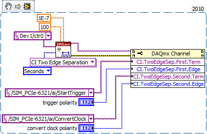
Hello
I want to generate the continuous signal and at the same time I want to read that signal that I generate using a single card DAQ. I want to generate signal and the received signal is synchronized and in phase.
I looked at several samples on the sync, but it quiet confusing. One using the same clock of entry while the other use a trigger to start. I use the PCI-6024E DAQ card.
Can someone help me in this regard?
In two of these screenshots, the task to HAVE started first (that's what you want, because it is the task of the slave).
Typically for AO, you can simply write a unique period of your waveform, and then regenerate again and again. Your waveform would be preset before the task starts. If you need to update the waveform on the fly according to enter programming during execution of the task, you would disable the regeneration. In addition, if the wave form is such that it cannot be easily represented by a predefined buffer (for example, it is a strange frequency which is not a same ditch at the bottom of the sample clock), then non-regeneration is the way to go.
Best regards
-
The functions of data acquisition
Is there a built-in feature to detect and fill properties DAQ (channels PCI, I / AO, DI / DO channels, etx) for completely custom DAQ configurations?
Here is my approach.
Maybe you are looking for
-
MY scree of iphone break and how to change
-
Working with USB high speed Interface Modul 2.7 in LabVIEW
Hello is there an example works with a USB high speed Interface Modul 2.7 in LabVIEW? The EGG is a "Cypress CY7C68013A-56PVXC» Thank you Best regards, patrick
-
Hello I have pluged GPIB-USB-HS to Agilent Network Analyzer and Analyzer GPIB address is 17. I can find it in MAX. But I can not find it in Labview VISA. Please help me to fix it thanks. BTW, all information Setup in MAX GPIB is grey, I can't change
-
Can I remove the old updates in order to recover space on my computer?
Can I delete old files to update such as updates from 2003 to 2007 for example
-
connection printer to the new laptop
My printer is connected to the wireless network, but I try and put it on my new laptop (windows 7), that it says cannot find every time. I checked that all on the same network and they is, firewall off as well - so frustrating How to connect existing