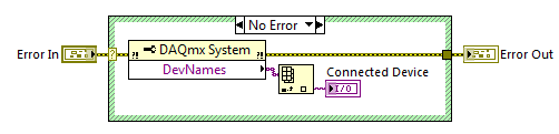
There is no entries or exits on the DAQ assistant to connect to
Hello world
I'm new to labview and have encountered difficulties with the DAQ assistant. I'm under v8.0, v8.7.1 OR-DAQmx labview and have an acquisition data PCI-6224 installed. It seems that every time I have let down the DAQ assistant (assistant of the instrument and data acquisition simulated has the same question) on the block diagram and configure it, it don't y no input or output that I can wire a control or an indiactor to. Y at - there a step I'm missing somewhere?
Thanks in advance!
Try to repair the DAQmx driver through control panels and see if that solved the problem.
How to uninstall or repair OR software?
http://digital.NI.com/public.nsf/allkb/AC6ED75D3D93375686256E8E00245F0D
Tags: NI Software
Similar Questions
-
Multiple entries to the DAQ Assistant
Hello

I'm doing my DAQ Assistant, in several (formed of an array) Boolean inputs where there is 1 digital output. (see attached software folder)
Physically, I want a valve to open and close at a certain pace, where the user can install/control this pattern until the program starts.
I think that the best way to do it is to have multiple Boolean values that the user can press or unpress.
Before that, I started, I tried with only Boolean 1 where it worked perfectly.
As seen on the attachment (error), it is possible to an easy problem to solve, but I just can't figure it out, I'm stuck at my already made solution.
I use USB6008.
I hope that there is a gentle soul who can help out me.
Best regards
Kenneth G. Vejen
Hi Kenneth.
When the output to the generation mode is set to "sample 1", which means that whenever you call the DAQ Assistant will generate 1 sample. In order to generate 5 samples, you must therefore call 5 times.
I have attached a modified version of your VI, which shows a way to archive it. However, be aware that the samples will be generated fast and not at 100 ms note your loop runs. It depends on your application, if it is as you want samples to be issued.
-
Hi all
This should be a pretty simple question, but I can't seem to find the answer online and currently do not have the functionality to test this:
I'm using LabVIEW 8.5 and have a VI that imports data from sensor through the DAQ Assistant. In the configuration tab, there is a range of signal input. What happens if my sensor exceeds this range? I get a warning? The default value is the maximum (or minimum)? I was interested in writing a code to display an error that I approach the limits of this range, but did not know if I also need to include code to display an error if the scope is exceeded as well.
Thanks for the help,
Tristan
Hello, Tristan,.
The behavior depends on the selected range and the device you are using.
If you are using a device with a single input range is valid, we will use this range, even if you set a smaller minimum and maximum in the DAQ Assistant. So, if your device only supports ±10V and you set the range to ±8V, you will still continue to get valid data after your top sensor 8V until what you approach 10V. When you reach the limit of the extent of your device, the output will be 'rail', and simply return the maximum value until the signal is less than the maximum value again.
Note: A device that is nominally ±10V usually has a go-around (such as ±10.2V) which are usually specced in the manual.
However, if you use a device with several ranges of entry then things become more complex.
NOR-DAQmx player will choose the smallest range that entirely covers the interval you choose. For example, suppose that your device supports the following input range: ±0.2V, ±1, ±5V, ±10V and you choose 0V - 3V as the range in the DAQ assistant. The NOR-DAQmx driver will focus on the input range and the list of the entry lines that your hardware supports and choose the smallest encompassing the entire range that you set. This would be the ±5V, because this is the only beach that contains up to 3V. Thus, all between ±5V input signal is returned and none outside this range will be 'rail' to the maximum or minimum value.
We do this because using small beaches make more efficient use of the resolution of the ADC. So, we try to use the most effective range based on what you ask without picking up a range that will make you miss data.
Let me know if I can clarify it more.
-
New Daq with the Daq Assistant in the filtering code
Hei,
I have a NI USB-6225 DaqMx I used a couple of years. When I started with LabVIEW, I found the Daq Assistant to the best way to measure the voltage with my Daq etc. My company has purchased another DaqMx NI USB-6225 and now I have a big problem: the Daq Assistant in my old Vi does not work with the new data acquisition. I understand why there is this problem, but I do not know how to solve. I found this code on the forum who finds that Daq is connected:
The problem is that Daq Assistant do not have an entry for it, and it gives me an error if I try to run the code with a different device than the original, I used when I created the code.
Is there a way to solve this, so I don't have to convert all the Assistants Daq normal code?
Hello again,
two options:
(1) as the old software is related to 'Dev1' you must rename your new device to this alias and skip/rename the old device (and lack).
(2) rewrite your old software does not become is not dependent on the name of the alias for the data acquisition card...
It's your choice!
-
Calibration of thermocouples in the DAQ Assistant, using data from spreadsheet?
Hi all
For my first application LabVIEW, I'm looking to automate the calibration of thermocouples by measuring their response at different temperatures in a dry well Sizer. I get temperatures of thermocouples six by SCXI 1303/1102/1600 and have six channels put in place in one of my subVIs in the DAQ assistant.
I compare these values to temperature calibrator that I am acquiring by VISA series in an other Subvi. All these values are written in a .csv file.
Can I import these data into the DAQ Assistant to use for calibration? Is there a simpler way to associate with the channel calibration data? Currently, I could manually copy - paste the cells on the worksheet in the calibration sheet, but that seems just silly.
If there is everything that I could provide to help solve the problem, let me know!
Thank you!
Hi Zoysiamo,
It is possible to automate the calibration screws DAQmx at a lower level, in particular the DAQmx channel property node. Using you can specify advance nationwide and the values on the scale for your channel. I recommend you take a look at this example of the community. The property node configuration will be similar to, as illustrated below:
-
I've just updated LV 2009 SP1 LV 2010. I use a LV 32-bit on a 64-bit computer.
When I open the DAQ Assistant, I get a pop up window that says "LabVIEW: an exception occurred in the external code that is called by a function of the call library node." This could have corrupted memory of LabVIEW. Save all work to a new location and restart LabVIEW. VI "Advanced Timing.vi:1" was arrested in node "" a call to "get of DAQmxAssitant_DAQmx IO Info.vi of control.
If I hit OK, DAQ Assistant is locked up, if I use the Task Manager to close the LabVIEW vi breaks down.
I already reinstalled 9.5.1 DAQ device drive. without success.
There is no such version. The most recent is 9.2.2.
-
Precise triggering voltage input and output generation in the DAQ Assistant
Hello
I wonder if anyone has come across a simular problem with the synchronization of input and output voltage. I use a box 11 LabView and NI USB-6259. I have been using the DAQ Assistant to configure the input and output channel. In particular, my task is to generate a single rectangular "pulse" as the output voltage to drive a coil and once the pulse went to get a signal from a sensor of magnetic field and get a power spectrum. This means that the order and the time during which the DAQ Assistant is used is extremely important. For example, the output voltage channel must be opened first for 2 seconds. Subsequently, the channel of input voltage must be open for 1 second, in which the sensor signal is obtained and post-processed. Only after these tasks are performed in this order he can can be repeated in a loop until the experiment is over. I don't know how to trigger data acquisition assistants (one for entry) and the other for the voltage output correctly. Y at - it a trick?
See you soon
Michael
Hi Dave,.
Thank you that I wired the error strings but the timing issue was unrelated to it. In the DAQ assistant, I simply had to choose the continuous aquistion of the 'samples' methods 'N-switch' for input and output voltage and all works fine now.
Thanks again
Michael
-
Is the DAQ Assistant compatible with LabView7?
I am equipped with a LabView7 and a NI DAQ - 6015 Pad and am trying to monitor the temperature with two thermocouples. I searched some tutorials online, but most suggest using assistant DAQ, which is not listed in the section of my functions palette entry. I have downloaded the NOR-most recent DAQmx driver who is supposed to be compatible with LabView 7.x. I don't know if this means that it is compatible with LabView 7.0. I still do not see the DAQ assistant appear.
Any help or suggestion (about DAQ assistant or how to program in LabView7 to solve my problem) is greatly appreciated!
Thank you.
It looks like the DAQmx latest version is 8.1 which will work with LV 7.0
See here http://digital.ni.com/public.nsf/allkb/97D574BB1D1EEC918625708100596848
-
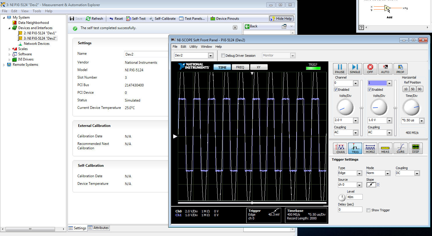
I am trying to create a development machine, where we can test the new code without using our physical hardware. I followed this guide to set up a system of simulation. I get to step 3.2 b, but the device does not appear in the DAQ assistant. MAX, the device self test and gites calibrated successfully, and when I open the test panels, I see some sort of signal. I guess that's a default entry simulated since I didn't that device to look for anything? Note that two devices, I am creating the show upward into the devices section and Interfaces, but that, even after running auto calibrate, automatic Calibration date is not yet specified.
When I try to test the device and create a voltage according to the guide, I can't see a device in the creator of data acquisition task.
Steps 1 and 2 of this guide are of course met. Step 3 is not, but this is not surprising because a simulated device is in device in any case manager. Also, I'm not under RT, so step 4 is satisfied.
Someone at - it ideas?
That would be because the PXI-5124 is a digitizer not an analog input device. You must use the NI SCOPE not NOR DAQmx driver
-
How to create different types of analog inputs without using the DAQ assistant?
Hi all
I would like to create multiple entries multiple analog channels of type... I mean I want to have the voltage of 5 and 2 channels of temperature...
However, I am not using the DAQ assistant. I use "create channel" vi.
Can anyone suggest me please how to do / I submit my VI for reference... I have 5 tensions, and 2 temperature characterized as showing these 2 two separate graphics...
-
Trigger of the DAQ Assistant to loop For
Hello
I am very new to Labview and assigned to a writing program. I've been through the academic tutorials, but they only cover basics. What I'm trying to do is to use a 100 County loop interactions For and turn at the exit of my Daq Assistant power to every interaction.
Is this possible to do?
Kind regards
Andy
andywileman wrote:
Is this possible to do?
Yes... Oh, you want to know how? Use a shift register to keep track of your current state of the output. Use the do not reverse the value of each iteration and write this value in your data acquisition.
-
USB-8451 does not appear in the menu of the DAQ assistant
Hello
I use a USB-8451 with LabVIEW 8.6 device. I installed the 1.1.4 pilots of this device and windows and MAX detect. I also renamed the alias and the status of the device is "this device works correctly.
The problem comes when I try to add a block DAQ Assistant to my project. I select the entry type, I want to have (digital line, although I've tried them all) and LabVIEW doesn't detect any device.
I tried to make a diagnosis with Panel Test VISA. Here, I assume that something is wrong, because when I run a viRead I get status of return 'BFFF0015h' in red letters... but I don't really know what that means. The LED on the device is green and flashes.
Thank you in advance.
It is not supposed to appear in the DAQ Assistant (and certainly won't NI-VISA) or if you have not read the Manual?
-
Hello, this is my first post here,
I've been wondering about this:
When you configure a new daq with the daq Assistant, is the resolution applied to the voltage / number of entries you define, or is it a fixed value per volt by channel.
For example:
I have a 6015 usb data acquisition, it has 16 inputs analog, 16-bit resolution 250 kech. / s 09:50 volts.
so is this as (2 ^ 16) / (16 * (-10-10)) = my resolution through volt?
or that this has nothing to do with the amount of channels,
If I want to measure more than 0 to 5 volts, my 16-bit apply from 0 to 5, or even more scale of data acquisition (which is 09:50 volts)
Thank you
Marco
You will get full-resolution 16 bits on each channel regardless of the number of channels is configured. Renault most are multi-plexed if your specification of sampling RATE in usually a global significance that you can only scan channels with a sampling frequency = MAX RATE / number of CHANNELS. Also, most NI Renault have a Programmable Gain amplifier on the front-end server, so if you specify a range of voltage smaller in your task configuration the amplifier will automatically increase the gain to use most of the possible BIT ADC. You see care device and for more details...
-
Recovery of the DAQ Assistant data acquired
Hello
I'm currently dealing with a continuous data using NOR cDAQ-9174 proposed acquisition and recording of analog input signals of a built-in three-measuring probe.
I built a simple vi using DAQ Assistant to acquire data and write to an output .txt - rather than .tdms using Signal Express.
On a day 10 cycle of data acquisition computer was mistakenly turned off - leaving the empty output .txt file. LabView recovered the VI cut and I wonder if there is a way I can access the data that has been saved by the DAQ Assistant which can be saved in temporary files etc..
I have no idea where that might be, since you cannot delve deeper down into the 'levels' of DAQ assistant as you would a sub - vi.
Just as a note aside to apologize my stupidity - I realize that all the data at the end of the writing task is stupid and completely avoidable... but I worked for a date limit.
Thanks in advance for any help you can provide.
Dan
The most likely answer is not, unfortunately. It looks like you were a table of data at every point of the construction and then measure he writes at the end. In this case, unless you have explicitly recorded data in a temporary file, it is located right in volatile memory, waiting for you to do something with it.
I realize that this isn't what you want to hear, as it comes to the time of submission of draft / year...
If you post your VI (preferably version LV2012 or below), I can have a look to see if there is anything obvious.
-
201003-error occurred in the DAQ Assistant
Hello. I use "cDAQ-9178" and "NI 9215" and "NEITHER 9402" are added on. "
However, when I run Labview code, "Error-201003" occurs.
{
Device not available. Possible causes:
Device is no longer present in the system / device is not powered.
Device is turned on, but was temporarily without electricity / device is damaged
}
(Error appears as the 1st and 2nd figures below).
(Plans of logic is the figure below).
Thank you.
I could be something with the pilot
Check this box:
Error 201003 to the MAX test panel or all by running the DAQ Assistant
http://digital.NI.com/public.nsf/allkb/5413F392D88326148625746B006745C5
In this forum, they speak the same error:
Spontaneous error code 201003 for acquisition of data PCI configuration
http://forums.NI.com/T5/SignalExpress/spontaneous-error-code-201003-for-PCI-DAQ-Setup/TD-p/830707
Maybe you are looking for
-
Solution for Bluetooth PAN server configuration
Task:-Internet on Bluetooth PAN profile-Connection for laptop (Toshiba Satellite A300 1 2 (WinXP SP2) with Sony Ericsson K810i with BT PAN)-Computer as a server of PAN (!). Lance PAN Mobile phone connection-> computer.You can use internet to mobile p
-
What will be the last versino of flight simulator be released?
I can't wait to buy the latest version of Microsoft Flight Simulator. May I know when will be the exact release date, where it can be purchased and what is the name of ther version. Please include the requirements of the program as well.
-
I have two email address but a friend, who I asked for help, sent many of my answers without paper that I use to communicate with family and friends. Now, I have more 2 000 not open emails and it grows even more every day. Also places like Amazon,
-
Download hp photosmart essential. Where to find a safe downloadsite for a Swedish version
My Hp Photosmart Essential suddenly abandoned - the computer has tried to find a solution, but diddnt. I found a site for a Swedish version. But how do I now that it is safe. HP have such a site? My needs are simple.
-
How can I reinstall the CS5 download?
I want to stop my subscription program since I am now retired, but still be able to use my software for personal use from time to time. My last box software was CS5 Design Premium (which I threw away) so I downloaded it. When I try to install it, I g