Three-phase Measurament
Hello world
I'm trying to measure the phase and the power factor for a three-phase motor. The problemn is that the engine runs with 480V and the SCXI module I can only manage up to 300 Vrms. I think the use of some voltage transformers to step down the voltage and then connect it to the SCXI module. If I do this, will this affect my angle factor and the phase power?
Assuming that this configuration works, how can I find the phase in every thread? Is it possible to run all samples at the same time and then make a few comparisson between their plots to measure this?
Thank you!
Kenny Caldas
This device must be end. put the rest of your budget in good processors.
Lynn
Tags: NI Software
Similar Questions
-
Low cost brushless three-phase amplifier
I use cRIO to request control phase brushless motor three specialty. NOR has a NI 9505 module for control of motors brushed. I have not found one for brushless motors. There are a lot of controllers of third brushless motors integrated in the market. Will not work for me. I need to directly control the cRIO output transistors.
I guess I'm looking for a low-cost three-phase bridge amplifier. The low cost is necessary because it will be part of an OEM product. The engine is rated at 40 volts and 10 amps.
Does anyone have any suggestions?
Here files gerber and the source files of origin for the Council that I built. It was designed by EagleCAD, and the final design is drive1.brd. I don't think that there is an error with this review of the Council, it should be good to go if you built it this way.
Others that some of bridge-on-chip solutions that I found, there was no option for the units silent, low-power (disks without built control logic in). Because I wanted to do my own development of control algorithms, it meant that I had to either crack open a trade route or build my own. Of course, I went the second route.
Good luck.
-
Synchronous channel multiple acquisition USB-6259 (phase measure)
Hello!
I want to create a user-signal (1 k at 20 kHz) in SignalExpress, generate it with the case NOR USB - 6259 BNC and measure with the same device after that the signal has passed a DUT I need the answer for a fixed term.
For the moment, I'm trying this: I connected the output via a Y-coax analog (length 1 meter) to TWO analog inputs.
Because the input channels have been grouped with the add a channel button, the data acquisition should occur almost synchronous.
However, sometimes the phase response is zero (cause as expected the two signals must be equal), but sometimes it "jumps" (especially when I am running the new project) and increases or decreases linearly on the frequency (so there is a time difference between two measured signals).
I don't think that running is the problem here, because referring to the manual, it's about some µseconds and I have not yet change the range of voltage between input channels. Furthermore, the magnitude response is fine.
I has not yet perform to synchronize the input channels with the output of the channels either, but first I would be recognizing a solution for the entry-entry-synchronization, (I don't mind if it is implemented in LabView).
Thanks in anticipation, Daniel
Hello Daniel,.
the M-Systems Series DAQ using a switch to sample multiple channels. So you have to take the time to switch into account when
you do measures such as phase shift of two signals.
I took your project Express of Signal but also created a LabVIEW VI to double check, and you can see exactly the same lag between the two
sampled signals. If you want to measure the true phase differences, you have to use a device of simultaneous sampling like S or DSA series devices (there are more a few others).
concerning
MArco Brauner NIG.
-
Three-phase engine model problem AC...
Hello, is it possible to use the 3PH_Motor of the family OUTPUT_DEVICES located in the Electro_Mechanical group but with a model modified to Spice that uses only the data printed on the nameplate? I ask this question because I simulate the power factor correction using a field of 10 engines rated at 110 kW each, for my thesis, but I need to the R and L of the windings in order to use the default template and I can't find these values in the catalogues.
Thank you in advance and I hope that there is a way to solve this problem...

I guess that you are looking for an induction motor.
It would be simplistic to model a with a fixed R, support the induction motor (in the Multisim V12 we actually removed the 3PH_Motor and added instead a more realistic dynamics model based on a more realistic set of parameters). An induction motor is in many ways like a transformer. Therefore, you must the inductance of magnetization, inductors of leak of the rotor and the stator and rotor and the stator resistance. You may be able to contact the manufacturer to obtain, but I doubt that you can accurately their inferred only from the nameplate.
This link goes on a simple equilibrium model: http://www.scribd.com/doc/13311930/Induction-Motor-Modeling-steady-State
Thank you
-
measurement of the phase of the signal
Hi all
I'm trying measureme the phase of the sine wave.
I produced sine waveform and give '' measure spectral '' VI express to measure the magnitude and phase. The block of spectral measure gives picture of the spectrum amplitude and phase with the difference in frequency of 1 Hz.
The input signal is 10 Hz sine wave. so I checked the 10th item in the table of phase and amplitude. I'm getting the right size. but I get different values for phase measurement
For example, if the input signal of 0 degrees phase shift, the spectral measure gives as-90 degree. If the input signal has the phase shift of 20 degrees, the measure blocks gives as-70 degrees.
I can't able to find that how to pass this phase-90 degree occurs.
Kindly help to solve. I thank in advance.
with respect,
Renaud V
Renaud V,
The spectral measurement VI uses the FFT internally. In the detailed help for the FFT, the following definition is displayed:
Note that exp(-j*2*pi*theta) = cos(2*pi*theta) - i * sin(2*pi*theta). This phase shift is defined in respect to the cosine, and non sine, explaining the 90-degree turn.
Lynn
-
Can I use a NOR-9244 for measuring single-phase AC 2-wire 480V?
As the 9244 module is rated for a maximum of 400 v L - N and L - L 800V, to measure 480V, I would need to connect to AI0 AI1 and let the neutral entry floating. Manual outlines all single phase measures referred to the input neutral and has some instructions on the conversion of L - N L - L measures, but it is expressed not bad so I don't know if it tells me that I can directly measure the voltage through AI0 AI1, or not.
Can anyone confirm that I can make measurements with 9244 cable in this configuration, until I drop the $$$ to buy it?
Hello MStewart,
A distinction must be made between Vpk and Vrms.
@GerdW is correct that the input device is ~ 1000Vpk (997.5Vpk). However, this translates into ~352.6 Vrms
The side of 800 Vrms for line (L - L) measures is for multiphase applications.
As you take a single-phase measure, you would use an AIx-neutral (L - N) connection.
The diagram for this is detailed in figure 12 on page 25 of the Manual:
<>http://www.NI.com/PDF/manuals/376131b.PDF >
So to measure above 400Vrms on this unit, you will need to use a power supply external to resign from the tension, as mentioned in the white paper in (specifically the section of voltage):
<>http://www.NI.com/white-paper/8198/en/ >
In summary the 9244 cannot directly measure 480Vrms. You can set before the signal to less than or equal to 400Vrms
I hope this helps to clarify your question!
See you soon,.
-ChristophersonJ
-
Measurement of Phase difference of audio - learning how to set the reference
I'm trying to measure the difference in phase between two audio inputs. (Left and right channel of my sound card)
Both are free running 1 kHz audio samples that come in and out of phase.
When the samples are in phase, everything seems to work fine and shows no phase difference.
However once that signals start to emerge from the +-10deg phase the result keeps jumping around.
It seems to be the fact that it is changing the reference to determine the phase.
When I view the phase of the output of a channel is a sawtooth waveform, from 250deg and then wraps round to-110deg
What I want, it's an entry set to 0 degrees and see the other inputs of difference of phase against it.
Is there a way to give a signal as being the reference or another strategy?
Thanks in advance for any help.
PLEASE NOTE THAT THE acquire.jpg IS ACTUALLY THE VI.
It wouldn't download like the vi. Please rename extension to acquire.vi to see.
Finally managed to find the problem.
Red rooster, I tried to replace your entries simulated with audio inputs card his real world and things turned out horribly.
It doesn't seem to be a translation between the two. (Perhaps because of my understanding of Labview garbage)
LabVIEW uses the internal reference of the DAQ cards in order to make phase measures.
That's what all use the phase VI of measure and which lack of cards not NI - DAQ.
That's what I thought that missed me first place but there's no way I can see simulations your own.
To work around the problem, I used zero crossing detectors in order to compare the time ahead or lagging behind the benchmark for the calculation of phase.
I got the core of the detector from somewhere on the forum but have lost the actual page. (my apologies to the author who deserves the credit)
Anyway, hope this hepls someone.
-
NI9225 waveform measurement of network 230VAC
Hi all
I measure the waveform complete (time of the voltage signal) the local power grid with a voltage of 230V L1 - N with a NI9225 module.
Peak values (RMS) 230VAC * 1 414 = 325V pic.I can't to scale greater than + 300V M.A.X parameters entered.
In the statement indicates that the module can measure 240V electric networks.
Can directly measure the shape of wave or shoul, I use a 01:10 for measures voltage divider?
Thanks in advance
Regards Christof
Text of the Manual:
The NI 9225 300 module input analog Vrms C Series has been designed for the waveform of signals measures high voltage. The Vrms 300 range allows line-neutral as a line of measures of electrical of 110 V and grids of the 240 line-neutral networks V. Three NI 9225 channels make the ideal module for a three-phase system. Measures voltage waveform are required to follow events like sag, swell, transient power quality and harmonics. Combine the 9225 OR with the NI 9239 (10 V) and a current transducer to create customizable power quality monitor or a power measurement system.
Die Skalierung as AC measurement wenn ich die richtig Spec understand habe ist.
BIS + / 425VDC ist der range sogar in der Spec angegeben.
Also im bereich messen und deine Wfrms bekommst 300V 240VAC mit schönen Sinus...
No vote was now a screw also as Poweranalyse Schön mitkommt, aber your über etwa 15 Perioden so sicher detection...
10:1 Tastkopf kann nicht schaden, if abgeglichen.
Offenbach... VDE?
-
Extract information from your unique, Phase algorithm/formula
I use the Subvi extracted a single signal to make calculations of phase of a research project. Phase measures appear to be quite accurate. For my report, I need to be able to specify how phase measures are calculated. Is there a relatively compact way to indicate the formula that LabVIEW uses to perform these measurements?
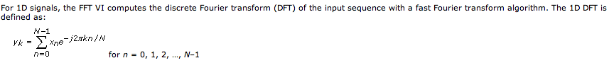
Read the detailed help file will give you a formula. If you want more details, open the block diagram and it performs an FFT of the input data and then uses a peak finding algorithm to interpolate the exact frequency of the three dominant bins.
Lynn
-
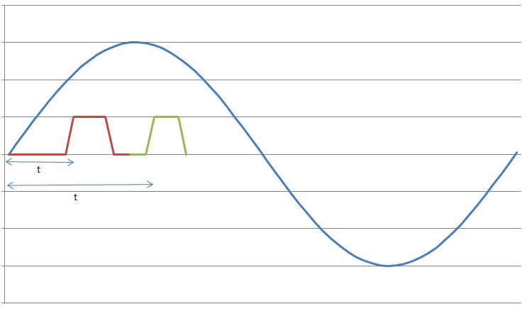
I have a sine wave of 50 Hz and a pulse of the signal on the same chart. The difference in phase between the two is between 0-90 degrees.
Now I need to calculate the time difference between (when the sinusoidal wave passes through zero volts) and (when the pulse increases). The frequency will remain about even for the two signals.
The request is for a three-phase generator. In simple terms, when the difference in time between the passage to zero of the sine wave and pulse increases increases, it means that the load on the generator has increased.
I am a novice user of LabView (version 9, 2009), maybe it's a very simple problem but I was pulling on my hair for the past few days and couldn't understand anything. Any help would be greatly appreciated. I use DAQ USB-6008 to measure these tensions and the impulse of the generator and a sensor
I have attached a jpg file (a graphic that I just did with excel to explain). The time 't' is what I'm trying to measure
See you soon
Zdzislaw
Awais.h,
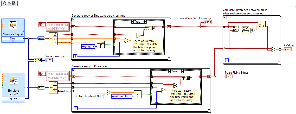
For problems of this kind I recommend start writing the granular steps you would take to manually fix this problem. You can't say LabVIEW (or any programming language) If you can't succinctly describe the solution to your problem.
The I want to address this problem is to:
- find all the zero crossing points and edges on the rise
- for every rising edge find the difference between the timestamp and previous passage by zero
Here is an implementation of this algorithm LabVIEW:
-
How to correct the difference of phase because without delay?
Hello
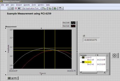
I use the DAQ card 6024E to acquire three sine waves of 50 Hz sampling rate of 20 kHz, sample to read: 2000Samples. I need to view and measure the difference in phase between the signals. However, I understand that there is without delay, leading to the release of phase measurement. Taken from the book of graphical programming LabVIEW, it is advisable to entry for common signal and display on the same graph. use graphic cursors to measure the timing of the track-to-track of tilt. Then apply timebase correction values can be applied to data from setting X 0 (initial time).
What I tried that I have attached in the printscreen. But I don't know how to include the other channel in the same graph to compare the signal. Can someone enlighten me please how to do this?
I'm using labVIEW 8.0.
Your help is greatly appreciated.
POH, (NTU student)
Hi, thanks for the advice so far... but I always failed to implement the VI of tbd.
Here's how I solved it. I tried to change the start time in the book cited, but no change for her, even though the gap is increased, there still no change the displayed waveform. timestamps there were used to check that there is a change in the offset of seizures.
The need to implement so just align vi available in the library will work with an accuracy of all 0.01degrees of the waveforms.
Well this problem solved!
See you soon!
POH

-
I have a 9174 OR compact DAQ with an NI 9234 and a NI 9269.
I am in a position two accelerometers with the NI 9234. I get forms of appropriate wave and RMS values, but I'm unable to measure a good phase.
I don't mean to measuing a phase difference! I can do that already, and this isn't a problem (and not really valuable information).
I'm looking to measure the phase for one (or all) provided waveforms. The phase of an accelerometer is important.
While I can read a measure of phase (I tried two ways), I was not able to find a way to get a reliable measure of phase. NI Calibration documentation says to use the "extract only your Information.vi", but it puts my phase in all directions. The waveform is rolling, and so each measurement is varied. Using a FFT block provides a more constant value, but it is varied same function where he thinks that the waveform is being in graphic form.
The NI 9234 is a Module IEPE without integrated analog trigger capabilities, so I'm a little confused on this one. Examples/thoughts?
Thank you
Billy
Hi Billy,
I don't know exactly what you're looking for, but there are a few screws designed for phase measurements.
You have the Sound and Vibration Toolkit? If so, Gain of one-shot, stage, & measure of distortion may be what you are looking for. The SVT Gain and Phase VI or Amplitude and Phase VI spectrum can do. Again, you can have not these although according to tool boxes that you have installed.
Hope this helps,
Chris G
-
Create log of three screws - sometimes the data are missing
Hello
I have three screws measure in parallel in a loop
Three results are saved permanently to the global network and also in a text file.
The berries-global has always all the data, but in the text file is missing some data.
I think it is because the file is locked to a vi, while the other vi wants to write its data.
What can I do here?
Something like writing data in a queue and an another vi reads the queue and writes the file?
Or y at - it something like a "checking if the file is in use" - property? Then I could wrap up the only unused before running writing?
Thank you
Yes, writing data to a queue is the perfect solution. Quick access to the sender, writes the author in his own pace and no missing data.
/Y
-
Site of the error of phase 2 for the VPN site
Dear all,
We have a VPN site to site with a partner, we need to access three different hosts on the network of partners. Phase 1 came but there is problem with the guests of the three phase 2 we can only connected with a host of others are not connected, and they all share the same settings.
Below is show access ip list matching packages shown but connection to host failed
With the crypto ipsec to see his I saw send error and I don't know what could be responsible.
Any body who could be wrong please help me to am exhausted.
access-list
10 permit ip host 4.2.3.1 4.2.6.22 (647594 matches)
20 permit ip host 4.2.3.14 4.2.6.64 (47794 matches)
30 permit ip host 41.2.3.37 41.2.6.76 (581720 matches)Crypto ipsec to show his
local ident (addr, mask, prot, port): (41.2.3.37/255.255.255.255/0/0)
Remote ident (addr, mask, prot, port): (4.2.6.76/255.255.255.255/0/0)
current_peer 4.2.6.24 port 500
LICENCE, flags is {origin_is_acl},
#pkts program: encrypt 0, #pkts: 0, #pkts digest: 0
#pkts decaps: 0, #pkts decrypt: 0, #pkts check: 0
compressed #pkts: 0, unzipped #pkts: 0
#pkts uncompressed: 0, #pkts compr. has failed: 0
#pkts not unpacked: 0, #pkts decompress failed: 0
Errors #send 198, #recv errors 0local crypto endpt. : 4.2.3.16, remote Start crypto. : 4.2.6.24
clearly, mtu 1500, path mtu 1500, mtu 1500 ip mtu IDB FastEthernet4 ip
current outbound SPI: 0x0 (0)
PFS (Y/N): N, Diffie-Hellman group: noSAS of the esp on arrival:
the arrival ah sas:
SAS of the CFP on arrival:
outgoing esp sas:
outgoing ah sas:
outgoing CFP sas:
local ident (addr, mask, prot, port): (4.2.3.14/255.255.255.255/0/0)
Remote ident (addr, mask, prot, port): (4.2.6.64/255.255.255.255/0/0)
current_peer 4.2.6.24 port 500
PERMITS, flags = {origin_is_acl, ipsec_sa_request_sent}
#pkts program: encrypt 0, #pkts: 0, #pkts digest: 0
#pkts decaps: 0, #pkts decrypt: 0, #pkts check: 0
compressed #pkts: 0, unzipped #pkts: 0
#pkts uncompressed: 0, #pkts compr. has failed: 0
#pkts not unpacked: 0, #pkts decompress failed: 0
Errors #send 508, #recv errors 0local crypto endpt. : 4.2.3.16, remote Start crypto. : 4.2.6.24
clearly, mtu 1500, path mtu 1500, mtu 1500 ip mtu IDB FastEthernet4 ip
current outbound SPI: 0x0 (0)
PFS (Y/N): N, Diffie-Hellman group: noSAS of the esp on arrival:
the arrival ah sas:
SAS of the CFP on arrival:
outgoing esp sas:
outgoing ah sas:
outgoing CFP sas:
Edit: can you put the configuration on both sides of the tunnel? Otherwise re - check once more the configs on both sides
-
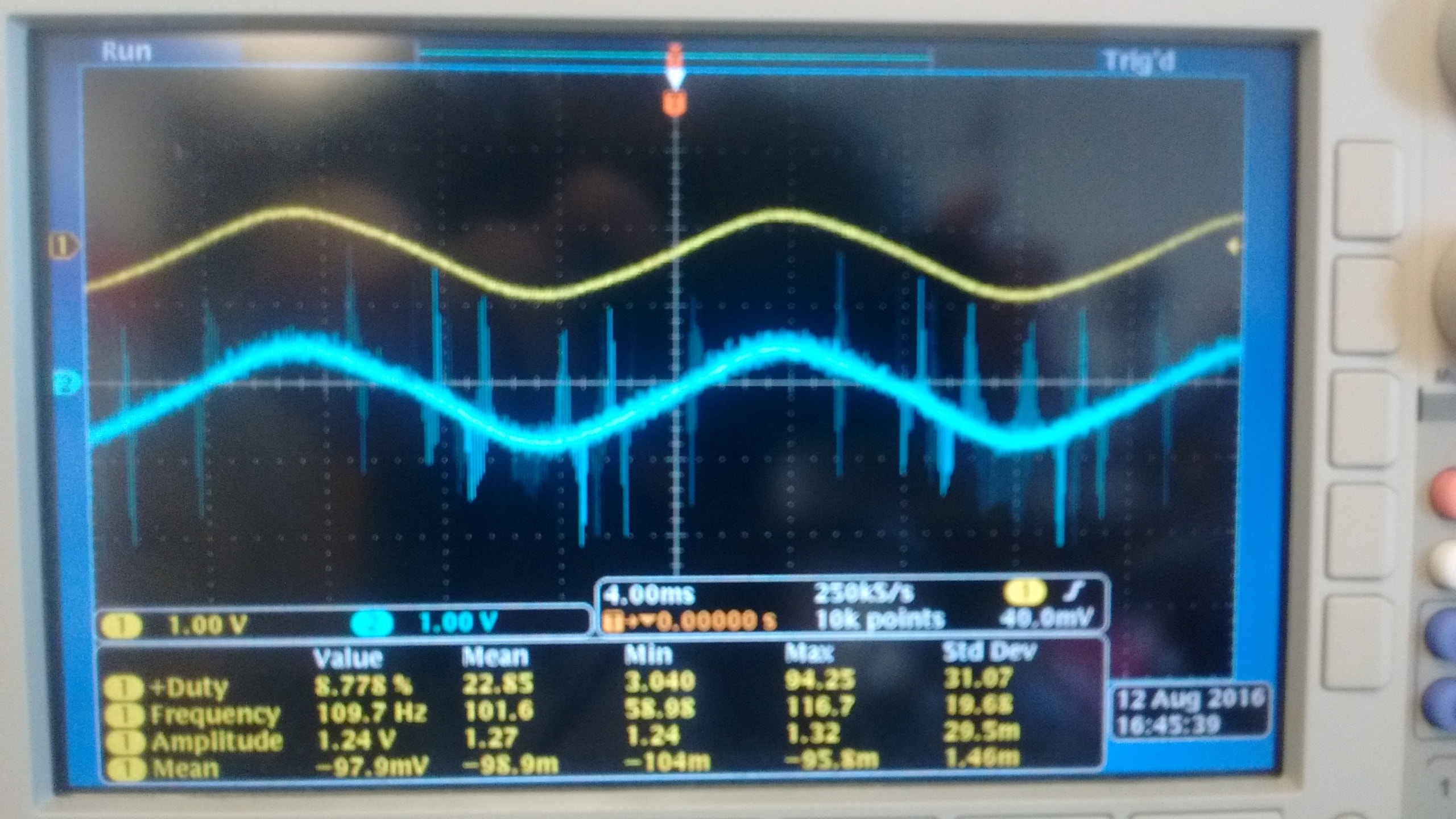
I currently use a NI 9215 module with BNC terminals to read the outputs of two different types of voltage sensors. Probe is a probe differential o-scope (Tektronix P5200A) which has a rejection of sound very good, while sensor B is a shunt isolated hall effect measurement using a LEM lv20-P and a custom PCB, which has a considerably lower noise rejection. Noise in the circuit to be measured is mainly the result of a H-bridge Inverter circuit that goes to 10 kHz. A picture of two sensors measuring the same signal displayed an o-scope is shown below with the sensor signal on top and B sensor on the bottom.
As you can see there is a lot of noise in the B sensor while sensor A is most often silent. When I connect then both of these signals to my NI 9215 I get the signals shown below (75 kHz sampling rate), sensor A appears in white and green B sensor (ignore the differences in scale, it's programmatically).
As you can see the noise level in the two now is comparably high. However if disconnect us the 9215 B, the signal from the probe sensor then replaces the image below:Although there are some present noise, the signal is much cleaner than before. The natural conclusion that I draw from this is that there is significant interference between the two signals. The same wiring is used for connecting to the 9215 as o-scope, and the two sensors use shielded twisted pair cables. This amount of crosstalk seems very high compared to the - 80dB listed in the specifications of the 9215. Any ideas what could be the cause, or how to fix it? Unfortunately, I am currently unable to afford a second sensor A.
1. by the impulses of the runt, I was meaning extremely short pulses on A sensor. If they are short enough, you will not see them unless you are looking for.
2. my concern is whether the switching noise is contaminant entering your power supply through the electric wiring. Of course, good feeds should filter this point, but it's just another thing to check.
3. the quick and dirty way would be to use a BNC T-connector to connect the oscilloscope and the ground in this way.
Suggestion of ferrite chokes on instrumentation Henrik is a good.
I understand that this type of inverter using the load (normally three-phase current motor alternative) to filter the frequency of bridge (10 kHz in your case) to the required frequency (normally 50 - 60 Hz). This means that high frequency currents go all the way to the motor, if they are not filtered by the cables first. You can not just screen the housing of the inverter, because the currents of high frequency down to load part of its operation. If you start testing things, you will all the way from the inverter to the load of the screen and will be impossible to Rodez to meet your instrumentation.
Standard WARNING: If you are tempted to connect directly to the UPS output and reduce until the input voltage range 9215: first of all, make sure that a qualified person has verified your wiring. Second place of fuses in all lines near where the tension is taken offshore. A UPS maybe a current loophole in the beach A 100 and you don't want that to the bottom of your wiring of instrumentation. Not directly relevant to your ad, but I feel that I specify.
Maybe you are looking for
-
Pavilion 15-n003tx: replacement card mother HP
I have a Hp Pavilion laptop which the warranty period has expired. A few days ago, he got shut down and never restarted. To the service center, I learned that the motherboard of the laptop is faulty and must be replaced. Can I get my motherboard repl
-
I need extensions for el Captain photo
In el Capitan Photo he repeats to me to add extensions, but I don't know what they are asking. I can't send anything from picture to Mail.
-
Problem installing disktop 800 wireless drivers for windows xp
Problem installing disktop 800 wireless drivers for windows xp
-
Top of page background desktop
HP has wallpapers for desktop HP with HP log on it? I tried searching in the site but no luck, I don't want to download wallpapers of another cause of sites that I'll probably download a virus, here I know its safe, but if an irritable HP can tell
-
Wmp300n - Windows 10 VERY SLOW INTERNET
I think that we need fresh drivers for this wireless adapter. Is that someone can help. Thank you