Time real ADC/DAC for SMPS by using Labview and USB
Hi all
I asked the Sales Department of this same question, so here's a two-pronged approach:
I am reserching a control algorithm for power switching, and so far, its performance simulations seem to be good. Now, the goal is to implement the circuit from the experimental data.
I've seen several NI USB DAQ boxes that seem to have the performance, I'm looking for (for example, the box USB-6211 a sampling rate and resolution I need).
The control algorithm uses the following mathematical functions: add/sub/mult/div/exhibitor and derivative/integral.
My question is this: is "strong enough" Labview take four-channel data 250Ksps, crunches the numbers in an equation and spits out the answer to an analogue on the channel, while time REAL? I'm looking for a rate of analog output of ~ 100 kHz.
Thank you for any suggestions you have!
-Rick
Hey,.
So if you were trying just to perform an input or output, then the box USB-6211 would certainly be able to treat it as the machine clock could manage the inputs/outputs, no software. However, what you are wanting to do, basically a feedback system, he will have to avoid (at least to a USB device) because you need to be able to specify Active which is the output. So, for this reason alone and the fact that you want out of 100 kHz, this device and the USB devices in general will be not an option any what software you use, LabVIEW or otherwise. On another note, you want to make sounds more like live update, not in real time, which is more on the jitter. Bottom line, for these kinds of requirements, you might need to move to an FPGA card, something like the NI PCIe-7841R would work. It's more expensive, but for your needs, FPGA will be the only option and it comes down to the latency of the bus, but also the response time of software. With FPGA, as shown in the first scheme of the following document, you basically close your software through hardware loop.
Basics of FPGA
http://www.NI.com/white-paper/6983/en
-Ryan S.
Tags: NI Software
Similar Questions
-
you want to create a new look for our website using Muse and move the hosting of GoDaddy for Business Catalyst. How can I publish my new Muse on exsiting URL design and change hosting? @@
Hi love,
You can publish your Business Catalyst, simply open your file of muse and select files-> publish.
Please refer to this tutorial:- publish your site with Adobe Web Hosting | Learn the Muse | Adobe TV
In addition, once your site is published, you can add your domain to your site hosted on BusinessCatalyst.
Please refer to this tutorial to add your domain name:- http://helpx.adobe.com/business-catalyst/using/change-site-domain.html
Hope this helps
Kind regards
Rohit Nair
-
In time real PXI-1031 does more work with labview. "Not enough disk space to perform the backup.
The labview real-time project was working until a few weeks ago and the only error that is displayed on the PXI is this error message.
"NEITHER Configuration Manager: not enough disk space for the backup" everything before that looks like it starts very well. Recently, I removed the hard drive and remove the 4 GB network log file because it seemed to me that a file of 4 GB on a fat32 file system was probably the cause of the problem. After that it the project worked when I tested it, but others in my lab said it was broken again the next day.
Any help would be greatly appreciated because I don't know all that equipment.
I found that I had "reset IP" set to "yes" in the bios that seemed to be causing my problem because I changed it to no and it seems to work perfectly now. Sorry that it took so much time to understand and I feel like a fool.
-
Using LabVIEW and LabVIEW 7.1 2010 on the same PC (Windows XP)
I have LabVIEW 7.1 on a Windows XP 32-bit PC, and we intend to move to LabVIEW 2010 soon. Many of our software uses traditional DAQ, DAQmx and DeviceNet. We have to use both versions of LabVIEW for awhile on the same PC. Is this possible at all?
I installed a trial version of 2010 and now I don't have DAQ and DeviceNet in LabVIEW 7.1. Any suggestions will be very useful.
Thank you, Nick
See this recent thread:
http://forums.NI.com/T5/LabVIEW/DAQmx-version-for-LV-8-2-1-and-2010/TD-p/1276594
Then maybe you can use different boot partitions or virtual machines.
Felix
-
Recognition of map to play using LabVIEW and a webcam
Hello
For our project in my school (2nd year of electronic engineering), we are a distributor of Blackjack robot. In the help of LabVIEW and a webcam we'd like to take a picture of the card he's going to face and then compare it to a database, we did prior to that the program knows which card it is.
So what we really want to do is
-scan the card he'll deal with (take a photo of him)
-compare with our database of predefined photos of all playing cards
-Once it has good info is obtained, channeling through our program so that we can count and whatnot with this card.
-He needs to recognize the value of the card, not the type (i.e. must know that it is a 4, not that it is a 4 diamond)
I have not found a good solution, again, can someone help us project? Any tips are appreciated with kindness

Kind regards
Vincent
-
Installation of the minimum runtime for the program using the driver USB of NI-VISA personal
I have a LabVIEW 2009 application that uses a driver for a USB device, created using the wizard of the Driver NI-VISA. What my minimum installation of runtime needed to understand when I move it on a non-development machine?
On my dev machine, I went to MAX and given my new camera USB one alias of VISA. I think I'll meet trouble if my deployment includes no MAX on TIME machine.
Right now, I guess the minimum is LabVIEW 2009 DURATION, NOR-DAQmx Configuration (including MAX) execution, duration of NI-VISA.
If not, is there a method that avoids having to configure an alias altogether? It would be nice to not not need NOR-DAQmx, I use not any material that my USB device with driver custom.
Thank you!
Not sure why you consider same installation DAQmx. You can install just MAX, the VISA duration and your harware MAX configuration. The installerallows of LabVIEW allows you to export the configuration, and then you select the option to import on the deployment computer. You will also need to include the installation of the inf file you created with the wizard.
-
Use wireless and USB at the same time on an OfficeJetPro 8500
I have a HP OfficeJetPro 8500 Wireless I want to use both wireless to other computers by using the USB connection to the office which is in the same room and the House. Is it possible to do both at the same time? The manual suggests that you connect using wireless or connect USB but says nothing about aid from both. Thank you
Hello
Yes, you can do both.
Install the USB with your desktop computer at the office.
Install wireless on other wireless devices. Your other devices should find the OJ Pro 8500 Wireless and connect. You should be asked the SSID and password on these devices.
It will depend also on the number of wireless devices can manage your router, so make sure that your router is capable.
-
Why is it only for letting me use black and white gray for colors?
Whenever I try to use another color such as blue, red, purple any color, will it just Gray, black, white... why?
Look in your menu under Image > Mode. Is is set to Grayscale? If so, choose a mode that supports color.
If this isn't the case, put some screenshots.
-
Choose and place using labview and or vision acquisition
Hello world
I'm doing a project studying on Vision guided pick and place of a robot (abb) industrial. I would like to know the steps involved in the creation of the block.
I locate the object, move his webcam cooordinates. Then made a pattern match, and would send the cooordinates to the microcontroller. then from microcontroller for control of robot... then the industrial robot should choose the object and place it in a predefined area...
I would be extremely grateful if you guys can help me because I am new to LabView.
Thank you
Pradeep.M
What you describe is quite complex, but here are a few tips. The key is to establish a correlation between the coordinate system of the robot to the coordinate system of the camera. I guess that the camera is statically located above the pick-up area? I move the robot at each corner of the frame to its choice position vertically and note the position of the robot at these locations. These 4 points in space will be correlated to X, coordinates of pixels in the camera image. Basically, you need to write a sub - VI with entries being pixel X and is coordinated and coordinates output being the robot.
Writing a test application saying the robot to get pixel location to any X, Y in the framework to test your Subvi. If this does not work, then you need to set up a correspondence to the model. You probably want to do a geometric pattern match. Take a look at this example: http://zone.ni.com/devzone/cda/epd/p/id/5555
You will need your pattern match algorithm to return both the coordinates for your robot, and the orientation of the tool needed for good pick up the object (if the pick-and-place robot tool requires to be in a specific direction). If it's basically up to you will convert the object X, Y and rotation angle in the framework that you receive correspondence from model to any coordinate system, the robot uses.
The placement algorithm could be simply an adjustment of orientation to the object being investment and then investment positions could be an array of coordinates of robot which you browse after each pick.
Be sure to implement security mechanisms in your algorithms so that the robot can never go somewhere outside of a safe range of coordinates.
-
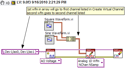
Using Labview and PXI-4461, how can I AO0 output Signal Square and AO1 output waveform
I am using PXI-4461 and Labview, boredom, generating 2 signals simultaneously.
How can I get AO0 out square and exit AO1 SignWave?
Help, please. (The example Code would be nice)
Thank you.
Create two signals and make a table with them. Use DAQmx Create Virtual Channel to create two channels. First waveform will be sent to the first string, second waveform on the second channel.
I understand not all as calendar, clock frequency, amplitude, trigger and other parameters. You can add these things. This is just a basic example.
-
Need drivers for Pavilion 17Z-e100 - network and usb Win7
I need drivers to support Win7 on Pavilion 17Z-e100. Ethernet controller, network, PCI Devie, SM Bus controller, & usb controller.
Hello:
These drivers should work for you...
First, install the amd chipset driver and restart. You want the third file listed on the webpage (49.7 MB).
http://support.AMD.com/en-us/download/chipset?OS=Windows 7-64
Then, install the beta amd catalyst driver and restart.
http://support.AMD.com/en-us/KB-articles/pages/latest-catalyst-Windows-Beta.aspx
Audio: Accept the agreement, download and install the driver for the second on the list. "
Ethernet: Download and install the driver for the second on the list.
USB 3.0: Install both.
Card reader:
3D Driveguard:
Webcam:
For the network controller, proceed like this...
In order to obtain the driver for the wireless card, do like this...
Go to Device Manager and click on the network controller needing drivers.
Then click on the Details tab at the top of the control of the network window.
Now, you see a drop-down list of property and it is set by default to the Description of the unit.
Drop down on it and select the second item in the list (Hardware ID).
After the first string of characters that start with PCI\VEN
-
Problem using labview and GPIB
Hi guys,.
Finally got recognized my tool GPIB in labview, which is nice. I created the block (attached you can see you diagram) but it works like 20 sec. I press run continious and I can change the values in direct mode, as I hear it. But then after 10 seconds, it appears the error that is in the screen and only works again if I reboot the function generator.
The model is Tektronix AFG3102.
Concerning
-
reading photoplethysmograph waveform with serial port on PC using Labview
Hello world
I'm gaining time real Photoplethysmography waveform of serial port using Labview.I have managed to acquire data from serial port by using the following features:
-Baud rate: 38400
-data bits: 8
-stopbit: 1
-No parity bit
-Time delay before reading the serial port: 10 ms (according to what was written in the manual that every 10 ms there is a frame in serial port)
After the reading string will be converted to byte array to be able to extract the bytes associated with waveform (1 & 2 bytes in a frame) even for SOP2 (6 & 7)
(what is read in serial port is in decimal and must be converted to hexadecimal based on what made the software of prodeuct for some result.that in the waveform properties, I chose the hexadecimal representation)
Then, as mentioned in the manual, I associate these two values to draw the waveform.
Although I used the filter band digital waveform of pulse but not significant pass that was seen (cutofffrequeny:10 high low cut-off frequency: 0.5).
I have attached my program and result in front of Panel and manual for the sensor. The result is still far from what is supposed to be. I was wondering if you could help me and let me know your opinion on the program and the protocol used. I have to get the result as soon as possible. Please let me know if you need more information.
Kind regards
-
Automing instruments LabVIEW without using specific and coding drivers for each instrument?
Hello
I'm new to programming in labVIEW, but I had a few questions about its use in automation and remote controlling several instruments.
It is an ideal software for automation of various instruments remote control/test. Assuming that I have several different companies spectrum analyzers, I understand that labVIEW drivers of instruments or special VI who would control these instruments. But if I wanted that all these spectrum analyzers to say, to display on another computer using the remote control, but I wanted to use the same program for effeciency, is it possible to do so universally for all instruments using labVIEW? Or do I have to adapt this program for each instrument to instrument drivers cause?
If labVIEW can do that, is - anyone had good success for such scenarios in other programming languages?
Thanks in advance for your help.
Look for the Abstraction Layer material (that you can implement with LabVIEW, even if it's a slightly advanced topic).
The idea of having a specific Test and be able to enforce it against different Instruments, decided at run time, is the kind of situation that LabVIEW and use of HALs was designed to facilitate.
The concept is to 'Levels of Abstraction'. When you create a test, you can design it for an abstract Framistan, since all the Framistans are supposed to be able to measure Vorbels in the range of 0 to 100, so you just plug a generator of Vorbel to generate Vorbels in a certain sequence of Test (linear, random, quickly, slowly, pulsatile, continuous, you decide), measure your Abstract Framistan records readings and compare with the results you expect write the results in a nice report.
Of course, Framistat of OR uses Ethernet as the means of communication, while HP uses a serial port (depending on the model, series settings can change) and uses of the Intel one. DLL to communicate with the low-level API. So you also need to develop, for each specific instrument, an "interface" between its API and the Framistan abstract (not everyone uses Vorbels as the input unit, for example).
So the good news is that it can be done, the bad news is that one of the best ways of handling this type of question on the programming is to use OOP (OOP). A number of languages (LabVIEW, C++, JAVA) support OOP, but LabVIEW might have the advantage when it comes to interact with the material.
I you are looking for Hardware Abstraction Layer? Add LabVIEW to the search query and you should find some nice presentations by Elijah Kerry...
Bob Schor
-
help the guitar hero automated using labview
Hi, Im working on my final project for a class e and Im making a guitar hero automated using labVIEW and vision builder. I already have all the buttons and the strum bar, but I need help with the whammy bar. My problem is that it should only work on the notes which take more time with a single click, I think I should add some time delay (or something like that) so if the camera sees the note more times the amount of time its will send a signal to the solenoid to continue to press the whammy in intermittent form bar (I think I need a square to wave this) part).
I'd really appreciate if someone can help me or show me an example implementation of the part.
Here is a video of a similar project without the whammy bar
Edit: Im using a NOR-cDAQ 9472 module for output on a digital OR cDAQ 9171 chasis USB
Thank you
Javier Morales
Dear Javier,
It sounds like a cool project work.
Why not try wiring of the output of the shared in a shift register variable to retain the previous values and compare the old with the new value using a door and. You can connect to a wait function in your loop and wire abour 100ms, normal human reaction time, while is the button held for two cycles this triggers your whammy bar.
I hope this helps.
Kind regards
Maybe you are looking for
-
I'm looking for advise on the viability of the USB3.0 added to my desktop PC. It's a HPE-475UK - two years. It seems to be an obvious step due to the benefits of speed and future accessories. However I seem to be unable to find information that suppo
-
How to get the windows on lenovo thinkpad x 201 product key
Hi allNeed help please, I used to computer laptop lenovo x 201, but the windows product key been removed sad Smiley. also the warranty has ended, so how can I get the product key? Help, please [Title edited for clarification]
-
I recently reinstalled Windows XP Professional with SP2 and cannot access all internet. I have a wireless home network setup and it works but the R52 connects with him help thank you
-
Blue-Ray to recognize my Vista PC to PC streaming
I would like to know how to create a password for my computer so that the Blue-Ray will recognize my PC and I can start to use a shared folder and a PC streaming Thank you
-
Flow on the client machine connected RAS VPN multicast
Hi all I got a requirment, it is the flow of Muliticast need access via RAS VPN Scanario: I have ASA 5540 peripheral, configured profile RAS and user that connects to the ASA device to the standard access via VPN server. We have now posted on the Web