Timed software a generation of impulses - USB-6009
Hello.
I searched for a reliable way to produce a pulse point by point with the USB-6009. My question is whether or not it is possible to produce such a signal without hardware timing or a counter as the USB-6009 supports neither. Is the closest I've come to produce a square with a very low duty cycle wave. However, what I would ideally look for is the ability to produce a single pulse inside a loop which I can go once per minute or more. Also, I would like to know what are the parameters I would be sacrificing to produce a pulse in this way.
I also have access to a function generator and as it seems quite difficult I will be probably triggering just its pulse function in the same way, but I'd like to explore this obstacle before moving on.
Thank you
Travis.
20 ms can enter the region where you will begin to see significant amounts of timing jitter. You really need to write your program and make some careful measurements - over a long period of time - to see how much of a problem you will have. Actual performance will depend on a lot of details: the operating system, other software process running in the background, and how the LV program is implemented. You must reduce as much as possible, everything else on the computer: no network, no antivirus, no Bluetooth or WiFi connection and so on...
Lynn
Tags: NI Software
Similar Questions
-
generation of signals USB-6009
Hello!!
Can someone suggest me how to generate a pulse of 3V/0V to output pin (a01) to change the transistor...
requirement is: 1ms - 3V and 400ms-0V permanently...
With the help of NOR-USB-6009
Thanks in advance!
The short answer is that you cannot do with the USB-6009 case. Outputs analog device are timed software and 1 ms pulse is too fast for the outputs timed software. According to the computer, OS and other software activities and perhaps the phase of the Moon, you can only expect rates to update AO 100 Hz to a few hundred Hz and there may be considrable timing jitter at these rates.
You must obtain a DAQ device with hardware timed AO.
Lynn
-
USB-6009 software simultaneous timed output analog
Ladies and gentlemen,
I worked on a LabVIEW interface to a potentiostat I designed and built. I'm not very experienced with LabVIEW, but do they have experience with a variety of other languages (I had originally intend to use an FPGA for this, but he has been asked to write a LabVIEW VI first) programming.
The goal:
I want to output a voltage (initially consisting of ramps) signal and measure the voltage with an operational amplifier configured as an ammeter of feedback (using resistance feedback and voltage value to calculate current) connected to an electrochemical cell. The resistance of feedback is selected by using an automatic selection function (although I wrote a version prior to manual control) as TTL values using the DAQ Assistant to select relevant MUX channel outputs. I then try to save the data in a spreadsheet.
The problem:
I use an acquisition of data USB-6009, and I know that there is a hardware clock. Read all about him seemed obvious, the best way to the waveform of the output voltage used DAQmx package to define a function of writing in a loop that is clocked by the software. The problem I have is that I can't synchronize the output to the input with reliability and I have also some errors related to resources DAQ being reserved (error 50103). I think the way to solve this would be to convert every equivalent DAQmx DAQ Assistant and try to group their execution - this is where I fall. I tried to write a simple VI who shared a loop clocked by the software to read and write but had problems related to the value of min HAVE (error 200077).
General issues:
How I begin the process of read/write (with a Boolean switch) is very weak and doesn't feel not robust. Ideally, I would like to some form of indicator to warn the user when the read/write process is running and when it ended.
My error handling is terrible, but I find no big thing to read about the basics.
I use only a sequence of no and I think I should have more.
Once I hit the beginning, VI requires the file name for the worksheet - at first, I was afraid that data would be entered correctly, but I think it's okay because the file is generated and then changed. It would be better if the user asked for the name of the file once completed the data collection.
Any suggestion or help would be greatly appreciated. Thank you in advance.
Sincere greetings,
Julius
The hardware supports timed 6009 entry analog. Even with the 1Samp mode, your code could be simplified with a single task and several channels (dev1\ai0:1). Then use Nchan 1Samp.
-
Hello
I use a card DAQ USB-6009 to read the signal from 3 channels. at the same time, I want to read a TTL trigger and genearte a TTL trigger or a waveform square with a delay of 4 seconds.
I'm reading the trigger and then write with "wait" function in my loop. but I find that there is a bug with the writing of the matrix. I can read the writing the trigger with single channel, but not with multiple channels.
Here's the EIS. Please help me with the file of multiple channels to see why it does not work.
You have designed your application correctly; I would recommend going through the following steps:
-
Digital and analog inputs simultaneously - NI USB-6009 and NI USB-6212 - ANSI C
Hello
I'm reading at all times and at the same time analog and digital inputs. Digital and analog samples must be sampled at the same clock and acquisition should be started (triggered?) at the same time (I don't want, after some time, analog reception more digital samples - the opposite is also true).
I found an example (in C source code) "National Instruments\NI-DAQ\Examples\DAQmx ANSI C\Synchronization\Multi-Function\ContAI-Read dig Chan" and tried to run with two USB cards: NI USB-6009 and NI USB-6212. Unfortunately, the two results by mistake, as described below:
DAQmx error: the requested value is not supported for this property value.
Property: DAQmx_SampTimingType
You asked: DAQmx_Val_SampClk
You can select: DAQmx_Val_OnDemandTask name: _unnamedTask<1>
State code:-200077
End of the program, press the Enter key to exit-Is it possible sync analog and digital acquisition in the paintings?
-If so, how?
Thank you
Hello tcbusatta,
Two of these modules, USB = 6008 and USB-6212, support only timed software inputs and digital outputs. This means that you cannot define material timing (like finished sampling or continuous) for these modules. Digital lines can be retrieved or written once to each call DAQmx read.
This means that you will not be able to get any type of synchronization tight between the analogue and digital channels. You will need a Board such as the NI USB-6341 in order to synchronize the AI and DI closely.
-
Why is the selection of the mode disabled in max for NIDAQ-USB-6009?
I try to use NOR-USB-6009 AO to generate the sinusoidal signal.
(1) I want to use MAX, but the selection of the mode and frequency are all disabled in the "Analog output" section
(2) I find a VB example to generate the sine wave, but I received an error message.
I want to know if the OR-6009 function support limited or not...?
The attachment includes the screenshot.
Thank you very much!
Kevin
Kevin,
Yes. Timed software means that the appliance has no internal clock or the buffer. You call the AO write with data point. Then you call AO write later with another data point. Repeat until cooked. This means that the maximum rate of update of the AO is approximately 100 hertz or a little faster. It also means that there is a lot of jitter of synchronization due to latencies of the OS at speeds like that.
Think about AO on the USB-6009 case as a parameter Variant sometimes of continuous tension for your system.
Lynn
-
How to synchronize clocks on USB-6009 and USB-6343
Hello
Can anyone provide an example on how to synchronize clocks on USB-6009 and USB 6343?
I checked the example screws, but it shows that we must use 2 counters, one as the clock of the source and the other as a trigger. But only 1 CLK 6009.
I read the user manual and it is mentioned to use (AI/start-trigger) in order to use PFI0 as source.i am somehow confused about how to achieve this.
Furthermore, what would be the physical connections?
Thank you
LV_Enthu
Unfortunately, you won't be able to completely synchronize your devices USB-6009 and USB-6343. As you have seen, the 6009 has only a meter on board.
You can certainly use PFI0 as an input to start your tasks at the same time digital release. However, the 6009 is a strictly timed by the software. There is no way to import an external sample clock.
-
Acquiring bipolar signals NI DAQ USB 6009
Hello
The NI DAQ USB 6009 case is capable of acquiring biploar waveform? I have a signal generator that provides a 0.5V wave triangular amplitude in the NI DAQ USB 6009. The NOR-DAQ is connected to LABView and acquire signals using the LabVIEW express vi. The waveform that appears is unipolar. Terminal configuration is set to differential. Is the waveform which is seen. Thank you. Mary
Hi Tupaj,
See a voltage floating as this can sometimes be the result of a measure badly grounded. It would be useful, like Dennis, to know how you have this wired up. Please take a look at this guide to make sure that the device is properly connected to Earth:
Field wiring and analog noise - http://www.ni.com/white-paper/3344/en
In addition, information about the configuration of your software are also important. Here's an example of how implementing a fundamental mission of analog input for your 6009:
Video installation instructions - http://www.ni.com/swf/devzone/ai/
The example Finder has also several screws that already do it for you. If you work in 2012 before LabVIEW, look for Acq Cont & chart voltage-Int of the Clk.vi in the Finder of the example. LabVIEW 2012 will have a similar named VI voltage - Software-Timed Input.vi.
Kind regards
-
Hello
I have a USB - 6009 DAQmx. I want to measure an analog input with the highest possible sample rate (48 kHz). At the same time, I need an analog output in voltage from 0 to 5 Volts, lets say 2 minutes of the ramp. Both of these tasks require no synchronization of relatives. With respect to the specification, the highest rate of the AO is 150 Hz. It's ok for my application.
So far I use the internal clock of the device, and the OD does not work with a timing of software. Is it possible of ramping regardless the voltage output and at the same time reading analog input? If not, is there a work around for this device?
Thanks for the tips!
Kind regards
HI Blook,
your VI test seems ok. Of course, given that the AO is in sync SW and you run it on a Windows platform may be you will see some jitter on the output. But you said, you don t need a thight synchronization, so it shouldn´t be question.
For what concerns the way in which LV manages data acquired from a multiplexed DAQ card, that should be kept in mind
that the timestamp of the waveform is generated from the driver on the PC and not directly on the map. This means that even if the sample of both channels are acquired in two different
moments (like you supposed to separate by the time of the ADC) this will be transparent to the SW and they will be considered granted exactly at the same time.
National Isntrumetns offers also simultaneous of sampled acquisition card (and not multiplexed) to overcome this problem.
Best regards
André
-
Hi all
I am a new user of LabView with only a CLAD certification so please forgive my ignorance on the subject at hand. I try to use a DHT 11 temperature sensor and moisture (Backgrounder: http://www.micro4you.com/files/sensor/DHT11.pdf ) with a casing NI USB-6008. I not had a bit of luck to find information about this combination of data collection and began to wonder is it still possible.
I don't know that DHT output digital signal sensor and it is usually used with a card Arduino but I need to use it with my DAQ.
- Can someone give me a general run down on whether or not it is possible?
- If so, what will do to allow the DAQ and sensor to communicate?
- And if it is not possible, any information on why that is and suggestions on what I can do to integrate data on the temperature in my LabView code using the USB-6009 case?
I apologize for the size of my question, I'm looking for the General knowledge on the subject so I bridgehead to attack my problem at hand.
Thank you
Sleepar
Sleepar,
You will not be able to use this sensor with the box USB-6008. Although it is rather badly written the specifications document, it is clear that the timetable is faster than you can achieve with timed entrances and exits of the USB-6008 mcuh digital software. With the USB-6008 housing you must think in terms of tens of "timing" minimum milliseconds on digital lines and allow considerable jitter at these rates. Anythign with microsecond timing is out of the question.
Probably the best way to get data on a USB-6008 temperature is to use a temperature sensor semiconductor as a LM35 and an entry for analog data acquisition.
If you need to use DHT 11, you will need some external circuits to capture the five bytes of data and present it in a format that the USB-6008 case could handle.
Lynn
-
Reduce the period of sampling of the digital inputs of NOR-USB-6009
Hello
I need to read a line of digital input in the NI USB-6009 using NOR Express 2013 Signal box. I selected 1 sample (upon request) as acquisition mode. I need to define a smaller sampling period as 1 MS, but it gives error too short sampling period: "the current sampling period is too short. Please specify a longer sampling period. ».
I do not understand the reason for it and a way to slove this.Any help would be greatly appreciated!
Thank you!!
The 6009 doesn't have a clock that you can set for a sampling period. According to the specifications, the digital I/o is software programmed - sample on request you use now. I'm not at all familiar with SignalExpress but I don't think that you can find near a reliable khz sampling frequency on Windows or any other os non-deterministic.
-
Synchronization features 2 usb-6009 - please help
Hello
I'm trying to simultaneously capture data from 2 devices usb-6009. I've implemented the two Renault as follows.
1. using a function generator, generate a sine wave, which is slower and not a multiple of the sampling notes (48 kHz) and apply it on the odd numbered tracks.
2. connect the pairs of channels on the ground.
3. connect the PFI0 to a digital output of one of the Renault.
4. implement each DAQ sample faster (48 kHz) as possible and trigger off the coast of PFI0 entry.
5 generate the shutter of digital output - software write to 'Dev1/port0.
6. read samples that result and determine the difference between each of the odd channels between the Renault in a given set sample.
My results are not as expected. Use Excel to plot the data, I see that the Renault 2 data are staggered on each set of sampling.
I checked on the scope that the trigger works and that both got triggered. I think that the configuration above is not complete and I think I need to
Configure the two Renault to share the same clock source, but I don't know how to set up 2 Renault to share the same clock. My questions are
(1) exceeds my setup ok?
(2) If you need to configure 2 Renault share the same clock, how to put in place?
(3) is it possible sync 2 devices usb-6009?
Thank you
Tuan
Your above configuration seems correct.
The method that you use to synchronize two devices is the best you can get. The PFI line can only read in a trigger or a counter of entry. You cannot use to import a sample clock. Each 6009 must use its own on-board clock.
Typically, if you really want to sinchronize both acquisitions you must share a sampling and a trigger to start clock. Here, we are only able to share a departure with the PFI line trigger (such as material prevents you from sharing the clock) and let the individual clocks govern the actual acquisition is simply not possible really to synchronize two 6009 s and you're doing the best you can.
Corn
-
Hello
I'm trying to use a box NI USB-6009 to acquire a low frequency signal (~ 1-2 Hz). I ran into the problem that the hardware supports only with a levy 'On Demand', so I can't set the number of samples, I want or the frequency with DAQmx features in LabVIEW. Because timing is essential to the functioning of my VI, I must be able to know what is the sampling frequency. What is the best way to determine this? A screenshot of one of the sections of my VI where I use DAQmx is attached. You can see that I'm really the time between each loop itneration, I read a sample by loop. Is there a better way to take a series of samples?
Kind regards
Steve
Fantastic!
I had used normally the method you described, but has encountered an error in MAX telling me that I could not choose the option to "samples continues." However, now it works. Don't know what changed, but in may cases, thank you.

Kind regards
Steve
-
Device driver in Linux and ready to compile application user for USB-6009
Hello
I intend to use the acquisition card to USB-6009 data under Linux platform. To do this, I need driver linux for acquisition card data USB-6009 and some read-compilation-and-program to use "user application" which can take samples of the card, to implement some buffering or write to the file. It would be beneficial if I could also get sample code to generate a sinusoidal low frequency signal, using the D-to-A converter available on the Board of Directors.
Also I need installation instructions for the NOR-DAQ software under standard linux environment.
Thank you for your quick and detailed response,
Adeel Malik,
Research engineer,
Institute of telecommunications research,
Mawson Lakes Boulevard,
Mawson Lakes,
South Australia, 5095,.
Australia
Mobile: + 61 0404 030 071
E-mail: [email protected]
Hello Adeel,
You will need to install the libstdc ++. so.5 Library. A Google search has a few useful discussions that give more information on the procedure to follow if you are not sure:
Let me know if you have installation problems - you can also try to contact redhat support if you are having problems. If you have problems, please post so we can document the troubleshooting procedure to help all customers who may experience this problem in the future. Thanks for posting!
-John
-
Hello guys,.
I am trying to create a simple VI to generate two outputs analog square with USB-6009. Each output supplies a LED and it is necessary that single LED shines at the time - so when Out0 is active, Out1 is zero and the other way around.
To get started, I created a VI in which the goods are made manually by Boolean and it works fine (square v1.vi of signal).
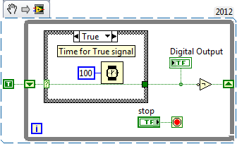
But I need the output to switch automatically after the amount of time given (I needn't of high frequencies, at about 1 Hz). To do this, I changed "square wave v1.vi" in "square wave v2.vi" and set the Structures of the case in an another While loop which would be timed by the wait function (ms). The idea was that the loop internal would turn the output rate of frequency while the outer loop would ensure a continued implementation of the programme. But the reality is very different and my low level of competence (this is my first VI) let me down. Could you please help me out of this? I appreciate all the advice.
To summarize: The VI must be continuously running program that generates two dependent signals with adjustable amplitude and opposite phases (Out0, when active, Out1 is zero and vice versa.). Signals must be switched automatically to the given frequency.
Here's a simple flip-flop - while time the loop runs, the Boolean line connected to the digital output passes from true to False to True... with the schedule determined by the time you put in waiting for him (note that you can have regardless of the different times for the true = on and False = off case). Of course, the life of signal (represented by 'Digital output') 'inside' this loop - you have to put the 1 point 1Line DAQmx VI write digital Boolean inside the loop, or find a way (for example, a queue) to get the data between the inside and outside.
Maybe you are looking for
-
How to manually backup and restore iphone content (texts, contacts, data apps) and apps?
How to manually backup and restore iphone content (texts, contacts, data apps) and apps?
-
Accounts iCloud duplicate not appearing in the Contacts on my Mac and I only have an iCloud account.
Accounts iCloud duplicate not appearing in the Contacts on my Mac and I only have an iCloud account. That's why I duplicate contacts. I went though the routine was suggested to merge duplicates, but it never finds any merger of duplicates. This probl
-
What does "...". managed to install with error Code 1073 Win32 error"mean?
The message appeared when you try to install a product registered and paid for a link in my email. the message says "the specified service already exists. previously, I have a trial version of the product, but it has expired. This is why I bought
-
Cannot install the Client VPN Cisco due error 1722
Dear, I went to istall the Cisco VPN Client SW. But my laptoop installation finished with error 1722. Here is the log file fagment: MSI (s) (74:B0) [12:07:23:006]: product: Cisco Systems VPN Client 5.0.07.0440 - error 1722. There is a problem with th
-
Hello Experts,Merry Christmas!(1) we decided to implement ASM for the stand-alone database to data files about 170. (DR configured)(2) decided to install the new RAC ENV on Redhat Linux 6.6 (DB version: 11.2.0.3)(1) I'm not good ASM for stand-alone d