timestamp of the cRIO
Hi all
I have problems with formatting timestamp on my cRIO.
I saw in MAX cRIO does not support the DST, I guess that why I get difference 1 h between the timestamp and the value of string formatted, right?
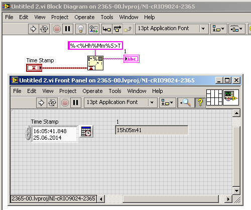
What can I do to get the channels match the timestamp display?
See you soon
Tags: NI Software
Similar Questions
-
cRIO-9074 ethercat with a switch/hub between the cRIO and slaves
Hi, I have a cRIO9074 I'll use 7 JVL EtherCat Mac800 motor control. Engines are fairly spaced, so I use a switch of CU2005 EtherCat Beckhoff 5 ports between the readers and the cRIO with 2 motors in series on three legs and a motor on a port by itself. My problem is that labview will not find all engines unless one of the ports on the switch motor is plugged, or a line of engine is connected directly to the port ethercat cRIO. He has no problem see two engines on the same line, it just will not see one of them if more than one line of motor is connected to the switch ethercat.
Thus, HALP!
-
9033 OR & NI 9870 - series recording parameters do not restart the cRIO.
Hello
I have a cRIO OR 9033 with two RS232 9870 cards. The two cards series and their ports do not appear when I turn on the cRIO. When I run my executable in real time, once it crashes, saying: he cannot find the ports I ask. After that it crashes, the channels appear in MAX and VISA resource controls, and when I run the program a second time, it works very well. Why does this happen? Is it possible that I can have the save of the series, so I don't need to have the program crash whenever the cRIO starts?
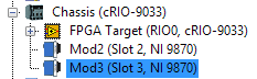
I run my program in hybrid mode. I Interface FPGA and including two maps cRIO outside the FPGA target, like this:
I tried the cancellation of the deployment and the deployment of all, but it does not help. It blocks the first time regardless if I execute the suite of LabVIEW Development or if I deploy it as an RT executable and run at startup.
Here are some pictures of what is happening:
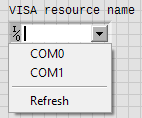
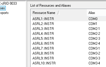
10-port VISA should be available. The two on the chassis and four for each card to 9870.
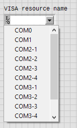
When I start first cRIO, only the ports of two chassis looks for selection in a control channel VISA:
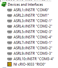
And the channels do not arise to the MAX:
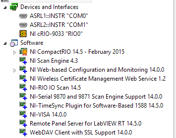
Showing also currently installed software.
When I go to the settings of NI-VISA 14.0.0 page I see this:
Channels appear here, but nowhere else.
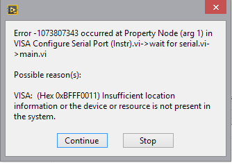
When I try to run my program, I get this error:
And after the error, the channels appear in LabVIEW and MAX!
Series settings will remain as long as I leave the cRIO powered. If I disable, settings series pannals and I need run my program once only it crash before I can use the serial ports.
I would really like for these settings apply automatically without having it fail the first time.
Any suggestions?
I also run hybrid FPGA on cRIO with cards 9870 and 9871 under the scanning engine you are. I also noticed behaviour buggy when accessing the COM ports - for example, if the cRIO running the executable version of his program and you interrupt it to run the same program in interactive mode, often, you receive the error message "missing resources VISA." So what I do is restart the cRIO with the disabled startup application.
I honestly would not bother to configure anything through MAX when it comes to your cRIO. You configure port configuration programmatically. In the process of initialization of your program, open your bitfile, run it, wait, a few seconds to have everything settle, make a VISA "find resources" and confirm all your ports appear, then use the VISA to configure and open the port by program. This way worked for me.
-
I have a cRIO-9075 serving piece of alternative/backup for one of our production test systems. I was about to try a new code on this backup, but I can't connect to it. I searched in MAX and tried to ping to the IP address that it should be, but I get no response. It has been configured with a static IP address so it would be ready to be deployed if necessary.
Is there anyway that I can get back to the default IP address so I can connect to it?
Take a look at page 17 of the user of 9075 Manual: http://www.ni.com/pdf/manuals/375650b.pdf
To reset the IP address of the 9075 you will need to walk through the following steps:
1 press and hold to reset for 5 seconds, then release. The status light
comes on, then starts to blink three times every few seconds. The
chassis is now in safe mode with the release of the compatible serial port.
You can use a serial port terminal to read the IP address of the
controller. If you want the controller to a new DHCP protocol
connection, go to step 2.2 press and hold to reset for 5 seconds, then release. The status light
Repeat the same behavior. The cRIO-9075/9076 trying to establish
a new connection to DHCP. If he fails, he attributes to a link-local
IP address. If the DHCP connection is effective and appropriate for
your application, go to step 4.3. configure the IP address and other network settings in MAX.
4. press and release the Reset button to restart the chassis.
The following documents will also be useful.
Why don't my CompactRIO or Single-Board RIO controller is displayed in Measurement & Automation Explorer (MAX)? - http://digital.ni.com/public.nsf/allkb/ABE4BC247E8AC9BC8625734E005CAB42?OpenDocument
Connection to a target LabVIEW Real - Time (RT) directly with a cable crossed - http://digital.ni.com/public.nsf/allkb/72AE8CADA1AF075686256A16005D55B1
-
Why my sample rate does not match the output of timestamps in the waveform?
Hello
I run a simple application to read the data of two pressure sensors output signals 0 - 5V to a NI9215 module, and one connected to the 9237 module load cell. They are housed in the 9172 chassis.
I am new to DAQ and labview, and I find it difficult to reconcile the sampling frequency that I put in the sample clock and the apparent rate data (according to the timestamps in the waveform that I output to a text file). For example, if I ask 100 Hz rate (and 10 samples to read), the data appear to sample at 1612,9 Hz. If I ask the sampling frequency of 1000 Hz, outgoing data is 1612,9 Hz to 20 kHz, the data came out to 25 kHz.
Can someone tell me to trust the timestamps given in the waveform that is written in the text file, and if there is a way to check this? If this timestamp is correct, how can I force the application of sample data at the requested speed?
As a secondary issue, in my attached VI, you can see that I have an attached to an array of construction shift register. I can't understand how to initialize the array outside of the loop as it clears the table before the next time I run the program. Any advice?
My VI is attached.
Thank you
Claire.
Hi Marc, thanks for the quick response and the right explanation. It's all much more clear now.
Have a great weekend,
Claire.
-
All,
I have a cRIO-9068 I try to use the scan mode for. I have intalled all the latest drivers and software as explained. However, when I put my chassis to scan mode, then select deployment all, I get this error on my chassis and all my modules:
"The current module settings require a NI Scan Engine support on the controller. You can use Measurement & Automation Explorer (MAX) to install a software package recommended NOR-Rio with NI Scan Engine support on the controller. If you installed LabVIEW FPGA, you can use this module with LabVIEW FPGA by adding an element of FPGA target under the chassis and drag and drop the module on the FPGA target element. »
Everyone knows this or know why labVIEW does not recognize that the software is installed on my cRIO or is it not installed correctly?
AGJ,
Thanks for the image. I saw a green arrown beside all my pictures of chip and it seemed that meant that the software wasn't really being installed. I formatted my cRIO and did a custom install. My problem was that I had the two labview 2013 and 2014 installed and the cRIO put conflicting versions of software. After doing a custom installation and choose only the versions of 2014, my picture now looks like yours!
-
The cRIO serial port can be used for the CAN bus communication?
I would like to order a CVC with a CAN of network device and would like to know if this can be accomplished by using a serial port integrates the cRIO (OR cRIO-9024 in my case). Is it possible, or would need a C Series module CAN?
You need a C Series module. Series and CAN use a DB9, but they do not have the same physical layer.
-
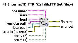
FTP .txt file copied correctly the cRio
I use the 'FTP Get File.vi"to retrieve a .txt file of my CRio, which is then copied on my host. The file is a delimited data tab. The file copied all the data a except that the copy has a blank line between each set of data. These additional lines take me to read the incorrect lines when the file is read in my program later with the "reading a spreadsheet file. These additional lines come I checked the original on the cRio file transfer via MAX and these lines do not exist. Can someone tell me how to solve this problem? Thank you
If you look at the entries for the File.vi FTP Get, you will notice that there is one that says binary:
By default, this is false, which means that it copies the data in an ASCII format. Try a real constant of wiring to this entry. It's the need for VxWorks and Windows use different end of windowing. This difference is probably the reason that it is adding lines to it.
-
What is the MTBF method, used for the cRIO 9012, is the method of counting of Telcordia under what conditions? (Temperature, humidity, etc.)
Hi jojosalud,
According to the specifications for the cRIO-9012, the MTBF is 330 481 hours at 25 ° C; Question of Bellcore level II.
Kind regards
-
MAX does not see the cRIO modules!
Hello
I have a cRIO-9073 and C 3 (9401, 9239, 9263) modules installed in slots 1-3 respectivly. I can configure the chassis correctly upon arrival 2 months ago and I managed to acquire by a module 9234. Now that the 3 mentioned c modules arrived I installed and have a problem - MAX of nothingness, or analysis of LabVIEW RT engine cannot see modules. Attached are MAX.png and DiscoveryStatus.png that depict. NOR-RIO is version 4.00 and corresponding set is completely downloaded to the cRIO. I do not understand the concept of software cRIO yet but I'm positive, that is the same as used to work the first time that I had tried. The network is OK - host is 100.0.0.1, cRIO is 100.0.0.100 and they see.
I susspected that perhaps specific drivers are needed for these particular C failet, but I can't verify that the status of software.
Basic details to accept and understand the CompactRIO concept is spread across many different documents, and it's really hard for the newbees to grasp, so debug/fix situations.
Does anyone have an idea what is causing my problem?
Thanks in advance,
-
Extraction of fundamental characteristics - Watchdog Agent VI could not download the cRIO
Hello
I design an application in real time on one OR cRIO-9022, using the Watchdog Agent made by IMS Center toolkit.
During the loading of my VI on CompactRIO, I get the following error message:
Deployment SoundVib_Resampling.lvlib:oa_CIC Interpolation Interpolation Filter.vi Filter.viSoundVib_Resampling.lvlib:oa_CIC loaded with errors on the target and was closed.

LabVIEW:  unable to load the shared library sndvib. *: OatCICInterpolatorByMovH:C. to ensure that the library is present on the target of RT. MAX allows you to install software from OR or FTP to transfer custom RT target libraries.
I found that when I place the 'base Feature Extraction' VI within a 'disable diagram Structure', the deployment was successful, then the problem comes from this VI.
The error message tells me to install a library on the cRIO, but I don't know where to find it.
Thanks for you help,
David
Thanks Benedict,.
The 'noise and vibration' driver installation on the cRIO solves the problem

-
Hi, just got my new cRIO-9067. I have converted my project over the cRIO-9067 since the cRIO 9074. Same layout module, same engine, same scan code custom fpga, (hybrid mode). I have no problem of compilation for the 9074, which is a lower performance FPGA architecting the 9067 FPGA.
The final timetable for windows compilation shows that the timing is respected for all clocks - 40, 80 and 120 MHz (I use a clock derived for some code sctl). During the end of compilation, during the phase of gen bitfile, I get the dreaded time violation. Investigation of the breach indicates that it is not the custom code, it is not schema components. One of them seems to be linked to the card series OR 9870 I in the chassis.
Why? Is there anything I can try with the compiler directives for this problem? You would think that it would be easier to compile for the highest performance FPGAS...
OK, don't ask me how I thought this output - to run I changed nothing else than this: feed the I/O node a reference FPGA of e/s instead of configure the node via the menu "link to. It makes no sense, but the compilation succeeded when I did this.
I know it is because I created a very simple test VI in my project and made sure it does not compile without it.
-
Hey, thanks in advance for any help.
We are trying to open a file executable file (for example the Minesweeper) which is located on the computer via the cRIO, however we cannot use the Exec.vi system for that (maybe we use it wrong and can we?) Is there another way to do this? We try to use our robot as a joystick to play games and therefore need send keystrokes to this .exe, that we are trying to open. I can do typing when executing power off the pc, but cannot open the .exe when running through the cRIO.
Concerning
Power supply Guy
Hello
What I would do here, is to have two screws, one on the robot and the other on the computer. The robot one will send commands to the computer (host) through shared variables, tcp/ip, UDP, or stream network (essentially a method of network communication). The host that VI will take orders and start the game and actually enter the "keys".
You try to do this without using any code that runs on the computer? If so, it will be much more difficult.
-
The model Interface Toolkit does support the cRIO-9068 again based on Linux?
Hello, I have a cRIO-9068 and need to integrate a Simulink model in my controller. The model Interface Toolkit does support the cRIO-9068 again based on Linux? Besides, don't Veristand? This page assumes that it is not:
http://digital.NI.com/public.nsf/allkb/2AE33E926BF2CDF2862579880079D751
Thank you
Hi Southern_Cross,
Based on the readme:
http://digital.NI.com/public.nsf/allkb/D3F40C101B66128186257D020049D679
It seems that it is now supported! These resources should provide a few more details:
http://zone.NI.com/reference/en-XX/help/374160B-01/vsmithelp/mit_model_support/
http://digital.NI.com/public.nsf/allkb/E552B0CD4E48215586257DF7005BE055
Please note that NI VeriStand 2014 can't stand it targets NOR Linux in real time.
Kind regards
-
Using the CRio NI9265 module as current source
My apologies for what is pretty basic - I come to this Chem Eng background rather than electric. I have a CRio-9012 controller with a 9265 module 0-20 my (among others). The power supply to the CRio is 24VDC. I want to use one of the outputs as input to a power controller Watlow DIN-a-mite, which will lead in turn 10 a / 2.5KW heating.
The datasheet for the power controller indicates that the input command is powered by current loop linear, 4-20 my DC, requiring an available with 6.5 VDC power source. Am I right in saying that I should compare 6.5 VDC voltage compliance for this module (12 DC max), so this arrangement work?
Kind regards
Chris.
Hello ChrisTighe,
That's right, that the installation will work.
The 9265 will display up to 12 VDC, and your device requires a maximum of 6,5 VDC.
Maybe you are looking for
-
Toshiba 4300 39 L - this dongle WiFi WLM chipset - 40U does support
I bought Toshiba L 39, 4300 without dongle WiFi WLM - 40U and I'm going crazy... I understand that I can't buy any adapter and the chipset of the dongle must be the same as the original dongle WLM - 40U If anyone has the same dongle WLM - 40U then pl
-
Sync ipod Nano to the spare computer
I would like to sync my iPod on another computer that I have "authorized". When I try to synchronize, put in guard lose all of the music on the iPod scare me off the coast. The original computer I used to charge the iPod crashed and burned. It can't
-
Hello I'm having a problem with my results file. If I run the sequence on the development of Pc teststand, it works fine, but when I deployed the code and run it on a PC deployment the HTML only summary shows only the first failure. for example 4.1
-
Sorry, I think that question maybe a lot of time, I just want to ask about W510 i7-720QM maximum RAM is 16 GB? Thanks for looking through and answer!
-
Windows 7 - new update - Code 646 - that occur repeatedly for about a month now
Hi all! I use Windows 7 Professional 64-bit. For the last month, my automatic updates continually seem to fail with an error Code 646. My only option so far has been to manually download the updates myself. Just curious to know if anyone knows if the