Timestamp of waveform
I use DAQmx and I use playback function with the polymorphic form of wave 1 d instance. I read just 10 channels of analog voltage data, but I'm using waveform is because I need timestamp for each sample data. I also need the multiple samples, this is why I do not use unique example of polymorhpic.
With ten strings, I extract the data of Y and then concatenate all the values in a 2D array where each channel column represents a data channel. I am trying to extract the timestamp of the waveform to aid (get wave component t0), however, how do I get the timestamp in a form that can be concatenated with other data 1 d? When I convert it to double just gives me an element and not a data table. If theres only a timestamp for each 100 as data lines of tension.
Please see below the code.
What is the point of converting a 2D dbl? You can use export waveforms for spreadsheet file and the math will work with waveforms. And please, use a unique Index table function. It is expandable by simply dragging the lower part down.
Tags: NI Software
Similar Questions
-
get the timestamp of waveform data
Hi all
I'm coming out of the timestamp from waveform data if this is possible. I am writing to file, but the express vi does not allow for fractions of a second and when I write a string waveform data for use with writing to the worksheet, the data of time is lost.
any suggestions?
Use Get waveform components. What part of VI? Writing to a file of measure written fractions of a second.
-
Write timestamps of waveform with data in PDM file
Hello
I try to write data to a table of data from acquisition of DAQmx multi sample, but I found where I have used get date / time in my time function loop past a PDM write in series with another transmitted waveform data, I have more than the timestamps data points, I'm getting a timestamp then the list of the sampled points.
I'm looking for using the timestamp of the waveform data, but I don't know how to do this job. Attached, is an example where I tried it, but just managed to get the incompatible data types.
Could someone please offer some tips on how to get the following structure in my file:
timestamp of the sample. channel 1 sample | example of channel 2. .... | example of channel N
Thank you
Dave
I'm not quite clear about your use case in the attached VI. However, you must provide input of channel names at 2 knots 'TDMS write' since they have different types of raw data.
-
file lvm recorded with time stamp graphic display
Hello
I have headaches display my data with correct timestamp. There are so many methods to save the data. Here, I decided to save it in a text delimited as lvm. a screenshot of my vi segment is attached. I want to use this way rather than other methods is the flexibility it offers. I'll be able to add more data to store that I develop the vi. (So I'm storing data of the DAQ assistant and my calculated values.) I've attached a screenshot of the file I also read.
I would use another vi to open this file and it draw a chart/graph to show a trend of the acquired data. Can someone pls Advisor mid on which is a better way for mi to do?
Thank you very much!
POH
Hi Malou,
Sorry for the late reply, I was rushing to complete my project, has not been able to answer.
Yes, I managed to solve it. In any case, I've used this high rate in the acquisition of data wizard is to allow the acquisition of continuous mode & use a software filter instead of filter material. However writes to the folder this way - write string in .lvm, max is 10 samples/s unless I have use tdm (I'll then everything in the newspaper).
I was not able to display the correct timestamp was due to the fact that I have does not add to the timestamp of the start time for the timestamp in waveform display. I won't be able to go down to my lab, & my machine have no LabVIEW, so what I do is to extract some parts of my report to share.
For the part that I used to display the graph (can be seen on the attachment), I deleted the 1st column, which is the time stamp (for display of the spreadsheet), but extract the 1st element - convert timestamp DBL it when I start recording in the DAQ vi (written with the header).
This excerpt (which could be considered as a group of numbers in the file lvm) and converted to the type timestamp and wired for generating waveform block, providing the start time of the wave.
Then I replace the use of the chart with graphic, graphic is suitable for data acquired and graphic tracing is better for the time of execution of the data display. now it seems to work fine for me, except for the load time may take some time for larger files.
Thank you for your participation in this thread!
See you soon!
POH
-
I am using get date time in seconds, the function to send the date and time to a sub vi where I can use it to calculate the time difference in timestamps of waveform and the hour when he began to get the time in seconds. So I wanted to know if I pass this value to a sub - vi will be this value constantly updated in the sub - vi or it will remain constant until the sub - vi is finished.
Yes it will remain constant because the time was read only once, to hand. Any value is passed to the Subvi remains the same. If you want once updated, you must put the function get Date/time inside the Subvi.
-
Why my sample rate does not match the output of timestamps in the waveform?
Hello
I run a simple application to read the data of two pressure sensors output signals 0 - 5V to a NI9215 module, and one connected to the 9237 module load cell. They are housed in the 9172 chassis.
I am new to DAQ and labview, and I find it difficult to reconcile the sampling frequency that I put in the sample clock and the apparent rate data (according to the timestamps in the waveform that I output to a text file). For example, if I ask 100 Hz rate (and 10 samples to read), the data appear to sample at 1612,9 Hz. If I ask the sampling frequency of 1000 Hz, outgoing data is 1612,9 Hz to 20 kHz, the data came out to 25 kHz.
Can someone tell me to trust the timestamps given in the waveform that is written in the text file, and if there is a way to check this? If this timestamp is correct, how can I force the application of sample data at the requested speed?
As a secondary issue, in my attached VI, you can see that I have an attached to an array of construction shift register. I can't understand how to initialize the array outside of the loop as it clears the table before the next time I run the program. Any advice?
My VI is attached.
Thank you
Claire.
Hi Marc, thanks for the quick response and the right explanation. It's all much more clear now.
Have a great weekend,
Claire.
-
How to record a digital waveform with timestamps for each sample?
I am generating a digital stimulus and capture the digital answer using 6552 HSDIO. The captured response is data digital or forms of digital airwaves.
I want to save the captured digital answer and save it in a file in spreadsheet showing the timestamp for each sample. How can I go to a digital waveform to a worksheet that contains all samples and timestamps for each sample?
Comvert digital to analog is just the wrong function. And when you converted to U8, you just threw the calendar information. Try the code below. He puts the time in a single column. If you want to only two columns, its an easy mod.

-
Timestamp problem DAQmx waveform
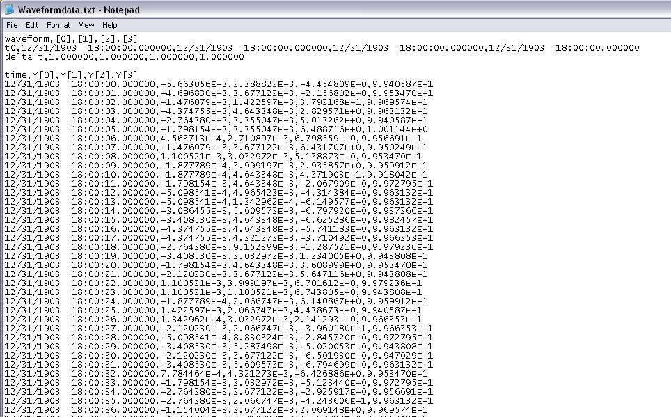
I have a program that reads analog signals multiple DAQmx using a PFI trigger from a DIO card to start the acquisition. It uses a registry to offset and Boolean logic to stop the DAQmx read the loop when the trigger is low. I traced the result to a curve of waveform. I have a 1000 S/s scanning speed. I traced the data to a graph of waveform and eye on the individual data points and it is perfect. Exactly 1 S/s. The problem: when I increase my 5000 S/s scan rate... I see exactly 1 S/s, but the displayed duration of my test data is 5 x more time. That tells me that my graph of the waveform is plotted in fact each data point individual 1ms apart. So basically, there a 1ms all dt in the waveform, and it does not change. How can I get the real dt of the analysis of data here instead of this arbitrary constant? When I look at a text of my waveform data file, I see the timestamp below where I'm expecting something ending like that... 0,0010, 0,0017, 0.0025, etc.. Any help would be appreciated. I'll post the VI if necessary, but other than the trigger power, is a fairly straightforward HERE DAQms read. Thank you in advance.
The time of LV start date is January 1, 1904 midnight GMT. Since your shows up to 6 hours before that, he must be GMT - 6. My horodateurs base are 19:00 31/12/1903, which is GMT - 5. Eastern time zone.
Are you any error coming out after your Subvi waveforms?
You empty an array of waveform data to add. The default waveform has a T0 zero and a detachment of the 1. In the Sub - VI of waveform append inside your Subvi if dt' it does not raise an error, (in fact a caveat being the 1802 error code is positive.). But she proceeds to add data and use the dt and T0 the first waveform which is initially as the default data in the initial iteration. I think that if you start with an array of wavefrom that has the number of channels of the need, an empty array of Y, but a correct dt. Then the dt should be correct. That, or you can put in your Subvi a case structure where the first call, or if the incoming waveform is empty, it is not add and uses only the 2nd waveform.
You have also a little a Rube Goldberg enters your Subvi. It could be simplified as shown in the picture as an attachment.
-
Get the output of waveform of table 1 d by helping the timestamp
Hello
I'd appreciate if someone help me.
I read the temperature of a device. I would like to see the results of temperature of waveform. I code timestamp in the Panel (attachment). But after running, as you can see the time is always zero during temperature changes. It should show the temperature at different times, as time passes.
Kind regards
Mehdi
-
Add the waveform, keep the timestamp
I'm reading of a module of 500 Hz USB data acquisition. To achieve this within the period of the loop, I need to acquire several samples per loop. Once I have these samples (waveform output), is it possible to add the waveform that keeps the timestamps?
I am currently using the 'time to get picture', and then insert the data into a the same shift register. I would like to re - insert the data in the rest of the waveform added to simplify the writing of information that much easier. If this does not work, I'll probably just to do a string 2D array to write the data.
Thank you!
-
How can I add a timestamp to the "big grid" movement of a waveform graph?
Hello
I use LV 8.5.1
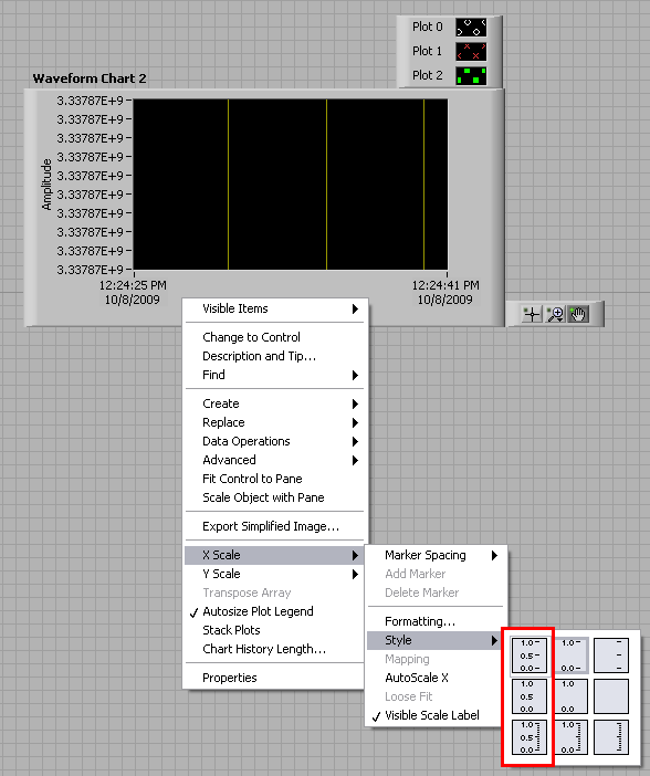
I use a table of waveform and I turned on the "outline of the grid" by using the Properties tab of my map of waveform. (properties--> scale-> grid lines)
When the code runs, I want to fix a grid line to each yellow movement of time stamp.
So as the grid lines move from right to left, there is a timestamp associated with each.
If anyone can help!
Thank you
J
hova2010,
If you right-click on your chart and go to X scale > Style > then choose one of the 3 styles on the far left you shoul see horodateurs for these grid lines.
-
Displays the absolute time of a waveform channel
Hello
I would like to display the absolute timestamps on the x axis of a 2D graph in the DISPLAY of the waveform channels in a PDM file. The timestamp of the first sample is stored in the wf_start_time property.
I found this article , but I don't want to generate a weather channel because the benefit of waveforms is to avoid storing the part x of the signal in the files.
Is there another solution since 2007?
I use DIAdem 2011 and LV 2011.
Thanks in advance
Hi Yohanna,
The only way to display the datetime values on the x-axis of the graph in SIGHT and the only standard way to do the graphics in the REPORT, is to create a DateTime String. DIAdem in 2011 it is much easier to do, since you can use the standard ANALYSIS function "Generate digital channel", by selecting the option buttons 'values of x-part of a waveform channel' and 'Create channel time (with absolute time reference). You can also use the standard ANALYSIS function "digital channels <==>waveform.
Brad Turpin
Tiara Product Support Engineer
National Instruments
-
With an average of 10 channels of waveform separately
I've written a VI that takes input from 10 different devices then shows in several graphics and then saves in PDM. This works perfectly well. The problem is, on my PDM data, is saving 25 samples per second creating a file of long worksheet for short durations. Im trying to figure out how to reach an average of each channel independently (average 25 samples) and print it out every second, so there should be a 1:1 ratio between my timestamps and data, not 01:25 how it is now. Thank you!

Personally, I just averaged 100 samples you take. If this simple solution is to replace your table decimate (inside the square structure) with a Mean.vi. You will need to use a range of build with a single input to transform a table to write in the waveform (still inside in Place element Structure) of the average.
-
Well, I take (multichannel ADC) entry of A Microcontroller.i.e uC 6ADC uC has done its job and sends serial...
My problem is when I use a waveform of writing file...
the PDM contains more than 2 values at once
That's why when I o/p is the evil waveform... its much igger (sense of time)
How to build a waveform with instantaneous values of Amplitude
What is the file .tar you home?
Looking at your screenshot, I see the timestamps in your table. You rely on Windows calendar to get the timestamps? Do you know that Windows has only a resolution on its clock of approximately 16 milliseconds? That's why you see several pieces of data with the same time, then he jumps 16 milliseconds.
-
Timestamps and measurement file express VIs
Hello
I want to do something simple: record crossing of a few channels of scalar data for a measure that could take several hours. I want to record the data inside the loop so that no data will be lost if something breaks down.
I ended up using the express VI "Write to a file as", writes a file LVM. (The test code is attached). After many tests, I came to the conclusion that I must address both the "Start Timestamp" and "Timestamp" attributes after converting my scalars to Dynamic Data. Looking at the LVM file in a text editor, I think that everything in logical present at this level.
However, when I read the data comes back with 'Reading a file measure' and post it on a waveform graph, my starting timestamp is correct, but the time displayed is 2 x too long. But if I choose the option relative timestamps in the configuration of express VI 'Read the file of measure', the time displayed is correct. ??? Of course, I want to display the absolute timestamps...
Is this a bug or I'm just something wrong? Is there a simpler way to do what I want? It was supposed to be ambivalent...
All my code is attached. I'm using LabVIEW 2015 SP1 running on Windows 7 / 32.
Thanks in advance for any help!
-Philip
A brief update: I have also submitted a request for assistance on this issue, and the rep NOR verified that it is a bug and introduced a CAR. In the meantime, I used the Datalog screw and found that those who did what I, with relatively little noise.
Maybe you are looking for
-
Photos not in chronological order after updating to the new iPhone 7 since the previous backup
A few days ago, I backed up my iPhone 6 before heading to Verizon to update the iPhone 7 (128 GB). At this point, all my photos are in normal chronological order. Once I got the new phone, I plugged into my MacBook and put in place since the last bac
-
Hi has received as a result of sms today 30/09/2011"Good news!" Your numbers ohone hs wins 750,000.00 GBPonds in Mozilla Firefox phone number attract to the United Kingdom to request, via email only to:[email protected] ".Please confirm that this
-
Dear Sir I used windows xp.and I install google chrome and the "aw" snap error error... so how to solve... pls rep...
-
Frank, Another question. When using the two DVI to TV and VGA for monitor's resolutions be defined automatically? If so, they will be the maximum rates that I previously posted in my other thread?
-
XPS 8700 mSATA drive installation on motherboard
What is the size of screw for studs on the motherboard XPS 8700 mSATA? Also is there a preference as zinc coated or in stainless steel steel and split or philips? Thank you.