Toggle the analog inputs and tasks of output on the same card in LabView
Hello
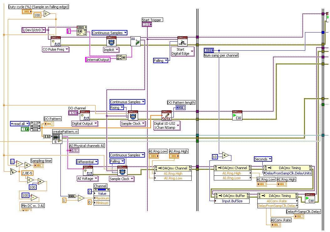
I'm relatively new to LabView and am trying to find the best way to switch between reading and writing tasks on my PCI-6024E. It seems this would be a common thing to do, but I found no good documentation or any relatable example program. Basically, I would like to be able to monitor certain analog inputs and then write that some outputs if an entry is in accordance with certain specific conditions (say > 4 Volts voltage). It is my understanding that you can only signal (input and output) types associated within a single task in DAQmx. I also understand that you cannot have multiple tasks running at the same time on the same material/map, otherwise you get a: 50103 error 'The specified resource is reserved. Calendar is not really all that matters to me, but quite synchronous and effective would be nice.
I have attached a sample program that shows more or less what I'm trying to do. I want to follow several analog input lines (AI0 AI1, AI2 and AI3 and) effectively at the same time. If certain conditions are met, AI3 > 4 Volts, then write 5 Volts for analog AO0 and AO1 outings. I also want to maintain output at 5 Volts up to AI3 falls below 4 Volts. Is there a better way to pass the task to read and write than what I've done here? In a sense, all I really do is toggle of a state machine if the required conditions are met and if start/stop tasks of reading/writing necessary.
One last question, is there a way to display the four channels in the waveform graph using the 1 d NChan 1Samp mode so I can have a time chart and indicators?
P.S. I'm under LabView 2011 on Windows 7. Your ideas and suggestions are appreciated.
Thank you
KJ
I also understand that you cannot have multiple tasks running at the same time on the same material/map, otherwise you get a: 50103 error 'The specified resource is reserved.
This is incorrect. You can't have two tasks of the same type running on a single card. You can have an analog input and analog output task running simultaneously on the same hardware.
You are right that each task can have only one type of task (entry or exit). Discover DAQmx examples in the example Finder to get examples of synchronized input and output.
PRO TIP: In the Finder of the example, go to the drop-down list in the lower left corner. Pull down and select Add Hardware. In the pop-up window, add your PCI-6024E to the right pane. Click OK in this window. Then in the main window of Finder example select your hardware from the drop-down list and check the filter results by the hardware. The example Finder then only you will show examples that are out-of-the-box compatible with your hardware. I am sure you can find something to fit your needs here.
Tags: NI Hardware
Similar Questions
-
Simultaneous analog inputs and one digital output (with NI6221M). Critical moment.
Hello!
Please excuse my bad English.
Idea:
I developed a device to measure the absorbance of light in the sample. The device will have 20 light emitting diodes (led) and 30 light sensitive photodiodes (DP). I have a PCI NI6221M card. As there are a lot of LEDS and PDs the device must use external multiplexing (MUX). The Assembly is shown in figure "DOAI System.JPG". "delta t" figure is not important. It may be zero, one or a few Americans. It is not essential for the operation of the device.
Opreation:
PD 1 will be multiplexed to the AI and the LEDs blinked (turned on and outside), one at a time. Then 2 PD will be multiplexed to the AI and again all LEDS flashing one at a time. The sequence continues with 3 PD, PD 4 and so on. Each blink a led should produce a sample of I. The sampling frequency of the AI should be about 12 kHz (so 80us for example).
Q: It will be possible to obtain from the Commission of NI6221M?
Problem:
I realize that there will be problems. When c generates an address on the MUXs there will be a delay until the LED driver, PD and input amplifier electronics of HAVE it settled. Q: Is it possible to delay the sample clock HAVE some 10 microseconds as to allow that to happen? (Perhaps use an internal counter operating on a basis of time much faster than 12 kHz sampling or use another for me still a feature is not known. May actually leave the sample clock HAVE be the 'master' and instead of delay clock.) Please see the "" calendar of GOT it. "" JPG ".
Q: Is it possible to control the time to settle for AI? That is to say that he can use the 6221, say, 30 US to settle before it reads the value. What these 30 arrive us before or after the flank of sample clock?All reviews are much appreciated,
Markus
Hello!
Just thought I should fill this thread by posting the code that we use now. The moment is as before, but we've added a few nodes property to coacha few parameters. In addition, 6221 has been replaced by a 6259Usb device that allows us to have the best insulation galvanic and more synchronized digital I/o lines.
-
How to synchronize the analog input and the output of two different USB data acquisition boards
Hi all
I have two tips very different USB NI USB 6008 case, which I use to acquire the data (analog input) and a USB of NI 9263 is a output analog only site I use to route a signal (in this case a square pulse). The reason why I use the outputs analog 6008 is because I need to deliver negative tension and need the full +/-10 v range.
Looking at similar positions, I'm pretty sure that I can't use an external trigger or a common clock, I also tried to use the timed synchronization of the structures but no cigar.
I'm including a quick vi I whipped showing how the jitters because of the lack of synchronization signal. The OD of the 9263 connects to AI in the 6008 in this example.
I talked to a specialist in the phone and tols me that's not possible.

-
analog input and output synchronization
Hello everyone, I seem to have a problem of synchronization of the analog input and output on my M-series USB-6211. My request is quite simple. I want to the production and to acquire a sinusoid at the same time. Theoretically, I should have the same 4000 data points through the input and output channels. The reality, however, captured on an oscilloscope, shows that the analog output is off more than 4000 data points. The entry (acquisition) shows 4000 samples. Please see below an excerpt from the creation of task, timing and execution. I'm afraid that the analog input and output are not attached correctly. Do you see something suspicious? Thank you very much! The task was created: DAQmxCreateTask("",&inTaskHandle); DAQmxCreateTask("",&outTaskHandle); Analog output channel Configuration, with 20Ksamples/s: DAQmxCreateAOVoltageChan (outTaskHandle, physChanOut, ' ',-10, 10, DAQmx_Val_Volts, NULL); DAQmxCfgSampClkTiming (outTaskHandle, "OnboardClock", 20000, DAQmx_Val_Rising, DAQmx_Val_ContSamps, 4000); Configuration of the analog input strings: DAQmxCreateAIVoltageChan (inTaskHandle, physChanIn, "", DAQmx_Val_RSE,-10, 10, DAQmx_Val_Volts, ""); DAQmxCfgSampClkTiming (inTaskHandle, "OnboardClock", 20000, DAQmx_Val_Rising, DAQmx_Val_ContSamps, 4000); Set up the trigger: sprintf ("/%s/ai/StartTrigger", local_port, deviceName); DAQmxCfgDigEdgeStartTrig (outTaskHandle, local_port, DAQmx_Val_Rising); Output: DAQmxWriteAnalogF64 (outTaskHandle, (numberOfSamples * oversample), 1, 40, DAQmx_Val_GroupByChannel, input, & sampsPerChanWritten, NULL); Acquire: DAQmxReadAnalogF64 (inTaskHandle, 4000, 40, DAQmx_Val_GroupByChannel, readArray, 8000, & sampsPerChanRead, NULL); The tasks stop: DAQmxStopTask (outTaskHandle); DAQmxStopTask (inTaskHandle);
Hello
Change the finished continuous sampling method seems to solve the problem:
DAQmxCfgSampClkTiming (inTaskHandle, "OnboardClock", 20000, DAQmx_Val_Rising, DAQmx_Val_FiniteSamps, 4000);
Also, I wanted to say earlier to write 4000 samples:
Output:
DAQmxWriteAnalogF64 (outTaskHandle, 4000,1, 40, DAQmx_Val_GroupByChannel, input, & sampsPerChanWritten, NULL);
Thank you
-
Analog input and output using 5640r
Hello world
I'm Christine, I'm implementing OFDM on fpga using 5640r.
The code that I have, which is good in the simulation using labview and also using 'nor 5640r treatment only' but I want to implement in "analog input and exit vi" so that I can send and receive on the same card 5640r
After so much attention in this regard, I am still unable to find the issue, then the soultion to this question. something that I am able to understand that maybe there would be some questions (ADC and DAC) clocks the clock setting
I have attatched that vi. Please take a look at
Concerning
Aqib
College of aeronautical engineering
Risalpur
Sorry
-
DAQmx: Outputs digital multiple tasks for the same card using the on-board clock
I have a PCI - 6259 DAQ I'm programming with DAQmx. I want to create two tasks of digital output on the same card. A single task using on-board clock, continuous samples. The other task uses an onboard clock, finished samples and an external trigger with trigger Start.Retriggerable property = TRUE. Is this possible with my hardware and DAQmx? There will be a conflict if two tasks use the same clock source?
This is not possible, you can have only one task timed materially by device.
Best regards
-
Now I have to add the same card, because the security code disappears.
Take a look at this article, it can help you change or delete your Apple ID - Apple Support payment information
or you can also contact - official Apple Support
-
6 of Lightroom cannot read my Canon 5 d Mark III photo files, the import message I received: the following files were not imported because they could not be read. I use the same camera that I used Lightroom 5 with the same cards Compact flash. The files are: DK5A0243. CR2
Lightroom 6 trying to copy pictures to a different directory than what is Lightroom 5. That's why you have the problem.
You can change the directory where you are teaching LR 6 to place photos, or change the permissions on this directory to read & write.
-
Synchronized analog input and output on myRIO
Hello!
A brilliant new myRIO just landed on my desk and I'm looking forward to learn how to use it.
I have a question about the ability of the default FPGA personality.
Is really similar synchronous HW in and output possible? Can configure you the necessary trigger and clock routing from within VI RT? To say ~100kS/s?
I need to delve into a FPGA design to achieve this?
Thank you!
You will not be able to get your RT loop to run reliably at rates greater than 5 kHz, and we generally do not recommend trying to control I/O faster than 500 to 1000 Hz. This isn't a limitation of the default personality himself, it's just that some tasks are better suited for the OTR and some are better for the FPGA (it is important to understand when developing an application on the myRIO). Synchronization and the output of ~100KS/s signals are something that you have to do on the FPGA.
http://www.NI.com/Tutorial/14532/en/
There are some good tutorials in the link above. They use the cRIO instead of the myRIO but the functionality is basically the same. The biggest difference is that you won't have to add modules to your project, because all the inputs and outputs of the myRIO are fixed and must fill out automatically when you add a FPGA target to your project.
-
What is the minimum response of analog input, through DSP online, output analog time?
Hello experts!
I want to know if it is possible to get a very quick response latency (~ 1 ms) sound recording (analog input), through online registration (DSP online), the presentation of his (analog output) processing, by using the DAQmx programming codes. My system of NEITHER includes NOR SMU 8135, SMU 6358 DAQ Multifunction controller and SMU 5412 arbitrary signal generator. I also have access to the latest version of Labview (2015 Version) software.
My project is on auditory disturbances, which inovles record vocalizations, manipulating the recorded vocalziations and then present the manipulated vocalizations. My current idea of how to achieve this fact triggered output voltage after reading the input using DAQmx Read samples. DAQmx Read output is filtered online and then passed as input for the DAQmx writing for analog output. For purposes of illustration, examples of code are presented below. Note for simplisity, codes for the trigger part are not presented here. It's something to work in the future.
My question here is If the idea above should be reaching ~ 1ms delay? Or I have to rely on a totally different programming module, the FPGA? I am very new to Labview so as to NEITHER. After reading some documentation on FPGA, I realized that my current hardware is unable to do so because I do not have the FPGA signals processing equipment. Am I wrong?
Something might be important to mention, I'm tasting with network (approximately 16 microphones) microphones at very high sampling rate (250 kHz), which is technically very high speed. Natually, these records must be saved on hard drive. Here again, a single microphone is shown.
I have two concerns that my current approach could achieve my goal.
First, for the DAQmx Read function in step 2, I put the samples to be read as 1/10 of the sampling frequency. It's recommended by Labview and so necessary to avoid buffer overflow when a smaller number is used. However, my concern here associated with the latency of the answer is that it might already cause a delay of 100 ms response, i.e. the time to collect these samples before reading. Is this true?
Secondly, every interaction while the loop takes at least a few tens of milliseconds (~ 30 ms). He is originally a State 30 late?
Hey, I've never used or familiar with the hardware you have. So I can't help you there.
On the side of RT, again once I don't know about your hardware, but I used NOR myRIO 1900, where he has a personality of high specific speed for the RT where I can acquire the kHz Audio @44 and process data. Based image processing is ultimately do the treatment on a wide range of audio data you have gathered through high sampling frequency and number number of samples as permitted by latency, please check this .
I lost about 2 weeks to understand host-side does not work and another 2 weeks to understand the even side of RT does not work for online processing (real time). Then, finally now I'm working on FPGA, where the sampling rate is 250 kHz (of course shared by multiple channels).
The complex thing with FPGA is coding, please check if the filter you want is given below as labview automatically generates some codes of some filters.
Most of them will work in 1 SCTL IE if your target has 40 MHz clock algorithm will run in 25 ns. That's what I was looking for, I hope you

See you soon... !
-
Input analog FPGA and scale of output
Hello world
I'm looking at the code of the analog and exit entry in the example file. Why the signal at the analogue output is first divided by 10 and multiplied by 32768 and the signal at the entrance is first divided by 32768 and then multiplied by 10. Are there specific reasons for it? This is due to the internal structure of 7831R I use?
shuishen1983,
Who is scaling to HAVE it / AO on map R series FPGA. With these FPGA cards actually face GOT it / AO on a level of material such as you are reading/writing the actual values of the ADC. I mean, it's that your HAVE is 16-bit resolution over a +/-10V range. To get the voltage in your program, you will need to convert the readings of the ADC in significant values.
2 ^ 16 = 65536 (16-bit resolution = 65536 values, represents this 65536 - 10 v to 10 v)
Example entry:
Input to the FPGA card voltage is 5V, which will appear as 49152 on the ADC. To get significant value, follow the calculation below.
49152 (reading the raw ADC) - 32768 (account for negative numbers) = 16384 (I think the subtraction of 32768 is done in your FPGA to account for negative numbers, that the code is not attached, so I'm not sure)
16384 (value at the level of the ADC) / 32768 (input range) * 10 = 5V
Example of output:
You want to generate - 5V
-5 / 10 * = 16384 32768
-16384 + 32768 = 16384 (once again, i belive this negative conversion of the addition of 32768 is made directly in your FPGA code)
16384/65536 =.25
.25 * (10 - (-10)) = - 5 v (located between-10 v to 10 v, then convert it to a "full range" of the 20V)
I would like to know if this helps or not!
-
Analog input and contrary to the worksheet
Hello
I m trying to get an analog input (volts of a sensor) and a counter with an encoder. I ve long time looking for a solution and I ve already found some very useful examples that I ve used on the VI (thanks for that
 ).
).The program is very close to what I want, but there are still a number of things that I don't understand (I m very new with labview and I still Don t know exactly what I m).
-J' read in an example here that I should use "Single Point timed material" and use the "wait for next sample clock VI' to get samples always with a period fixed (rate). It's works! Before, I used "continuous sample" and it was a bit jitter. Well, could someone explain to me please what is the difference between continuous and timed, material and how the 'Harware Timed Single Point '.
-My second question is about the string formats that I receive on the loop of the wave. I ve tried with very different formats, but it doesn´t work as I expected. I have a format string like this on the 'Date Format VI': %S % 3u-online seconds with 3 decimals?
And on the format I have on the 'picture to a worksheet VI string' should I used %5.7f to get 5 decimals on the output (spreadsheet file). Why?.
What I m trying is to get the analog input with counter clock (I think I already do), given a graph and a file with lines of 3: 1 °-time with 3 decimals, 2 °-v with 5 decimals (positive and negative) and 3 °-position (positive and negative integer).
Software: Labview 2013, pilot DAQmx 9.8, Windows 7 32-bit
Material: NEITHER 6321 PCIe, Intel Quad 9550, 4 GB RAM
I hope that his undestable, I should learn some English to.
Thank you
Hello
Thanks again for the response. I tried to implement the code as you say, but it's always a mistake to time. I solve it with a timestamp.
The idea of a producer consumer loop was very good. After"a bit", I managed to solve it too. Here's the code.
Thank you
-
Hello NOR community,
I'm new to LabView and was hoping someone might be able to help with a question I have. Currently, I use a data acquisition unit to sample external sine and I would like to change this signal by adding another signal that I could control using the front panel. Whenever I try just connect entry with something like the waveform sinusoidal vi and put a subtraction sign between them it doesn't work (I get an empty waveform graph). To work around this problem, I've resorted to a signal (via an analog output) and followed by reading the signal to data acquisition, and then finally I add the two together. It works this way, but he wastes two channels and I imagine that there is a better way. I enclose my VI, and I have marked the location of interest "where signals get subtracted ', which is currently displayed using two entries.
Thank you
Leo
You must ensure that your sampling frequency and number of samples is the same. It seems that your sample (with default values) rate is the same (1 kHz), but your number of samples is different (100 to 1000 the acquisition wave vs simulation).
-
Open a synchronized session of the analog inputs and position
I want to read 8 analog inputs (only three IA in the capture of code) with a PCI-6221 card at a rate of 100 samples/s, reading 10 samples/iteration. At the same time, I want to read the position synchronized with the analog inputs. Is this possible? If I just merge the position with the analog signal I get 10 readings of position for each 100 analog input readings (see chart - Red's position). For the control of the movement, I use the pci-7342 with UMI-7764 interfaces. Could someone help me out here please?
Not necessarily. As said, speeds of up to 200 Hz should work fine with a 7342. If this is not enough, of course a 7350 could be used, but there is also a completely different approach that should work with your current hardware:
7342, you may also route the phases of encoder to the pins of the RTSI. You can use a counter on the 6221 to measure the position of your axis based on the singlas you have routed the RTSI pins. Now you can use "Measure of Position buffered" (see DAQ examples) to measure the position with the same source of synchronization than your analog signals.
I hope this helps,
Jochen
-
How to merge and write analog inputs, and export data to a tdms file?
I have a vi who writes analog inputs in tdms files. I also want to write the analog output signals, which are 2d table entries in the same PDM file with additional columns representing the analog output signals. How can I get this feature?
Ashaironix wrote:
Hey Crossrulz,
So you're saying that writing two files tdms with entries as HAVE and AO, will write everything in a file single tdms AOs and Ais?
N ° you write in the same file, just different GROUPS. TDMS is a hierarchical data format. You have the file, group, channel. Waveform data will actually in the channel data. But you can have metadata on any level. So, I do a group I and a group of the AO.


Maybe you are looking for
-
HP Pavilion Slimline s5304y: print web page
When I go to print a web page (example a car rental reservation confirmation or IRS form) is really small or cut straight to the page that prints. Sometimes Preview Panel shows the page correctly and sometimes shows it's small or cut off. I thought
-
Windows Movie Maker ceases to meet impossible to publish the movie
Windows Movie Maker stop - impossible to publish the movie Windows Movie Maker gel I can't publish my movie in windows movie maker - fully he gets to 76% and never completely complete edition (I tried several times, but continues to be the same thing
-
choose you one and tell me why? or
-
On windows 7, right click - new - *file* does not appear to create folders, I see other files word, excel etc. are appearing but not "folders". When I try to create Folders by right-click - New, it does not appear. Help, please.
-
Request of the ACC not showing the latest updates
The Adobe Creative red cloud icon does not show me the updates. (VAC is the latest version.) For example, the first on this computer is 2015.3 10.3.0 but I know that the latest version is 2015.3.1.I clicked on the ' Check for updates app ' and after