Trace impedance Locus - resistance vs reactance
Hello
I'm new on using MultiSim and therefore still find my way around. I have a circuit (including essentially parallel RC) and would like to do a scan of the same AC thing. I see MultiSim offers several features for these sub simulation-> analysis-> 'AC Analysis' and 'single frequency AC Analysis. I managed to generate the impedance (Z) vs frequency (f) via the "AC Analysis" method. It's pretty simple.
Now, I want to generate an impedance - i.e. a plot of resistance vs reactance Locus (also called a trace of Cole - Cole, I think), my circuit over a range of frequencies (so as to obtain a locus) as for the route of f Z vs. I tried the "Single frequency AC Analysis" method and I got for the resistance and reactance, but values for a single frequency value, like the real parts and imaginary output (I checked that the values are accurate). So I'm left wondering how I can get this run on a range of frequencies (say 0.001 Hz to 1000 Hz) and achieve a consolidated result. Also, if possible, if I can get directly this drawn see grapically locus.
I went through the forum and video tutorials, but could not get what it is. Thank you very much, in advance!
See you soon,.
Shailesh Marco
Hey that worked perfectly! I was able to trace the real and imaginary parts.
Thank you very much!
Tags: NI Software
Similar Questions
-
What instrument or method can be applied to the analysis of impedance in a circuit?
If this tour has included some capacitors and inductors, the multimeter is not his answer, heihei.
I need get the resistance and reactance circuits in Multisim.
Hey, Fangel.
The best way I know to do what you want in Multisim is to run an AC analysis in simulation menu, under "analysis-->. Set up the bandwidth, and the number of points, etc., the way you want and run analysis AC. After that, run the "postprocessor" (also in the simulation menu) and have it draw or voltage complex to your node of interest from the list. As noted above, the voltage will be equal to the impedance when your test source is a 1a current source.
For example, if my node is v (1), I tell him graphic "frequency", "re (V (1))" and 'im (V (1))', which will produce a table of the complex impedances at all frequencies. See the image as an attachment.
The series resistance is the real part (re (V (1))) and the reactance is the imaginary part (im (V (1))).
Hope this helps,
Ed
-
Rogue Win32/FakeSpypro form somewhere that I know not infected my comptuer left and three times legacy, including the error code above that has to do with the order allowing me to install my choice of applications, such as the PC Tools Firewall Plus 7 that this Trojan horse took control of my computer, even though Microsoft Essentials he cleaned three times. Can someone help me to thwart this Trojan horse so that I can fix the error code 1058, which will allow me to use the Shell commands that allow me to install the applications. I really need the firewall above as the Trojan erased all Windows tools. An email with the solution to this problem will be so appreciated.
Thank you kindly in advance.
Karen Sue Loader
E-mail address is removed from the privacy *.
Win32/FakeSpyPro has probably infected your browser and residual traces that are resistant to disinfection attempts. Rather than running a "Scan with MalwareBytes' response to you, I suggest you follow these steps closely:
1. reboot your computer in Mode safe mode with networking
2. with the computer completely restarted, click with the right button on the taskbar, and then click Start Task Manager. Go to the processes tab and look for these three processes:
Adware_Pro.exe
nwdcsysguard.exe
sysguard.exeIf you find them, select them in the list, and then click end process in the lower right corner. You can close the Task Manager after this step if you wish.
3. go to Start, all programs, accessories, System Tools and then click Internet Explorer (no addons).
4. go directly to http://www.malwarebytes.org and download the free version of their software excellent anti-malware on your desktop or another location. Close Internet Explorer at this time.
5. install MalwareBytes comes from the mbam_setup.exe file.
6. start MalwareBytes and attempt to update the program if updates exist (so the part with networking Safe Mode network ).
7. run a full scan of MalwareBytes . Remove the infections found.
8 restart the computer.
Ideally you should print, PDF or TXT these instructions so that you need to refer to them after the restart in Mode safe mode with networking. If you feel you absolutely have to bookmark or shortcut this thread, only access to the link after step 3 and only with Internet Explorer that is running without addons.
-
Designjet T610: 24 "waterproof or water-resistant paper roll
Does anyone know if waterproof or water resistant paper is sold in rolls 24 "wide with a 2" base for my Designjet plotter? Had no luck finding one. I just bought this used tracer.
Thank you
Check the following two on Ebay & around $60 with shipping.
Premium Glossy Photo Paper Roll inkjet canon hp epson photo RC
I also tried the photo paper glossy HP pigment daily & water launched on it. Pass.
After printing, wait longer and better.
-
I have a question for the SMU 4139.
It is able to program the output resistance/impedance.
Its output can be used to simulate a resistance? Floating? Or he is still stuck to the ground.
THX.
Hi kdCMC,
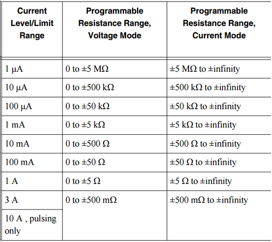
You can program the 4139 NOR as a programmable load. The attached example allows you to use the functionality of the programmable output to the program directly resistance the resistance of the device. To do this using the DCV, set the output voltage to 0 V and the resistance value of the output to a value valid for the given current limit range. DCI mode, set the current 0a output and the output resistance to a valid value for the given value of current level range.
Valid values of resistance are shown below (copied from the technical document):
Note that valid resistance values depends on if you are in mode voltage or DC current. The value of values also depened on the current limiting current level range or that you have programmed.
The load will always float unless you physically short the LO Terminal to the chassis GND.
-
Measure the resistance with PXI DMM 4072 on different frequencies
Hi all
I tried to get on board various and unable to find solutions for that. I'm trying to measure resistance using NI PXI-4072 on frequencey 1 kHz, but not luck. When I try to use Agilent LCR meter I see the correct value of the resistance.
I've seen a few posts on this but don't have no satisfactory solutions.
In above post, someone said that I can use 4072 DMM OR digitizer, does not have a lot.
Can someone please provide the right path for me to solve this problem.
Thank you
Hello Puneet_K,
I checked the data sheet and the method of measurement described in the specifications of the NI 4070/4072 http://www.ni.com/pdf/manuals/371304g.pdf; indicates that the ability is measured using an alternating signal and select the test frequency range, for example 3 kHz, 1kH or 91 Hz. The resistance is simply measured using a DC signal, and it is often sufficient to measure the internal resistance of a battery. If you need a more flexible control for the measurement, you probably get a card like the function generator and then set a multimeter to measure the voltage and another DMM to measure the current and calculate the impedance of these values.
I hope this helps!
Kind regards
-Natalia
-
Digitization and adaptation of impedance of the signal source entries
I'm trying to measure the voltage difference and the time between the two entrances of a USB-5132 digitizer. The switching interval that I try to capture is ~ 150uS and I intend to acquire ~ 25K samples (50MS/s for 500, although it is an overdose of sampling frequency). The digitizer is 1 M ohms entered and I wanted to use the 100 SMA 50 ohm cables to connect to the source of the signals which in addition to several kohm impedance. My knowledge of RF is low and I am concerned about the impedance matching between the digitizer inputs, impedance source and wiring. What kind of considerations to I need to avoid degrading the signal? The switching signal is pulse-like and is rich in harmonics and on a sample of 500K samples/s scope is represented accurately. Should what kind of considerations I do about the impedance?
Hi William,.
There will be some problems if you try to use a source that has an impedance of several kohms. You will probably get the reflections of signals. What is the source of your signal has several kohm impedance? I'd take a peek through the following article Developer area that describes some of the considerations when it comes from impedance matching. Specifically, I would check the last section corresponding resistive. This should give you a better idea of what to worry about your application.
http://zone.NI.com/DevZone/CDA/tut/p/ID/3475#toc4
Here are also a couple more developer area articles that you might be interested in what concerns your situation.
http://zone.NI.com/DevZone/CDA/tut/p/ID/5779
http://zone.NI.com/DevZone/CDA/tut/p/ID/2892
Chris W
-
Hello
We use the DMM and SMU-6363 map to test a hardware device. We will also use a PXI-2530 b switching matrix. We will use the digital multimeter to perform the measurements of voltage, DC and AC, measurements of impedance (2-wire and 4-wire), frequency and waveform acquisition. Can the PXI-4071 left be 4 wire connected (black jacks taken connected and red connected) mode and still be used to perform all other measures (including 2 impedance of the cable). This would simplify the switch connections.
Current measures use the son + and LO, but the HI and S-can remain connected. The problem you are having is if you have an active device the digital multimeter and take you a 4-wire resistance and the measurement of voltage with all 4 wires connected and then change to a current... When you do this, short-circuit you the terminals of the DUT, on that you just take the measurement of the resistance. If the terminal HAD, say, a power supply 10V, then you have just shorted out. Of course, this isn't a problem if your Instrument is a passive device, or if you change just the unused two lead whenever there is an active device of low impedance.
If you want to make voltage, current and 4-wire resistance, you need all 4 wires. If you want to do the voltage and current, you will need 3 wires, but you could connect the s + Hi and then just do the two wires. I vote running every 4 son to your DUT for maximum flexibility.
2-wire resistance is a must if you are measuring resistance above 10 MOhm. Alternatively, you can use 4-wire for all measures.
-
Impedance and exit Angle of Phase with Keysight 4294
Hello
I use LabView to run my 4294A Keysight impedance Analyzer. I was able to get the program to initialize and configure all settings and take the date of clearing the open and short my 16047 D test set-up. After that I'm sticking my OTC in the son will continue formatting graphics and the autoscaling them. When I use the memory tables and reading of data to view graphical waveform data and a table, the | Z | data (impedance) are displayed correctly but I have not been able to get to the exit data (phase) of theta will display correctly on the graph or table. I tried switching active traces and use several functions to read but so far I can't make it work.
Anyone know how to make this work?
Thank you all,
Logan
T..
I could understand by comparison with another measure of instruments that the secondary output is the impedance of the imagination and here to compute the phase angle using the arctan of the imaginary in the primary. Thank you for answering my problem and I hope that this thread can help someone who has the same problem.
Logan
-
Hello
I would like to acquire a PWM signal of 0/24V with the NI 9401.
I'm doing a voltage divider (R1 = 2.375kohm, R2 = 0.625kohm) to lower the PWM signal to 0/5V.
This two values of my resistance works only if the input channel of the 9401 impedance is greater than R2.
Is it OK to do it this way?
What is the input channels of the NI 9401 impedance?
Thank you
Hi Alexandra,.
Thanks for posting on the forum of National Instruments.
The input of the 9401 impedance is 47Kohm, so it should work with your voltage divider.
Kind regards
-
NI USB - 6212 BNC analog input impedance matching
I just ordered a case NOR USB - 6212 BNC DAQ (should be delivered soon). I want to use to measure HV signals using a probe of high voltage of 1/1000 I have.
Now, datasheet of the probe (not a lot of info) says it has an impedance imput 100MOhm. I suppose that it consists of a simple resisitve divider, and if the ratio is 1/1000, I wait so to have a 99.9MOhm resistance in series with a 0.1MOhm resistance. However, the data sheet also specify that the probe is designed to be connected to an oscilloscope with an impedance of 1MOhm. As this input impedance is very low compared to the low value of the separator of resistance resistance, so I guess that the real resistance at the level of the sensor values 99.9MOhm and 0.11MOhm (to obtain the 0.99 and 0.1MOhm when it is connected to the oscilloscope for 1mW).
Therefore, given that the impedance of the USB-6212 according to the datasheet, the analog input is > 10GOhm, I expect to measure higher to true alternative voltages when connected to the acquisition of data from 10%. This assumption has a meaning?
What would be the best way to get around this? Do a calibration and correct the values acquired in LabVIEW code? Or should I add precision 1MOhm resistance at the same time to the acquisition of input data to decrease its resistance to entry to the value expected by the probe?
Thanks for your help!
Since you have a range of 1000: 1 I guess you also need bandwidth (I have a TEK 6015 A
), so you need based on the impedance input, a complex value, means he must not only watch but also the ability to input resistance (1 M). demarcation of the field probes have usually some elements of toppings to match the probe and the input scope. RTFM of the help of the probe
BUT a more serious point is that with your probe, you have a very high resistance. And if you look in the specification of the 6212 you will find on page 2 by mistake ppm in logarithmic scale graph! and even 100 k source impedance it not shown.
So I'm afraid that a simple 1 M on the DAQ entry can work if you're only measuring DC, and only if you use a channel on the acquisition of data. A workaround is an amplifier separate buffer with an impedance of good entry corresponding to the specification of your probe and a low output impedance.
-
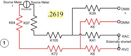
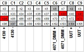
I have a problem with a PXI-2530 switch card work in matrix mode 4 X 32. I need to determine the resistance of the pairs of specific relay within the matrix. I have a PXI-4130 and a PXI-4071 in the same chassis, so I take measures 4-wire in a configuration like this...
Resistance symbols represent relays in the switch. Here is a representation of matrix-style switch routes I use. (This should look more like the interface of soft face before switch)
The two diagrams represent so how I take my measure. I shorted outwardly columns C8 & C9 (shown in the first graph), I am sourcing 500 microamps of current and toggling the current source for a positive and a negative measure, I am able the voltage with the DMM. For the above measure I'm mesure.2619 ohms. This should be of course my resistance of the relay K8, K41, as well as Terminal block and wiring.
Here's another schema. This should measure the resistance of two same...
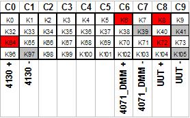
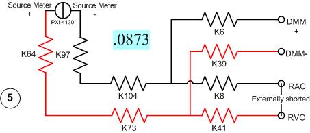
All I have changed is routing between the meter from the source. Here's the view from the matrix...
With this measure I'm mesure.0873 ohms. I can have the same resistance as the first example except getting a very different measure.
It gets even more interesting. If I had to take 4 pairs of wires, I use here, there are 16 possible configurations. I took each of these measures, and half of them gave me environ.25 ohms while the other half gave me environ.09 ohms. I tried this on a 2nd chassis and got the same result. My data are in the attached sheet. (My examples above are rows 1 & 5.)
Taking the measure of how we are, all these measures should be substantially the same. I have a current source constant, (I even tried a crimp in instead of the 4130 and got the same result.) and the meter is high impedance. If I had a pattern for the PXI-2530, I could do a little more analysis to know why I get various measures. Is there some diodes clamp on the lines or columns in the matrix? Something external must act solange this circuit. If I can find out what that is, I could determine my resistance to relay to a quantifiable level of uncertainty.
Any help would be greatly appreciated.
Greg
It seems that I can't remove. The correct message was placed here...
Once again, my apologies for the incorrect positioning of the post.
-
GPIB coding for HP4191A impedance Analyzer
Hello world
I try to use Labview as a HP4191A impedance Analyzer make some measurements of the base frequency. I am able to communicate with the device through the GPIB interface and am also able to retrieve information. However, I cannot successfully carry out a sweep or even to move the marker to measure so that I can read the impedance/phase information at frequencies other than the default game on the instrument at the time I perform the measurement.
Because the 4191 is so old, I've got my code manual programming for the HP4291A GPIB, which is supposed to be compatible with the 4191A. I suspect that this difference might be cause my problems.
In particular, after the implementation and launch of the instrument, I am initiating the measure and it reads as follows:
'INIT ';
' DISP:TRAC:MARK:ALL
 TAT. »
"CALC: EVAL: Y1:XPOS 300 MHz;
"CALC: EVAL: Y1
 ATA?;"
that comes straight from the manual of programming. In the code above, 300 MHz is an arbitrary frequency. However, rather than be sent back data at 300 MHz, I returned the data how the parser is currently set at.
If someone has worked with the 4191A and/or the front GPIB, can you check if my GPIB strings are valid or not?
Thank you
Matt
I worked with the 4191A and, if I remember, orders are nothing like any other tool I've seen. You really need the manual. I think the 4291 would probably take the old 4191 commands, but ALSO of new orders has the 4291.
IIRC, the scan settings have been something like this:
A = (start freq)
B =(stop freq)
C = (size not?) or was - the number of reputation points?)
Good luck with it...
-
By chance, we can know the reactance of the NI 5752?
Thank you.
Hey aka.
After my research we characterize the reactance so if you need determine this property, then you will need characterize it yourself. We characterize only the impedance to be 100 ohms. Hope this helps Alias!
Best,
-
PXI-6704, parallel to the measurement of the resistance
Hello
I'm in show two separate circuit analysis procedures. First of all I would like to provide two pins with current and measure the response of circuit elsewhere, and second, I want to test the total resistance not fueled between those two pins. If I have a current PXI-6704 output wired to the pair of pins and the value 0 output amp, it will interfere with the measure of resistance to these pins (as a parallel resistance) or if it excludes all signals and appear as an open circuit?
I can use the PXI switch to connect and disconnect the DMM to measure, but test specifications require no supply current through the switch.
I don't have the equipment to hand, I know it would be the fastest test. We design the test set-up circuit in parallel with the PXI test chassis.
Thank you
Mello
Hey Mello,
Thus, the output impedance of your card is 1GOhm, so unless what you measure is huge, so it should appear as an open circuit. I hope this helps!
Maybe you are looking for
-
How to get to the settings, DATA from the old HARD drive to new Tecra A10
My 'old' TECRA A2"refused to fly (fell on the desk)... Screen and grapfic external duty!But the HARD drive is still OK and works via an external USB HD adapter to my other PC. Can read all the files in the root directory,* can NOT read only password
-
Hello.. I just the iPad pro and smart keyboard. How to use speech as input device to in, say, Facebook or other applications where the microphone would normally appear (it is not, but should to the left of the space bar). Is it to do with Spart keyb
-
How to work the reentrant uninitialized in VI shift registers
-
report time for each process of VI
How can I know the big time consumig part of my VI in other words can I do something I would like to know how long each party in my VI took? Thank you
-
HP Pavilion dm3: internal battery dm3
to get the message that my 601 internal battery will need to be replaced... with the age of my laptop, it may be more cost-effective to get a new computer... If the internal battery goes down, will be the mobile service when it is connected to an ext