transconductance amplifier and analog output
Hello everyone,
Sorry if I asked a perhaps trivial question, but I'm still a beginner in data acquisition.
I need a negative pulsating current my PCI 6251 and measure the resulting voltage on the load output at the same time.
To do this, I thought about the exit a pulsed voltage AO0, sending voltage to a transconductance amplifier and generate a current in my care.
It is my transconductance amplifier... load, modeled on the square, is referred to as the + 5V on the PCI-6251 map and no 'field', since I need to be negative.
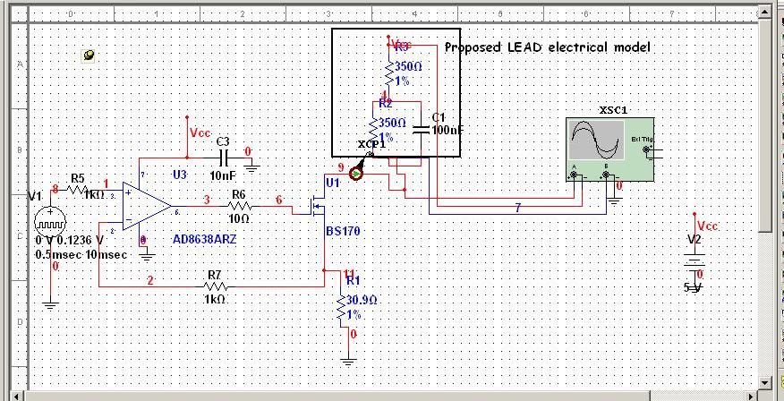
Now I have to read the voltage on the load through the AI0, and I lost between issues of land... Because the load is called my + 5V, should I measure differential or simple nerve?
Thanks for your time
Denise
Hi Denise,
You must acquire in differential mode.
See http://www.ni.com/pdf/manuals/371022k.pdf page 4-12
Ciao!
Tags: NI Hardware
Similar Questions
-
Using of FPGA VHDL IP and analog output
I use a system with Labview 2014 PXI. I've got Labview FPGA to program and run the card PXI-7854R.
I have the VHDL Code I want to use to control an analog output of the card. I use the IP integration node for this now but I also tried it making the process CLIP and still have not been successful. The problem that arises is that the IP integration node must be in a timed loop, while the analog output indicates that it cannot be put in a timed loop. Is there a way to provide an output of VHDL analog outputs of the card?
I tried to embed a loop timed within a while loop, but it still does not work.
I can't download the VI due to the policy of the company, but suppose I'm generating a sine wave in my VHDL code which must lead to the analog output of the card (the actual wave is company owner information but it is generated by a glance to the top of the table as a sine wave VHDL would be).
In an attempt to work the problem I retried import CLIP of the HDL code in a new project in Labview and VI. I'm still not sure about why it did not work with each other when I tried it.
For anyone who seeks to solve this problem:
I basically used this tutorial for the process CLIP: http://www.ni.com/tutorial/7444/en/
It also explains the differences between the CLAMP and the IP integration node.
-
To input analog shutdown when the analog output is completed and synchronization
Hello
I'm trying to get my LabVIEW program to send analog output to a computer and read acceleration using the cDAQ-9184. Chassis output that I use is the NI 9263 and the chassis of entry is the NI 9234. I generate a signal of white noise using LabVIEW Express signal generator.
The first problem I have is the synchronization. I had an old VI that has begun to measure the acceleration just about a second after the entry has been given to the machine. I used the LabVIEW tutorial on how to sync the analog input and output, only to discover that it does not work with two different hunts. Then I found another tutorial that shows how to synchronize different frames between them.
The second problem is the cessation of the LabVIEW program. What I want to do is to generate the signal and then simultaneously send and read the input and output analog, respectively. It is because I don't want a phase difference or any shorter signal for a direct comparison. But as soon as the signal is sent to the machine, I want the entry to stop analog playback and then then the LabVIEW program must stop. I want to be able to choose any length of signal to be generated and stop as soon as the entire duration of the signal has been sent to the machine.
I tried 'DAQmx stop', "DAQmx Timer" and 'DAQmx's task made?' and none of them have worked for me. It is also my first time on a forum posting, so I hope I gave enough information. I enclose my VI as well. The VI shows I read an entry for the analog input voltage, but I am only using this to try to get to the work programme.
I'd appreciate any help I could get.
Thanks in advance
Peter
Hi Peter,.
I have some recommendations for you that I think you will get closer to your solution. First of all, I assumed you meant that you had 1 chassis (cDAQ-9184) who had two modules in it (NOR-9263 and NOR-9234). My next steps are based on this assumption, so if it's wrong, please let me know.
For your first question about the synchronization, the code you provided is very close to what you need. You need to do, however, implement architecture master/slave for startup tasks DAQmx functions. To do this, you can add another frame to the flat sequence structure and put the master start task (input voltage) after the start slave (output voltage) task.
To manage your second question and that the program ends at the point where you, the first step is to get rid of all the logic that you use with the local variable of length of time. Rather than use this logic, just wire the node "task performed?" of "is task performed?" operate to stop the loop. This will cause your loop to stop as soon as the signal is sent to the machine.
I have some other recommendations for you that will increase the performance of your program:
(1) rather than writing on file inside the last loop, you can use the DAQmx Configure Logging (PDM) .vi. You will place this VI between DAQmx Timing.vi and DAQmx Start Task.vi to the task of the analog input voltage.
(2) after the last while loop, you want to stop the task and analog outputs as well with another DAQmx stop Task.vi.
(3) rather than using a local variable for the entrance of displacement and wiring it in the DAQmx Write.vi, you can wire directly from the output waveform of the wave to build function node.
That should help you get started in the synchronization of these tasks.
-Alex C.
Technical sales engineer
National Instruments
-
Questions about the synchronization between output and analog input
Hi all
I now have a simple task which head a signal voltage (from PXI ao0) on a circuit and then your comments a voltage at the terminals of a component, for example, that one of the resistors in the circuit, through ai0 on PXI. So in this case, the synchronization between analog input and analog output must be made to avoid error of phase shift.
I tried to build my VI by learning this example: https://decibel.ni.com/content/docs/DOC-3882
However I have a few questions.
1. I noticed that there is a merged error fed the "start task" sub VI for the analog output. What is the point of fusion to mistake?
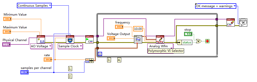
2. I enclose my VI (also shown below) for the output voltage. I put my writing of DAQmx Subvi in the while loop so that I can change the voltage while the VI is running.
However, in the example, the author has been reading outside of the loop and before even the start task. What difference will it make?
3. I have also attached my synchronized VI. I always put the wavegeneration and the DAQmxwrite in the loop. A bulging guard error saying about samples is not available and needs to a higher sampling rate or a longer wait time. What causes this?
I appreciate that these problems can be solved. Thanks to you all.
(1) first you need start the task of acquiring, he'll wait for trigger here. And then you start the build task that provides this trigger. If acquisition could trigger and never start.
(3) you must first write something in the buffer (writing DAQmx), then only you can generate it (Daqmx Start).
Check Cont Gen tension Wfm - Int Clk - no Regeneration.vi in the help-> examples for example.
-
Is a PCI-6120 card in a computer with linux useful for the analog output?
We have a PCI-6120, and we want to use in a computer with linux OS, to the analog inputs and analog outputs. I have downloaded the driver NOR-DAQmx Base 3.2 for linux, and in the file README.txt only analog input is mentioned for this Council. It is possible to use this card PCI-6120 in linux, with output and analog input computer?
Best regards
Hey, Gallas,.
This line in the README file simply refers to the PCI-6120 by its more popular, analog input subsystem (given that it is a simultaneous sampling device, the AI is the most commonly used subsystem). But NEITHER-DAQmx for Linux does not have the same limitations NOR-DAQmx base has. In other words, it supports the ability of analog output on the PCI-6120.
Kind regards
Sam
-
Synchronization of analog and digital output with the external sample clock
Hello
First of all sorry for my English, I will try to explain what I want to do.
I want my PCIe-6321 to send two custom signals (modification sawtooths) on a mirror controller. I would also like to generate output with my card at the beginning of each tooth of saw. Everything must be synchronized with an external k-clock signal of 100 kHz. The idea is that whenever the PCI receives a trigger to external clock, it sends two analog output voltages and when he received 1024 clock ticks it will also send a pic of triggering TTL. What I do is first prepare the map and after that in a loop sending and modifing the output values of the two signals and at the same time send a digital signal Boolean in each arch, so when's done it 1024 iterations of the loop I send an event to the digital port. Attached you can see.
The problem is that I don't know how to synchronize both. Can I use the sample clock just to the analog output? I can use sample for the two outputs clock, or do I need to use the output of the meter? If don't know how to use it here.
If I do nothing else bad/wrong, I would be grateful for feedback.
Thanks in advance,
PabloI don't know how but I find the solution. I'm generating more than a positive value (as I was triggered maybe very fast the oscilloscope has been absent there). If I put the sample clock of digital output to use the sampling/ao/Dev1 clock that it doesn't, but if I put to use the same source as the OD (terminal where my external clock is connected), but the trigger to start the DO to be Dev1/ao/StartTrigger this works. I don't really know why, but it does.
Thank you for your patience and your help. I put here the final code.
-
How can I pause and resume the analog output using DAQmx?
I use a DAQ hardware to produce an analog waveform. I would like simply to break the output of the wave and then resume where it left off. I use DAQmx and LabVIEW 2011.
I've seen examples that use a digital or analog break trigger, but I would take a break in the software only. How can I do this?
-Joe
Hi Joe!
I spent some time thinking about it and I realized that you can technically use a fundamental mission of the analog output, as you previously wrote that runs continuously. However, the generated output samples are controlled by the sample clock pulses, and can be manipulated to fit our needs "suspension."
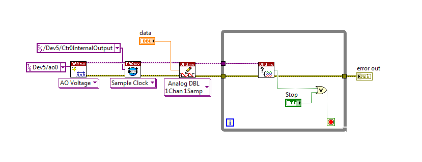
To do this, we will need another counter task that generates a pulse train (see our examples of shipping under material input and output > DAQmx > generating digital pulses > generate dig Pulse Train - Continuous.vi) that stops and starts the user to choose. This can be in another quite VI or controlled by software. We will use this as the task of our output sample clock.
Then, the task of the AO, wire a constant to the sample clock source and select ' DevX/CtrXInternalOutput"based on the counter that you specified in the task of counter. You will need to choose "I/o name of filtration" and check the box that says "include advanced terminals' and right-click of the constant. See picture attached as a reference. In this way, the task of the AO is constantly running, but it generates only actually all data when the meter running task.
Let me know if you have any questions!
Have a great day!
-
6009 outputs digital and analog input synchronization
Hello
I work in a program NI 6009. I want to leds by car with outputs digital NI 6009. For example, leads first will be on until what 200 micro seconds then second led will be on up to 200 micro seconds, and then first of all led will be on up to 200 micro seconds. I'll take led with photodedector signals and connect analog output photodedector input NI 6009. I want to synchronize the outputs digital and analog input and separate the first and second led signals the analog input for NI 6009 channel. How can you do with NI 6009? Please ADV
You can not do with the USB-6009 case. Its outputs digital are software with a maximum speed of slightly more than 100 samples per second. The outputs can produce 200 microsecond pulses and cannot be synchronized with the analog input.
You need a device with outputs digital hardware timed or counters that can produce a pulse outputs.
You can synchronize a bit digital output and analog input recording signal on an additional channel to HAVE. Will allow you to see the photodetector and LED the drive with the same schedule and such resolution as described by the sampling rate I. The maximum sampling frequency of AI on the USB-6009 case is 48 kHz that is shared by all channels. If you have two lights to led and photodetector two signals maximum sampling rate would be 48 kHz/4 = 6 kHz which is barely fast enough for your 200 US signals. For more than 4 channels, it won't be fast enough.
I suggest a simple oscillator circuit building and use it to clock a flip flop. This will give you alternating signals to drive the LEDs. You can use a line to reset the flip flop to give you control without the need for high speed.
Lynn
-
connect the sensor (0-5V analog output and 9-28Vcc power) to NI 9219
I m chemical student here. And I'm not trying on the measurement of the pressure.
I have a pressure sensor with the specification of 0 to 5 Vdc analog outputs and power supply 9-28Vcc. And I intend to plug the connector which can be used for the NI 9219 (4 analog input). Therefore, there are 6 terminals and I have to choose the correct mode voltage (which is the terminal 1, 2, 4 and 5 which will be used), is?
So there are four wires for my sensor connector:
Red: power supply (+)
Black: Return supply (-)
White: Output 0 to 5V
Green: output
Therefore, how to connect these wires to the national instrument?
Looking forward to you guys.
Thank you.
Best regards
David
Hey David,
My previous suggestion is wrong, it's good.
Red (pressure sensor) = + power supply
Black (pressure sensor) = - power
Green (pressure sensor) = Hi, pin 4 (9219)
White (pressure sensor) = Lo, pin 5 (9219)
Sincerely,
Krisna
-
Strange problem with analog output PCI 6251 and BNC-2110
I'm controlling current source of third parties using the connectors of analog output on my card PCI 6251 and BNC-2110.
The current source needs an input signal of 0.1V. I tested it using a battery, the potentiometer and the voltmeter, and by manually adjusting the voltage of power current works - current output with control voltage scales according to the specifications and is relatively stable.
The data acquisition card works too - when I connect a voltmeter to the AO0 AO1, the measured voltage corresponds to the target with great precision value.
But when I connect the current source of third AO0 AO1 data acquisition card, the measured output voltage drops and fluctuates. This applies to both channels of the AO.
I wonder what is the problem here. I suspect it could be a matter of the grounding - the current analog control of the source is an entry with two floating terminals differential. I tried to return the switches FS/GS on the BNC-2110, but that makes no difference.
Anyone knows similar behavior? Does anyone have any suggestions?
-
How to write constantly to analog output and read from analog inputs
Hi all -
I had a question about writing continuously to analog output reading simultaneously an analog input.
It's my first time to post a message to the community, so please let me know if I made mistakes.
I use Labview 2011 with a NEITHER-DAQ USB 6215.
I'm looking to generate a waveform and write it continuously in an analog output. It is then connected to an entry on the acquisition of data, where I am trying to sample the analog signal. (I realize, there is a system of trivial, but I'm hoping to build on it once I have run).
The task of reading from the analog input works fine, as I tested it in several other cases. I have a problem writing to the analog output.
For this task, I tried to follow the "Gen Cont Wfm Clck Int' VI to generate the wave form and start the task. I then try to write to the output of the analog timed loop. However, it does not seem to transmit a signal and doesn't give me any errors.
I have attached the VI but also a screenshot.
Please let me know if anyone has any ideas. I would really appreciate the help!
Thank you
Peter Borgstrom
We will review your tasks one at a time. First of all, the task of generation/Analog output Waveform. Generate you a waveform (I'm unsure of your VI if it is a fixed waveform or not) and send it to a defined output function to produce a waveform continuously, using N-channel and samples of N (where you set not these previously). You should not put this inside has timed loop, as the DAQ hardware has its own clock - if you simply put it in a while loop (with a stop to break out of the loop), the loop will call the function for the first points of N, wait until all N have been taken out, then call it again to another N points (up to what you press Stop).
Now, suppose that you have the output connected to a load voltage (say a decent resistance). You can wire the input terminals of your A/D converter through the same load and set up a similar analog input loop, running in parallel (i.e. in its own independent of the OD loop, while loop). You pourriez start together (with, say, a merged error since the initialization code line loops HAVE and AO become lines of error in "loops of sampling" described above), but you might want to delay loop (a little) the AI so that the OD has a chance to set the voltage before the bed.
I hope this helps.
BS
-
LabVIEW 7.1 Analog Output is incorrect, computer crashes and often generating output resignations
Try to put in place an old pc with Labview 7.1 NT with an AT-MIO-16 x card... everything is loaded, I can load OR-DAQ 6.1 examples and Configuration DAQ ESPECIALLY utility works correctly.
In the config utility, I can put all the settings are correct, but I get the dreaded "the device does not respond to the first IRQ setting" for all the IRQ numbers acceptable that I choose 7,9,10,11 as 5, or 15. Others are simply not available, and all those who are to generate the same message. However I can run the test panels and get an analog output, for example, fine, tested with an LED.
So I moved upward to load an example VI, the function generator... Sort of works, it breaks easily, or stops, generating a total, if I hit the stop button and restart, and its output looks nothing like one of the square, etc. in sawtooth, sinusoid, shapes, watching on a scope, it is just hard hitting high then low, sometimes spitting a gust of sinusoid for half a second or so.
I suspect this is related to the issuance of the IRQ, I searched all knowledge bases, come up with nothing that solves this problem. Thought maybe someone could lend an idea. LabVIEW is really more stable than this right?
Well I've tried a bunch of things and success. Looks like my MIO Board is kaputt. Good thing I have 3 of the guys. The other set up fine in config and short decent for the torque screw daq example I tried.
Continuation and thank you very much for answering.
-
the time of acquisition of data - how to calculate the rate of analog output
I want to calculate an acceptable rate of analog output, one that is taken in charge by material (PCIe6353), without the rate being changed by the VI DAQmx Timing (sample clock). The final objective is to have a rate of analog output that is an integer multiple of the analog input for precise frequency, since the sinusoid AO's amplifiers, which have a ringtone when AO updates occur.
According to 27R8Q3YF of the knowledge base: how the actual scanning speed is determined when I specify the rate of scanning to My d..., the rate is revised as needed by calculating the rate of clock / asked for advice, divide the result rounded downwards and upwards in the clock of the Board and use the one that is closest to the requested speed.
If 'Embedded clock' is selected, which is the result "Council clock. DAQmx sample clock timebase Timing node - SampClk.Timebase.Rate says 100 ms/s. However, for a rate resulting from the update of 2.38095MS / s, the divisor of the time base timing node - "SampClk.TimebaseDiv" gives a value of 42. 42 x 2.38095 M = 99, 999, 990, where it should be 100 ms/s.
How to calculate an acceptable rate of analog output is supported by the hardware? I have other plates, in addition, a general method would be appreciated.
I haven't worked all the details yet but noticed a few things that may be relevant.
Req AI rate isn't a whole ditch 1E8. It is used to determine the rate of the AO.
There is no check to ensure that the rate of the AO is an integer division.
It seems that you have the right idea, but the implementation is not yet there.
Lynn
-
Problem when the PWM signal combinning and analog signal TOGETHER!
Hello everyone,
first I DAQmx 6212, and I need to run the water pump small (9V - 16V) that should be driven by a PWM signal; I also have a motor (5V - 13V) for a water supply which must be controlled by an analog signal and it has built in a force feedback potentiometer, I logged onto this potentiometer correction + 5V the DAQmx and used the output voltage of the third extremety as a value to diagnose to know the position of the engine.
My VI shows:
1 is a normal meter production to create my PWMout signal.
2 is an analog input, I use it as a PWMin to the LabVIEW to diagnose what is happenning in my pump water through the cycle and frequency.
3 is an entry of the third extremety of the analog potentiometer.
4 is an analog output that I used as power supply of the motor valve and I used an AC/DC amplifier for aplify signal the DAQmx and the motor road, between the two (3. 4.) I made a comeback with a few calculations, I had a P-controller to know the real position of the engine valve.
My problem:
When setting to 1. and 2. in the same VI only, I get an own PWM output with no problem.
also with 3. and 4. in the same VI only i can control the motor valve without any problem.
but when I put all these 4 set found in the attached VI, I have a problem as the engine valve turn continuously without stopping even if I change the position of the valve between 0 and 100%, I should mention that I see a PWM normal outside a signal on my oscilloscope, another thing to delete one of (1 or 2) and run the engine valve VI works fine without any problems.
so this my problem, if you can think of any solution please let me know.
Thanks in advance for your help.
Kind regards
Caliente
Here's your VI, slightly modified so the two analog inputs belong to the same task. This if only for purposes of illustration, I him have not tested. You will still need to do some debugging.
While changing your VI, I noticed another potential problem with your original configuration. You have configured the two tasks of AI for the same frequency, but read you 10000 samples of one of them and only 100 samples from the other (and throw it most of it). Data acquisition data are buffered, and if you read as fast as you acquire, the buffer fills eventually. If you read 10,000 samples of a channel, and the other channel acquires at the same rate, then when you read from the second channel you will get old stale data or an error full buffer.
-
Portege M400: Port Replicator support DVI and analog monitor
Hello
I use my Toshiba M400 in the duplicator.
The duplicator has two outputs to a DVI and an external analog output display.I would use both screens at the same time under Windows Vista RC1.
The port replicator manual mentions that this should be possible depending on the connected computer."According to the computer connected to the port replicator, you can connect external monitors to DVI port and the port external monitor and display on both screens at the same time."
Someone he knows the M400 which supports? I only get the external DVI monitor or at work.
(He used to work with my old others and this function was just great).A big thank you in advance.
Rogier
Hello
I'm not sure but pretty sure you cannot connect two external displays at the same time due to the restriction of graphics card for laptop to 100%. You can stretch relative to your office for two screens (one internal and external) or have the same image on laptop LCD and external TFT connected DVI or RGB port.
If I read the sentence you have posted I realized you can use two ports (according to specifications) and use two screens on the same time screens (laptop screen and an external).
All available modes to switch the display to the external one, you can check with the combination of keys FN + F5 or in change of display tab tool mobile extension of Toshiba Service.
Maybe you are looking for
-
iTunes and app store menu missing from missing settings after put 9.3 updated ios (iphone 6)
Today, that I update my iPhone to iOS 9.3 6. I noticed that itunes and App Store menu missing from missing settings after (usually presents below iCloud) Is anyone else having same issue?
-
HP Pavilion dm4 - 3013cl: replacing hard drive
This laptop doesn't have a hard drive or Ram access doors. Basic coverage is full size. How open to change a hard drive?
-
Problems with the resource of labview execution 2 visa
I use two loops in a labview code all-in - connects to a motor controller and other is used to connect to a multimeter agilent. As soon as I run this VI, the loop to connect to the controller stop working and only used to configure agilent machine wo
-
My OS is Windows XP Pro SP3 and when I bought my computer in 2004 he had these drivers for xp pro. I want to know if I can update the drivers to the latest versions for XP Pro SP3?
-
Error 7 (Windows error 193) windows xp
What is the error correction protocol 7 (Windows error 193) for windows xp I only find answers for vista Candace