TTL-Switch
Hello everyone,
I have a question about a "Digital-Switch" I need for my work.
Is it possible to create a TTl-switch using a digital output and an analog or digital input channel?
The idea is to generate a constant 'High' on the digital output and to measure the high or low, depending on the State of the switch, with an analog or digital input.
I have attaced a drawing to highlight what I mean.
Risk damage to equipment if I use this circuit?
Greetings
Okay, I think I got it.
Thank you very much for your help!
Tags: NI Hardware
Similar Questions
-
How to switch between 0 v and 5 v using the FTDI USB-to-TTL converter?
I have one of these (TTL-232R-5V-WE) FTDI (http://www.ftdichip.com/Products/Cables/USBTTLSerial.htm) and it came with a few screws to control the USB converter.
However, I do not know how to exit (between Vcc and Gnd) 5V to 0V.
Basically, what I need is alternation since the converter FTDI TTL signal output.
Any help please? Thank you in advance.
Hi sclow,
the link provided, you will find data sheets with all the necessary information. This device implements a COM port that is usual with just TTL level signals. The SCR will always provide + 5V with no opption put. But we can use the CTS/RTS signals! Just look at the description of the node property VISA-> settings-> modem line parameters series...
-
several finite pulse trains of TTL
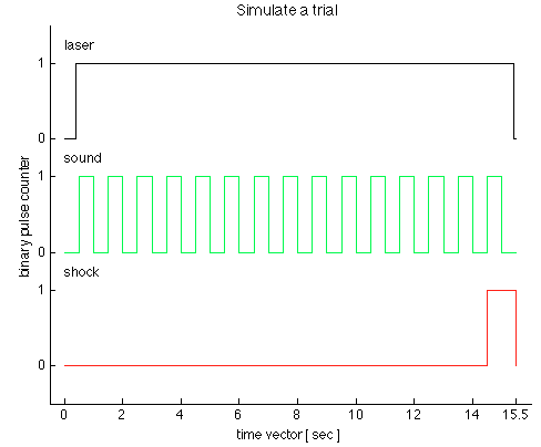
Dear members of the forum OR,.
We have just received a chassis NI SMU-1073 with an SMU-6361 OR switched in PXI1Slot2 and a shielded connector BNC-2111. Aims to generate trains of three TTL pulses to control a laser, sound and shock via Matlab Application. I use the C OR-DAQmx API with Matlab MEX to integrate C in Matlab code.
I came up with the following code in the examples in C to generate a pulse over TTL time-based train:
initialDelay float64;
float64 lowTime;
float64 highTime;
uInt64 periodsPerTrain;
float64 taskMaxTime = (lowTime + highTime) * periodsPerTrain + 2 * initialDelay;Configure Pulse
DAQmxErrChk (DAQmxCreateTask ("", & taskHandle));
DAQmxErrChk (DAQmxCreateCOPulseChanTime (taskHandle, "PXI1Slot2/ctr0","", DAQmx_Val_Seconds, DAQmx_Val_Low, initialDelay, lowTime, highTime));Configure the Pulse Train
DAQmxErrChk (DAQmxCfgImplicitTiming (taskHandle, DAQmx_Val_FiniteSamps, periodsPerTrain));Departure Train
DAQmxErrChk (DAQmxStartTask (taskHandle));Wait for execution
DAQmxErrChk (DAQmxWaitUntilTaskDone (taskHandle, taskMaxTime));Clean
DAQmxStopTask (taskHandle);
DAQmxClearTask (taskHandle);I'm stuck with two problems:
1.) SMU-6361 has 4 meter signals ctr0-3. With the above code, I can generate separate tasks for each TTL signal and evoke them consecutively with DAQmxStartTask. But in this case, I guess that the tasks are not synchronized. Can I use the clock signal to synchronize the other 3, for the tasks of each is triggered at the same time? What will be the right way to do this with the C API? The step of the smallest of the discrete-time in the example is 500ms. see the picture as an attachment to check how the TTL signals should look like.
(2.) what is my physical connector on the BNC2111 to outsource these signals.
/ PXI1Slot2 / ctr0-> PFI12/P2.4
/ PXI1Slot2 / ctr1-> PFI13/P1.0
But what ctr2 and ctr3? How can I configure the physical connector outsource? Is there a function to specify that?
Thank you in advance for any advice, suggestions and directions!
see you soon,
go9kata
Hello go9kata,
for your second question, with the BNC-2111. You can route the signal from the counter for
lines PFI avialable on the block of connection BNC 2111 with the following syntax
DAQmxErrChk (DAQmxSetCOPulseTerm(taskHandle,"/Dev1/PFI0"));
I hope that helps, if not please let me know.
-
digital output usb6009 does not switch does not correctly
Hello
I have a little problem with my 6009.
Basically, I switch the inputs of a Demux (74HC238D) (3 lines) write an address on it to select rows of data off the Demux.
The signal from the acquisition of data through an FPGA and the signal is displayed on the input pins Demux. That is the problem.
(It is worth noting that the FPGA is well programmed (coz if it was'nt then the signal would not get the demux in the first place.))
When I connect the inputs of the FPGA to 3 digital lines of data acquisition and scroll lines (turning each one WE and OFF), the signal appearing at the Demux pins is not a proper logic level. (the voltage I measured the scope is about. less than 1.1 V). For this reason I choose any line, Demux output will always be on the first channel and will not select the other channel.
I tried the same test 7 connect supply of 5V data acquisition (each line) and after having programmed the FPGA, the correct voltage level is available on the DEMUX pins. The problem occurs when I try to scroll through the entries via the software.
I'm not which is the cause. My belief is the acquisition of data.
What are your suggestions?
Thank you
Labmat
Hi Labmat,
The first thing that jumps out to me is the fact that you use these signals to interface with an FPGA. Outputs digital USB-6009 are 5V or 3.3V TTL and commonly FPGA i/o is 3.3V. Just to double-check, as FPGA did you use?
Q: When I connect the inputs of the FPGA to 3 digital lines of data acquisition and scroll lines (turning each one WE and OFF), the signal appearing at the Demux pins is not a proper logic level. (the voltage I measured the scope is about. less than 1.1 V). I tried the same test 7 connect supply of 5V data acquisition (each line) and after having programmed the FPGA, the correct voltage level is available on the DEMUX pins. The problem occurs when I try to scroll through the entries via the software.
A: This no doubt hits the nail on the head. First of all, I'd be inclined to not use program any software directly and instead use some of the tools for debugging I/O connectivity that come with the Driver NOR-DAQmx. You can get these from the measurement and Automation Explorer (MAX).
' ' ' ' 'Start-up' all programs ' National Instruments ' measurement and automation.
Expand the tree of devices and Interfaces in the left pane, and then select your USB-6009. Using the Test panels button on the right pane, you can quickly perform digital i/o with the device.
Our best bet is to first take a multimeter and see if we can measure the correct voltage is distributed by the correct pins on the USB-6009 case.
Now, by checking the box USB-6009 Datasheet, we can see that, on Page 17, there are a couple of different ways that we can configure the method by which the output signal is driven out of the unit; We have Drive open and active collector mode. It will assure you that since you are trying to send a signal to the FPGA, the unit must be set to active training mode, in order to generate signals from 0V to 3.3V . Output open collector allows the generation of signals from 0V to 5V . This can be done through property OR DAQmx nodes in LabVIEW.
In terms of current...
The + 5V line that you used for the FPGA Nailer is evaluated to 200 my. General DIO lines on the USB-6009 case can generate a current up to 8.5mA. This limitation fits the specifications of digital input of your FPGA?
-
Handshaking DMM with multiple switching devices - DAQmx error
Hello.
I am trying to create a loop of the handshake with DMM (PXI-4071), SWITCH (PXI-2569) and MUX (PXI-2575). The three instruments are in segment 2 chassis PXI-1045 (locations, 8, 9 and 10) and I use the ways of PXI trigger in the triggers of the route.
I followed the article NOR 'Multimodule Scanning with National Instruments switches' - I modified the example NI SWITCH "niSwitchDMMSwitchHandshaking" to set up another SWITCH, but when I tried to run the example, I got an error:
0xbffa6b9a - no lines recorded could be found between the device in the road. (screenshot pop up is in the attachment). It is the function of niSwitch_InitiateScan to the second switch that returned an error.PIX trigger change has no effect.
I tried the CVI and LabVIEW examples with the same result.
I even tried to use two 2575 MUXes - same result.Can someone tell me what I am doing wrong?
Hi Pavel,
I checked that the component that controls the routing of the TTL for the PXI is included in NOR-DMM 3.0.2 (latest version as of 06/14/2010). NOR-DMM 3.0.1 contains an older version of the TTL routing code and will therefore place several comprehensive lines scanning advanced on the same trigger.
Unfortunately, the component which controls TTL routing is one of the constituent elements of the software installed OR lower, and thus we do not expose it to the user. For that to work, we would need to uninstall almost all the software components of NOR, which is a major undertaking. Here's what I recommend instead:
For now, we will Garland triggers one switch to another. This will allow us to start development in OR-Switch; as soon as OR distributes a program, you simply change the triggers as they all point to the same TTL line. This will allow switches to operate in parallel rather than in series, and the passage of the switch of your project can run faster.
If we have to absolutely exploit the switches at the same time, I would recommend either uninstall all software of OR or get a machine with a fresh install of XP and then install not newer than 8.9.5, OR DMM 3.0.1 DAQmx software and NI - Switch3.8.
As I mentioned earlier, NEITHER is aware of breaking backward compatibility and we are committed to reintroduce the old features in a future release of the pilot.
Keep this thread bookmark and post back in a month or two and I'll let you know if we have any updates.
Have a great day!
-
How to generate a continuous ttl signal with a USB-6501
Hello everyone,
I am a beginner with LabView, so maybe my problem, it's very easy to fix.
I need to generate a digital output using a USB-6501. This TTL signal will then switch to a device. Basically, I need the digital output to be permanently to TTL high level until a user active departure is given. Then the digital output must stay to the TTL low level until another stop active user is given.
Does anyone have any suggestions on how to do? I have failed so far to get something different high TTL to my USB 6501.
Thank you very much.
Hi there, take a look at the VI I enclose. You can find more information about the device in textbooks and on this forum. I hope this helps
-
Hello everyone,
I am puzzled about the problem I've encountered in my vi. It's acquisition of forces from a load cell and he recorded the coordinates of the point of my motion system.
I added a block to trigger, which sends the TTL 5V signal to a PIV system, trigger works, and I can read signal meter and PIV starts its sequence after him. What I am tryint to accomplish is to start recording to the file and trigger at the same time.
I tried to bulean my "writing on a file" control switch wire to digital bool > slot, but when I run vi, as soon as I press "record", labview freezes. If I create a bulean dedicated control for relaxation (which is what I have in attached file), everything works fine.
Can someone proposes a possible solution?
Thanks in advance
Oleks
Update,
I found the problem. Apparently, I have to pay attention to the error message. The cause for the program of 'freeze' was my attempts to write data in a switched to the broad external hard drive... Ouch
It's working now.
Oleks
-
Required NI 6132 TTL interface buffer circuit?
Hello
I use a NOR-6132 for my research project. I use it on Linux with Python scripts wrapped around the C API for DAQmx. I programmed successfully map to the output of a signal (baseband code Manchester, waves so basically square with 4.7us pulse width), founded the digital output port. I enclose parts of the code that I use:
dsamplerate = 2500000.0
SampleSize = 24digital_output_str = r ' Dev1/port0/line6.
DoTask = nidaqmx. DigitalOutputTask()
DoTask.create_channel (digital_output_str, name = "line5")
DoTask.configure_timing_sample_clock(source=r'ai/Sampleclock',active_edge='rising',rate=dsamplerate,sample_mode='finite',samples_per_channel)DoTask.Write (ddata auto_start = False), layout = 'group_by_channel'
raw_input ("Press ENTER to start writing")
DoTask.Start)The problem I face, is that even if the output is supposed to be digital (TTL), I get some distortion/waving appearing at the begginning of my square pulses. The card allows to switch out of 0 v to 5 v + - a certain ripple and then settle down to how it should be. I test by connecting the output of my card at the same time an oscilloscope with impedance of 10 MB and the analog inputs of the map by simultanteous output digital and analog input. You can see the result on the field of application in the attached picture, shown in blue. Due to the division of time into the particular image it shows as a pic, but if I drop it it would show like a ripple.
I don't think it's a sample or a sample size problem because I tried with the lowest and highest in sample size sampling rate and I always ge ripple even. TTL at the end of the day should be high or low, if there are 1 million samples or just 1 sample.
My question is, by looking at the technical details of the card it says I has a bias of 50KOhm could need, with traction sense Pu. Do I need to use a resistor pull-up to the output of the card? What I need to design an ampliifer buffer to match the output port Digital card in the equipment, I will use? My intention is to connect the digital output of the card to an analog modulator and mix it with a subcarrier from a signal generator (analog signal). The impedance of the modulator is 50Ohms.
Thanks for looking at my question.
Hi Matthew
Thanks a lot for your comments. I use two sons of strong base, welded on a BNC connector. A single cable is connected to the digital earth and the other P0.6 digital line and the other end to the scope. I don't see the Spike on the skope. When I pick up this signal with the analog input of the card, the result is smooth, you can see that I join you on the graph in the middle in the new image. If I generate a TTL with the same frequency and the votlage level with my generator to function if the scope has no problem to catch him without the points. He has only problems with the TTL card is outputing, but here again the analog input of the card has no problems with the same connection cable. I can only assume that there is a level of ability between the map and the scope, I have no other explanation as to why the stars appear on the scope.
Thank you for your time.
-
Hello everyone,
I try to start acquiring the image of a TTL pulse generated in Labview (PIV). I have a TTL signal (I hope it's TTL) generated through devices to the switch to zero of a periodic signal, type sinewave 1.42 Hz [I use PXI 6221 Council with SC-2345 (with FT01 connected to the BNC port), TTL comes of the FT01].
After connecting to the input TTL trigger, the amplitude of the voltage is 5V to 4.77V falls. The trigger seems to work occasionally, but not always. I contacted the company that we provided the image acquisition hardware/software and they mentioned that TTL [(0-5 V onde carrée)] must be at least 5 Hz. This confuses me a little because I don't really know how to control the TTL frequency and if my code can accommodate for this and I'm starting to doubt my code as well.
I have attached my code for reference, if anyone can give me a hand I would really appreciate it.
Thanks in advance!
Alex
Oleks,
There are a few things that need to be changed. First of all, your task of counter, you enter in the while loop and check if something is true or false. If it's wrong you stop the task, but in the case of true you never repeat the task. You will need to start the job in the State to resume. In addition, you will want to place a control task.vi DAQmx after schedule vi and set it to commit. This will ensure that your task running as soon as possible after the judgment of the task it with no re - check all data before running again.
-Travis E
-
Reading USB-6210 tension slowly decreases with switch
I am able to output constant 5V to an adapter hung on the wall. The positive wire goes through a switch to the positive terminal AI and the negative wire goes directly to the corresponding terminal negative AI (basically I want the analog voltage to reflect when the switch is on or off). I have the DAQmx configuration for differential configuration. When the switch is activated, it reflects 5V quickly, however when the switch deactivates the voltage goes down very slowly, taking 30 seconds or more to bottom. Also, it does not on 0V, she settled on approximately - 600mV or.
My configuration configuration is incorrect?
Also when I connect a multimeter to the circuit the DAQ steps perfectly, with the tension fall closed when the switch is opened. So maybe the configuration is correct and the introduced impedance is what it takes?
Andrew:
Your train is correct. 6210 has an input impedance of 10Gohms, so, when you open the switch, the factor of the resitance/capacimetres will take much time to bleed pressure down and the entry of data now being an open circuit, it can float just about any level of tension. You could put an arbitrary ristance between terminals of input data acquisition (but not too low). Try something like 10K or 100K ohms.
Alternatively, you can use one of the digital inputs on the 6210 to monitor the switch. Given that supply is 5V, it is compatible for the TTL inputs.
-AK2DM
-
I'm looking to deploy a series 5100 Cisco NEXUS switch at 10 Gbps.
I know that the Nexus is supposed to work with the converged network adapter (for 10 Gbps FCoE, etc.), but can it operate without an ANC?
I want to put some passthrough 10 Gbps modules in my Dell m1000 chassis and the cables directly to the Nexus switch.
I know that the Nexus is perhaps overstated for this solution, but it is a step in the UCS solution for us.
Thoughts?
James
Hi, you don't need special drivers for "low latency" 10 Gbit ethernet on a 5 k.
for example, to switch non-nexus 5 k
PING 10.10.10.1 (10.10.10.1) 56 (84) bytes of data.
64 bytes of 10.10.10.1: icmp_seq = 1 ttl = 255 time = 0,530 ms
64 bytes of 10.10.10.1: icmp_seq = 2 ttl = 255 time = 0.618 ms
and a nexus 5000 with a qlogic 8152
PING 172.16.78.3 (172.16.78.3) 56 (84) bytes of data.
64 bytes from 172.16.78.3: icmp_seq = 1 ttl = 128 time = 0.150 ms
64 bytes from 172.16.78.3: icmp_seq = 2 ttl = 128 time = 0,134 ms
Oracle rac cluster will fly!
-
House-keeping FRO automatic function TTL (time life)
We often store data in our KVStore which must remain only for a limited time. Our current solution is to follow the "expiration date" in the data itself and have a household job regularly to purge the data. I wonder if one sort of TTL (time life) can be added as meta-information for each entry with automatic purge running processes.
That would make sense? Or maybe, is there another way rather than to specify an expiration date in the data itself?
Hello
In fact a TTL feature is being developed and is included in a NoSQL DB to come free. I suggest that you continue to use your current approach until the TTL feature is available and then switch to him to improve performance.
-mark
-
Buzz of noise in the tempo switch
My song has 4 different tempos. Every time that happens, occurs a humming noise. If I get all tracks FX behind it disappears. How can I keep the delay, but not the buzz?
Thank you y´all.
Use automation for on/off switch of the delays to and after each change of tempo.
If that kills too late in the face of that time, and then introduce a Gain ahead of every delay, automate the Gain to cut admission to the delay when changing the tempo. Who will cut the whole track, however.
-
Switch between keyboard languages 3 (or more)
I have three languages: language A, language B, C language
I'm on A language and to switch to the C language.
Heat the shortcut keyboard CMD + space twice to change the language. It's change of a language.
I have heat twice again and it works properly.
How to disable this smart switching algorithm?
You really tell us that what you see in the menu 'flag' on the top right of the screen does not always match what is typing at the keyboard?
-
Can I switch to OSX 10.9.5 directly to Sierra.
Can I switch to Sierra de OSX 10.9.5 no other updates between the two? I have an iMac mid-2011.
Yes.
(145115)
Maybe you are looking for
-
Retitle of books for the sony PRS - T1 E
I bought this tablet problem and having, when importing books. Titles of the books are automatically renamed in my player. How is it possible to rename the books yourself, because I can't find this option in my ebook reader.
-
USB DAQ error after update to 15.1 DAQ
Everything worked well (DAQ 9.5) on my windows XP SP3 machine, so I thought that it's a good idea to install the last DQA 15.1, NOW my USB DAQ has a Red Cross in NI MAX and does not I tried to reinstall OR DAQ 15.1, restarted the PC, plug the NIDAQ i
-
battery CMOS does not start after uninstall "Neverwinter Nights"
While start-up after uninstalling "Neverwinter Nights" I get CMOSbattery failure, please press ENTER to continue... How can I remove this warnig and go straight to the office?
-
Windows 7 can not get the KB971033 update to install
CAN'T UPDATE KB971033
-
HP Photosmart C4680: HP Photosmart C4680 driver for Windows Vista 32-bit
I can't find the HP Photosmart 4680 for Windows Vista 32-bit driver. The HP Web site has only the driver for Windows 7 and newer. I tried to install this driver, and obviously it did not work. Can anyone help? Thanks in advance.