Type of output USB 6501 digital IO
Hi, I'm new to this software.
I use an e/s digital NI USB-6501 24 lines.
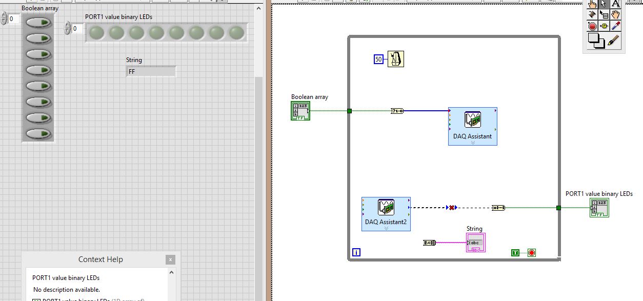
I physically wired PIN0.7:0 to PIN1.7:0, then all PORT0 go to PORT1
Click these buttons to table of Boolean, to set the output levels of PORT0, then having the signal wires to PORT1, which is then set accordingly, and then I want to ouput PORT1 using DAQ Assistant2 in:
(1) an array of Boolean LED
(2) a string indicating the value of the port in hexadecimal.
THE PROBLEM:
The DAQ Assistant2 outgoing data type is "table 1 d to unsigned long. The entry of the table that should receive it is "1-d array of boolean.
So, there is a data type mismatch.
How can I make this work? As you can see, I tried to place converters, I tried several converters, but I don't know what to do. Advice?
Stupid DAQ Assistant. I have no idea what is thinking want to a table. Personally, I just use the real DAQmx API. At least then you can say what is happening and it has less overhead.
A couple of other things:
You must move your controls and indicators for the acquisition of data inside the loop values. In this way they can be updated at each iteration of the loop.
Really, you must add a stop button. You need a way to cleanly stop your VI and do not use the button abandon in the toolbar.

Tags: NI Software
Similar Questions
-
NI USB-6501 digital output problem
Hello
I use DASYLab v.11 and I'm working on an interface with the NI USB-6501 where I'm putting a digital high on four ports.
With the module "NOR-DAQmx - digital input", I managed to read the digital inputs of the ' NI USB-6501 ".»
It's only the "NOR-DAQmx - digital output" I can't go to work.
Using 'NI MAX' of NOR I have easily can emmit my four LEDs in the way of my High/Low ports.
But not with DASYLab. When you use DASYLab tension on the ports remains unchanged.
Now, I have a switch module, generating 5/0, directly connected to the digital output module, which is assigned to my four output ports for my task.
I also tried with a module of relay between the two without success. I also tried to use 1.5 above instead of 5 without success.
I use the option 'Bus (0/5 supply) for the module "Digital output".
"NI Max", I configured the ports as "active drive.
Any suggestion of what I might be missing?
Thank you
Martin
Hmm, four ports, or four lines?
A port consists of eight lines. Each line can control an LED (ON / OFF ~ 0/5V).
If you have created a task to dig-out to control a port, 5V to this port sending sets all lines of this port to 'high '.
You need to 255 for each line one too high port (at the bit level: 128 + 64 + 32 + 16 + 8 + 4 + 2 + 1).<- eight="">
Or, you can create a dig out tasks to control four lines of a specific port.
Four lanes of the EEG DAQmx DigOut module.
Each of the channels of the modul will feed a single line of the task/device.
Four switches will then turn the lights, or turn off.
Make sure, that the 'bitposition' is the number of correct line (see picture).
-
USB 6525 6501 digital for output to the step motor
Hello
I try to use USB 6501 or USB-6525 out of step motor signals which command the stepper motor. My questions are
(1) do I 6525 USB, I'm not sure the function of it (perhaps as a relay).
(2) now I connected input 5V for USB-6501 "+ 5V" pin and GND to pin "GND". On the other side (output side), I connected ' enable '(from motor drive) to P0.0. 'direction' to P0.1 and GND to GND. Can I use the express signal to test, the error says "lack of entry."
(3) I guess the next step is programming labview. Does anyone know of similar examples?
Any help would be appreciated!
Melody,
If the engine must input external logic level I advise to use the USB-6501, which is just a digital I/o card. The USB-6525 housing does not have the digital outputs to control your motor drive. If I understand correctly you just try to turn the motor on and off with a digital signal. It seems that you also provide your drive motor + 5 v and GND. The USB-6501 has channels for + 5V and GND. I've attached an example of navigation that controls the outputs digital using DAQmx and LabVIEW. This specific programme allows to control 8 digital output lines, but it looks like you don't have one. If the engine waiting for you just a strong to put logic in operation and a logic low to shut down this program example will be able to turn on or turn off your engine. Just connect one of the USB-6501 digital output lines and then use the program to this line of control.
I don't really know any reason, you need to use the USB-6525 it seems to me that the USB-6501 run action you need. I hope this helps.
-
USB-6501 384 bit synchronized digital output signals
I need three digital signals (please see the attached file) to control a device, a signal is the clock signal, one is a continuous data signal 384 bit and another strobe signal that informs the device start and stop data. I have a USB-6501, this task can be achieved? I don't know how to write a 384-bit with DAQmx write signal, because it seems to support up to 32 bits. And it will be difficult to synchronize?
Thank you!
Hello the Stork
If you send 384 bits sequentially in a digital line; and running a timed software application, this would be possible (NI USB-6501 is a programmed software). See the example VI included below. In addition, please note that avoiding the nondeterministic East and will depend on the speed of your system. If you want to continue your application with one of our DIO cards that provide hardware timing capabilities; Please see the link below for more information about these devices.
Best regards
M Ali
Technical sales engineer
National Instruments
-
How do I turn on/off outputs multiples with a single button using USB-6501 & Labview 2010
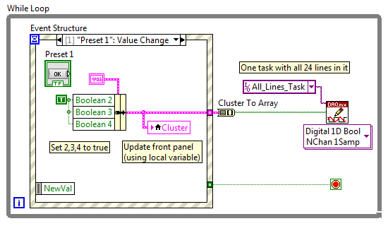
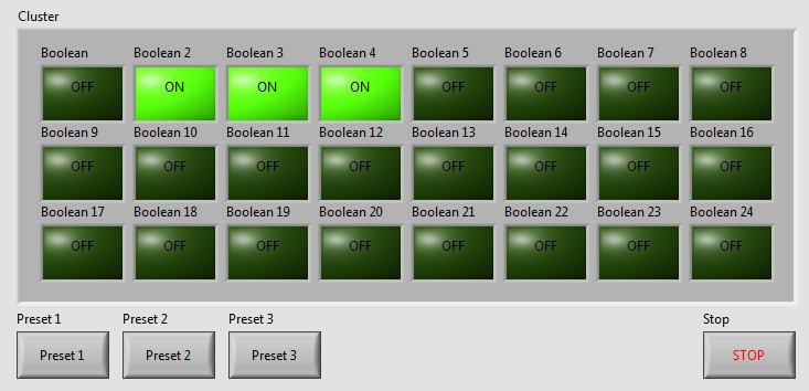
I've written a VI with 24 buttons, one for each output of the USB-6501, for turning on and off 24 relay. Now, I want to add more buttons that activate and deactivate the outputs multiple. We will call these Presets buttons and pressing the Preset button a few outings turn and some turn off. Get it? The VI I've included a screen shot is used to test a transmission controller and rather than to manually select one at a time relay I want a preset button that sets up instantly relays for the next stage of the event.
The VI I wrote uses tasks created in NI MAX.
I am a beginner of Labview, so please try to keep your easy to understand solutions if possible.
Thank you
Kevin
BTW, I'm registered in Core 1 and 2 month next to Richardson, Texas.
Here's an example - you will learn about the grapes, berries, events, etc., in the class, but this will give you a head start. Code is attached but I took a screenshot to give people an idea of how simple the schema becomes:
As your learn about them, I suggest you also make the cluster a TypeDef and make management mistakes, but I've omitted the example to keep things as simple as I could.
Good luck, LabVIEW learning, it is worth!
~ Simon
-
NEITHER USB-6501-24-line digital i/o (OR-DAQ) with LabWindows/CVI 7.0?
Hello
Can I use a recent NI USB-6501-24-line e/s digital (OR-DAQ) with LabWindows/CVI 7.0, although Labwindows/CVI 8.x is required?
Thank you
Dayne
Hello.
In DAQmx Readme, you can see which version of the CVI are supported by the version of current DAQmx. For a map of 6501, 8.7.2 or DAQmx 8.9.5 versions work.
Concerning
-
Pull-up external USB-6009. digital output (open collector) allows onboard external + 2.5 V output?
Pull-up external USB-6009. digital output (open collector) allows onboard external + 2.5 V output?
Hello
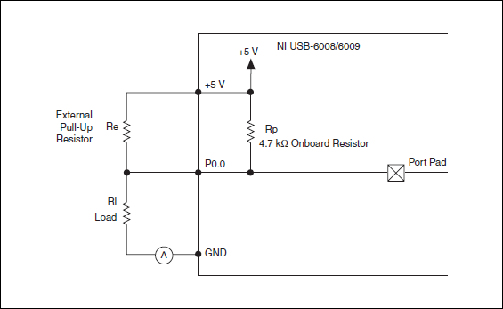
I want to config output digital USB-6009 to + 2.5 V above and 0 V digital output low. I know I can config USB-6009 digital output open collector with resistance to pull-up external, that can be applied with + 2.5 V power source.
My question is: can I use USB-6009 Board + 2.5 V output as the current source of resistance to pull-up? What resistance is a good number for the resistance to pull-up, if I can use this configuration?
Thank you much for the help.
Cathy
Hi Cathy,.
The digital USB 6008 front-end server looks like this:
So, there is actually an internal pullup to 5V 4.7 kOhm resistance when the device is configured to open collector.
If you want to display 0 to 2.5 V, I would look in a resistance of polarization of 4.7 kOhm between c and ground (according to the rest of your tour).
Best regards
-
Hi all
I have a brand new NI USB-6501, and I'm looking for more help with the operation. I'm running OS X 10.11.1, LabVIEW 2013 SP 1, NI-VISA 15.0 and NOR-DAQmx Base 15.0.0. I set up and plugged my module and get the flashing green light stable. I ran NI MAX, found the module and renamed 'Motor_Module '. Then, I went to my DAQmx Base of examples and found the Control.llb Interactive USB-6501 and ran the interactive VI control that is contained in this library.
The first thing I tried was simply running the VI. I got error-200220, device ID is not valid. I changed the name of the device to "Motor_Module" and run the VI. This time, I got error-200558, a task cannot contain multiple independent devices. Create a task for each independent device.
And here I am. My ultimate goal is to have this output module signal collector type open to + 5 V. Any help would be greatly appreciated. Thank you.
Hi Sullivnc,
I would recommend you look at a few examples in the Finder for example of OR. Under input and output hardware, there is a folder for DAQmx who has a record for a digital output which has some useful examples. If you do continuous or left over, you can add more stuff to your code as a clear task DAQmx, vi DAQmx Timing, and/or vi DAQmx task is made.
-
USB-6501 - impossible to find a basic example of Labview
Hello
I recently bought a USB-6501 card and I used it in my own succesfully end and C++ programs using the DAQmx drivers.
Then I tried to move to Labview 2009 (I never used Labview) so I looked for a simple example.
I tried to boot from the example 'interactive Control Panel' (http://digital.ni.com/public.nsf/allkb/AF0F31EE5D2AD23F862573140009D7C2?OpenDocument).
I had to install the 'DAQmx Base' for him to start, as described in the previous link. now it begins (before Labview attempted to get a few missing .vi) but I get a message "error 200220 occurred at an unidentified locatio.
Then I realized this example is 'old' (as explained here: http://forums.ni.com/ni/board/message?board.id=170&thread.id=209247), and it is suggested to look for a new one in example Finder ' entry-level equipment / output-> DAQmx-> Digital measurement (or generation)-> read Dig Port.VI.
I tried, but along the way ' entry-level equipment / output-> DAQmx-> "only a folder named"Analog Measurement\Voltage"exists.
Also in the search for 'Reading dig Port.VI' does not work.
I've already spent many hours in this research and tent and the fact that I am not able to find not even a basic example, it is quite frustrating and it is making me give up the idea of using Labview.
Please can anyone give me any suggestions where find/download an example simple and minimum to use my USB6501 in Labview 2009?
Thank you
Scipione.
First, install DAQmx Base was a mistake. Uninstall it and then install the Driver-OR-DAQmx. The driver must be installed after the installation of LabVIEW. After installation, make sure that the device is listed in MAX under "DAQmx devices. If it is not, your installation is still not correct.
To search for example LabVIEW, see help > find examples. Under Input and Output hardware > DAQmx, you will find the digital generation and numerical measures. You have to look at the simple, timed software examples such as read write dig Chan, writing Port to dig, dig chan, reading Dig Port. You also have the option to use the DAQ Assistant.
-
Hello world
I use an NI USB-6501 and I'm trying to understand how to read the entries.
I used this card to generate output using the example vi write Chan digging, it works fine.
Now, I'm trying to use the example of reading dig Chan vi to read an input voltage. But it seems that, by default, the map reads 5V (a 1 logic) as entered on each pins, even if nothing is connected to them. I tried to connect the output to the input, use a relay to see if it detects a change in the entry, if we send a voltage or not, but it changed nothing. It still reads 5V anything.
Can someone help me understand how to be able to read an entry? This problem has happened to someone else?
Thanks in advance.
Frédéric
If you dig through the data sheet, you will see that there is a 4.7kOhm shoot all digital inputs. So with the floating inputs you will get a high (logic 1).
As Dennis have already said, wire your digital output directly into your digital input. So everything that you set the output that you will read on the entry. I don't know what you do with a relay.
-
USB-6501 and opto-coupler SFH615A
Hello
I'm driving an opto-coupler (Siemens SFH615A - spec link attached) using the USB-6501. I am really a beginner and I am looking
help on how I can connect it. I have tried a few options already but no luck.
http://docs-Europe.Electrocomponents.com/WebDocs/009C/0900766b8009c194.PDF
I use a Servo-Drive in a project, a motor drive. Unfortuantely USB-6501 turns out logically lines high on the servo-controller startup is
receipt of a signal. I hope I can pass the INHIBITION of the servo drive line, through the opto-Coupler, so when you start 6501 will cause the optocoupler
circuit close to inauguration of the line inhibit preventing displacement engine. The labview program will make the logic of the bass line to allow the engine to move.
Looking at the manual of the USB-6501 and previous questions, there are 2 ways to do this, but working on resistance, values etc. required is
still a bit beyond me, and unfortunately I'm a bit stuck for the moment.
Any help would be greatly appreciated, thank you.
OK got it works, I hope it will be useful for others.
My problem, I think, have no idea really, is the impedance of the I/O device. Despite everything, I used a buffer of gain of the unit with the help of the
Intersil ICL7611 powered by the + 5V line with the line of digital output connected the + IN the axis of the ICL7611. On the output, I have a
Resistance 120 ohm before the opto SFH615A. Opto is open beginning 6501 and high but closed low logic logic. Happy days until the
the next problem happens

-
Best way to generate the software clock for USB-6501 of Measurement Studio for c# VS2008
Hi all
I wonder if there is a better way to generate a clock software for USB-6501 of Measurement Studio for VS2008 in C Sharp?
I have developed a clock using C Sharp "Thread.Sleep (msecPauseTime)"; and statements to switch digital output high and low. There are a few things I noticed in creating a software clock in this way:
- The smallest delay by the Thread.Sleep command time is 1 millisecond (which means higher clock period is 2 msec-500 Hz, not holding not ball account no. 2 below).
- Sometimes the delay I see on an oscilloscope is considerably longer than the delay that I specified in the sleep command.
In my application, I create signals (a clock, a latch enable and data series) to control what an attenuator step through the USB-6501 RF connected to a USB 2.0 on my computer. This particular step RF attenuator can accept clocks with frequencies up to 10 MHz, so I would like to generate a software clock (without having to connect to an external clock to a line of input on the USB-6501) which is closest to this maximum frequency, and I think that the USB2.0 line could handle clock speeds over 500 Hz. Also, I would like to know why the delays that I see on the scope are sometimes longer than the time specified by the Thread.Sleep command. Is it caused by the suspension of the execution of my program processor for something else, as I suspect? Of course, this isn't a big deal, because it does not affect the time as my serial data and pieces change compared to my clock. However, I would like to know why it does this.
I appreciate your help.
Thank you
Jonathan Becker
Doctoral research engineer
Carnegie Mellon Silicon Valley
Jonathan,
Since the USB-6501 DIO is software programmed, you are at the mercy of the planning of the operating system and won't be able to work reliably with an external clock in the software.
You can try to set the priority of your thread 'generation of clock' to improve performance, however, because Windows is not a deterministic operating system, there are still no guarantees. Operating systems are not required to honor the priority of threads. You can find examples and information on the definition of the priorities of the threads in c# here:
http://msdn.Microsoft.com/en-us/library/system.Threading.thread.priority.aspx
Kind regards
-
Too low current performance with USB-6501
For my measure I connected to an output port (output high voltage, 28 pins) with resistor of 10kOhm to ground (Pin 32). For the active reader to type out in car, I measured a 3.33V voltage and current of 0.33mA. I repeated the same measure with open-drain configuration, which leads to 3.27V and 0.33mA. I use NI-DAQmx and changed the disc type of output with a property node in labview 8.5.1. High-voltage output was generated with labview. In a second step, I put out high voltage with the able Control Panel & automation of DAQmx which led to the same result.
For my measure I'd wait a current higher return especially for active training mode, since the specification indicates a voltage between 2.8 and 3.6V for 2mA. I don't understand why the output current is not 0.5mA which would lead to 5V.
If I do the same measure with the + 5V output (PIN 31) source instead of the output port (pin 28), the current is as expected 0.5mA and 4.8V power can be measured.
For all measurements, I used a NI USB-6501 which has already been tested by an engineer from the Canadian standard.
Hello James Mc.
Thanks much for the reply. To reach the CMOS specifications (between 3.5 and 5 v) I add an external pull-up resistance and use to open-drain output ports.
Kind regards
Priska Studer
-
How to generate a continuous ttl signal with a USB-6501
Hello everyone,
I am a beginner with LabView, so maybe my problem, it's very easy to fix.
I need to generate a digital output using a USB-6501. This TTL signal will then switch to a device. Basically, I need the digital output to be permanently to TTL high level until a user active departure is given. Then the digital output must stay to the TTL low level until another stop active user is given.
Does anyone have any suggestions on how to do? I have failed so far to get something different high TTL to my USB 6501.
Thank you very much.
Hi there, take a look at the VI I enclose. You can find more information about the device in textbooks and on this forum. I hope this helps
-
Trouble with USB-6501 with Labview 8.6 Pro for Mac OS
Hello
I have a unit USB-6501 I try to use with Labview 8.6 for Mac Pro to processor intel.
I have the driver NOR-DAQmx base 3.2 for Mac installed and when I ran "Isdaq", it detects the device and also warned that the firmware needs to be updated. So, I ran the "FWUpdate" for updating the firmware. I double check the Isdaq and it detects the device as "NI USB-6501:"Dev1"(USB0::0x3923:0x718A:014386 B 0: RAW).
Now, when I run Labview 8.6 and DAQmx Base create channel VI and the port of 'physical' wire to the control, nothing appears in the available device.
Also, when I run the mxbaseconfig program, not the existing basic tasks detect the device.
Could someone please help me get this to work? Basically, I need to read and write slow digital data through USB-6501. But, the Labview does not detect the device.
Thank you
Keong,
I do not know what causes this, but place a task create VI before your code and the wire of the output task to the task of entering the chain and try to run that. Please let me know if it works for you.
Maybe you are looking for
-
How can I get the menu with 3 small bars icon in the upper right?
The menu represented by a 3-line icon, usually located in the right corner of the window, disappeared and I need the return! It gave access to a bunch of things like bookmarks, tools, extensions, and other useful shortcuts. I'm not at all technique a
-
Extension of love at first sight. Will it work?
The thunderbolt attached my Thunderbolt display cable is about a foot short of my Mac Pro. I see where it is is an extension of 1 meter (man/woman), available per person interposed. This will affect working on FCP X on my screen? Thank you. See you s
-
I'm curious y at - it free software that you can drag and drop all your kind of music it the way you want then she have automatically set the track 01 to 4,000? I found one that allows me to remove the whole ID3 tags but just can't find one that allo
-
I know this is a forum "Windows-related" but I am convinced that someone knows the answer. In Firefox, F11 is the option "full screen" and F12 opens the "Developer Tools Console" - sometimes I press F12 by mistake (instead of F11) and open the 'Conso
-
Road Rash is compatible with Windows 7 64 bit
Cannot install the buttocks of the road... It is said is not compatible for 64 bit... is there a solution to this without having to download another 64-bit version... ??