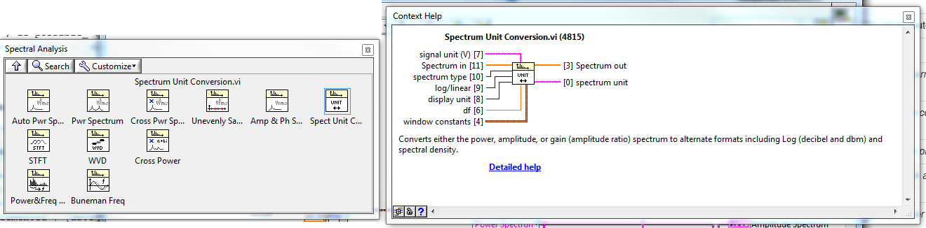
Unit of the y-axis of the power spectrum
Hello
I am acquisition of acceleration of an IEPE accelerometer. Units of the axis y of the signal in the time domain are in (g). The signal in the time domain is then injected into the Spectral VI Express measures to obtain the power spectrum of the signal. In the Spectral Measurements Express VI, I put the results of linear and the window (Hanning). My very basic question is: what will be the units of the axis y with the linear option power spectrum and how can convert their return to unit (g). If you provide an example of calculation that would be very appreicated. One of my simple code is attached.
Concerning
Unit Conversion VI spectrum lie in LabVIEW palettes: functions > Signal Processing > spectrum analysis
Tags: NI Software
Similar Questions
-
'power' and 'size' in the power spectrum?
When I choose "power at the stage of the power spectrum, numbers in my data were negative. I don't understand why. What is the difference between "power" and "ten factor"?
And what are the "dB" and "linear" in the average of actual size selection? "DB" means the following equation? Vnorm = 20 * log10 (Vnorm)? 'Linear' means greatness?
Thank you very much!
-
Hello
I have a question about BER and SNR and I would appreciate your help.
I have a power Spectrum (live with the presence of interference) and I would like to know in what parts of the spectrum, I can achieve a target BER (lets say 10th-3)
My suggestion was to first determine the signal investment ratio on the graph (for BPSK) and then search for available positions in the spectrum that can give me this SNR
So say for 10-3 BER, en No. DB 9 (on the graph)
If Eb (dB) = 9 (dB) + No. (dB) or Eb (dBm) = 39 (dBm) + No. (dBm)
now my questions are?
1 - instead of BER can I focus on NRS and are my calculations correct?
2-noise background in my power spectrum is observed from BDP-110-130 dBm is not a value constant .what should I do in this situation to find Eb?
3. What about interference? because WLAN is perhaps the received power - 50dBm in this situation that the SNR appropriate therefore to achieve this BER?
is it correct to say Eb should be = - 50 + 39 (dBm)
I thik find positions them avaiable in the spectrum (especially 2.4 GHz) to achieve a certain BER or SNR should not be as easy as I think.
Hi tintin99, the calculation seems to me.
For the second question, I don't know what application you are considering, so it is difficult to answer. If you measure performance to highlight, I'd go for the peak noise. To help us to give an exact answer, you provide more information about your application. For example, NEITHER-6115. The following link will be useful: NOR-6115 noise floor.
In case you're only interested in theoretically calculate the background noise, please check for the radio receiver noise floor. According to the definition, you can calculate the background noise as follows:
Background noise =-174 + NF + 10 log bandwidth
Where NF is the noise figure.
I hope my answers help. Still once, for questions related to the concepts of communications, please try discussion forum, I mentioned above. RF meter of NOR, please post to measure RF devices
-
Coercian dot on the power spectrum
Hi all
Was just curious to know why I have a point constraint on my FFT power spectrum when it fed a waveform? I thought (and detailed help is agree with me) that a waveform has been the type of entry required. There may be more going on here that I realize, but clearly I'm not.
As a sidenote, I'll you this because I replace an express VI in an application, that they gave me to end up and the express power VI spectrum seems to give results that are disabled by the square of the input function. OK then that sentence makes little sense, what I mean is when I plug a function up to my DAQ board generator and supply a sine to a known frequency spectrum of power express VI sets out 16 Hz instead of 4 Hz, 2500 instead of 50. The spectrum of normal power VI works fine. Do not Express VI anyway but just curious.
Thanks in advance!
Is the matrix Y DBL? SGL or EXT would produce a dowry of coercion.
Lynn
-
How to increase frequency resolution in the power spectrum?
All,
I work on the analysis of data GET vi, and manage mucho when it comes to display a simple power spectrum which gives a precise simulation of sine wave frequency I use now. Most of the brain waves are between 1 to 50 Hz, and so I try to get a resolution of at least 1 Hz frequency. However, no matter what I do (increase the sampling frequency, use different sub vi and blocks), the chart plot only in frequency of 10 Hz increments. I know this must be a simple problem, but I can not find good documentation on this and would appreciate any advice anyone could give on this problem. I'm racking my brain here!
Nick
You need to acquire a second data to get the 1 Hz resolution. The increase in sampling rate only increases the bandwidth that covers the FFT.
Frequency resolution = 1/sampling
Scale of frequency rate of sampling/2 =
For your application, you will need to have a sample of at least 100 Hz rate. At this rate, you must purchase 100 samples to get the 1 Hz resolution. At the 1 kHz sampling rate, you will need to acquire 1000 points for the 1 Hz resolution.
-
Collect data from specific frequency of the power spectrum
Hello
I want to know how to collect data from specific frequency of power spectrum file. I'm trying to separate data from specific frequency of the original file.
This will depend on much how your data is stored. You will need a way to read the file in LabVIEW and then a way to identify the data you want. I often record data in a .csv file, then I use "Reading worksheet" to get the data in a table. Then, you can simply use 'Index Array' to get the datapoints you need.
-
Get the value of the frequency of the power spectrum
I'm rather new to LabView and want to measure the frequency of the peak in a spectrum of power of a real signal. In addition, I want this value of frequency and amplitude to save to a file. Right now I am able to trace a spectrum of power using an express VI, which gives me the correct frequency value in the graph.
However, I'm not able to extract the value of the frequency with different screws, I found in LabView after browsing through the various discussions in this forum. Can someone tell me please in the right direction? I use a digitizer NI PXI-5124 to record the signal in a rack of NOR.
If it is the dominant frequency you are looking for you can use the vi extracted a single signal. You can also change this vi to include the details of the search if it isn't the dominant frequency, I have not included it in my example, but you can check it in the help file.
Ian
-
Output power of the frequency spectrum
Hello
I have a pretty simple question. I m using the power spectrum of FFT and PSD vi. and have trouble understand output frequencies. If I understand the first line is DC-value and delta frequency then describe the following frequencies. But when I put for example in 8 points say sampling frequency of 4 Hz = 2 seconds of data to analyze, I'll be back 4 lines of data (including 0). If the first is DC, then the 2nd should be 1 / 2 Hz 1 Hz = 3rd place and 4th place = 3 / 2 Hz, but what about the frequency of 2 Hz Nyquist, why Don t I get this one? or is there something I don't understand?
I also tried the example of Units.vi of FFT spectrum and can understand, but I still Don t get it.
Help, please!
Best
Jesper
FFT returns to power in frequency bins. The frequency of the bins is determined by the Fs (sampling frequency) divided by N (number of points), from DC (0Hz). For your case, the table returned would be:
Bin 0: 0-0.5 Hz
Bin 1: 0, 5 - 1 Hz
Tray 2: 1-1.5 Hz
Bin 3: 1.5 - 2 Hz
So effectively Bin 3 holds the power of 1.5 to 2 Hz (which contains your Nyquist frequency).
-
Pavilion m9670ch Desktop: replacement of the power supply
I replaced the original power supply with another more powerful (550W) earlier, I bought a new graphics card. This power is very strong, that's why I bought a new DARK PRO 10 power SUPPLY ATX 550W. Now, the computer does not start. When I press the power button, the fan starts momentarily and stops again. All cables are correctly installed. I reinstalled the old power supply (fort) again and everything works normally (except for the noisy fan). I contacted the manufacturer of the unit from the POWER of DARKNESS, but he referred me to HP, because they did not have a solution, but it may be a peculiarity of the motherboard. What can I do?
Hello
Return the Dark Power Pro and get a Corsair CX500, or CX600.
-
the power of the spectrum graph and butterworth filter
Hello
I am beginner in labview, I want to see the power spectrum of the sound samples, I want to see if there is any reason in these samples.
I use spectral measure, and then I filtered with butterworth filter samples. For output I using waveform graphs.
Before filtering the signal, I'm in the x axis of the graph between 0-22500 and the data mostly in 0-2500.
I've tried to filter using these values (fs = 1000 Hz, 0.125 hz = fl and fh = 500 hz) and the graphics almost the same thing but the axis of the graph is between 0-0, 5.
issues related to the:
What is the x axis properties? Why is different, but the graphics are the same?
Make the mistake with the program?
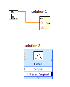
Hi Limavolt,
You have a problem with the bandpass filter VI, this VI generates only the signal of value i.e. table DBL. The signal is a cluster.
solution 1: you need to calculate 'dt' using the sampling frequency and use VI waveform construction to generate a signal's own scaling.
Normally, dt = sampling frequency/No. samples
Solution 2: replace the VI butterworth filter with filter VI express, this will produce signal without scaling.
-
bandwidth of the function "power spectrum".
I use signalexpress 2009. To analyze the acquired time signal from the area of the previous step in the same project, I applied the power spectrum function.
DAQmx Aquire step is configured as follows:
Acquisition mode: continuous samples
samples read: 1024
Rate (Hz): 1024
With this configuration, I expect a bandwidth of 0-512 Hz power spectrum analysis. Instead, the function of the power spectrum gave me 0-820 Hz frequency components.
How can I trust the result of 512Hz on?
I've attached screenshots of:
(1) my application project configuration
(2) result of frequency domain
Very useful information, thanks to you both for helping!

-
A Mac mini, purchased in the UNITED Arab Emirates can be used in the USA with only change the power cord?
Yes.
http://www.Apple.com/Mac-mini/specs/
the voltage may vary from 100-240 V AC.
-
Hi all, I bought apple phone I 5s recently is the power button / stop does not. Bought in the United States, but I was shifted to the India, the works of will to guarantee in India please help
Ask an authorized service provider regarding iPhones, a guarantee of a country may or may not be honored in another function where you take the device.
(143868)
-
Physical unit of the modification of the axis is in the path of a waveform graph
I would like to change the physical unit of a y axis in the plot of a graph (graph xy) waveform in the same way that I change the unit in a digital command. How can I do this? I use LV2012.01f4 32-bit.
Hi Joern,
Then, you apply a basic unit of your data before displaying in the chart:
The graph accept the numbers with unit (unlike my old message), but you must apply the unit to your data before you wire the table...
-
My iPad will not extinguish little matter how long I press the power button.
Why my Ipad2 refuses to turn off no matter how long press me on and press and hold the power button?
How can I get my rotation of the screen to work again? It has just stopped working even when switching screen lock is not selected in the settings.
Help, please.
Try a forced reboot. No data is lost during this procedure. Hold on the sleep and home buttons at the same time for about 10 seconds until the Apple logo appears on the screen. Then, rotate the unit and try to stop.
Maybe you are looking for
-
How can I delete data on internal HARD disk, and then reinstall OS X
-
I can't get bank statements to open on my desk, but they work fine on my laptop.
I can't get bank statements to open on my desk, but they work fine on my laptop. What has changed? Original title: pdf statements
-
How to enable the AHCI for SSD on M6-1010TX laptop computer HP
HELO Have tried to install an EVO of 840 Samsung 240 GB SSD on my laptop of M6-1010TX with WIN7x64 i5/4 GB and running. The SSD seems to work OK, but I when I run Samsung magician this is a warning that it must be set to AHCI. Also, most of the menu
-
How to put pictures of file to the folder in windows 7
Images, I want to move image files in a folder. How do I in a way much less time creating a folder, then drag each picture in it? 400 photos take forever! I'm a novice at this business of the computer.
-
Strange behavior of the browser blocks SQLDEV DM
HelloI feel some strange behaviors in the browser of Datamodeler.After the opening of my modelI have doubleclick in the window of the browser to fetch a few properties of the index:Drawings and models > MyModel > relational models > my RelModel > mod