USB 6008 data acquisition: automatically turning in a port
Hi all someone could please help me.
I need to autoamtically send output didgital since my data acquisition based on a value. the bottom of my little project. I read in a database if a value is equal to a certain value, I want to send a digital camera of the signal of acquiring data in a relay, so for example if the value 1 database generates a digital signl 0 7 port line.
If someone could help it would be much appreciated
So what's the problem with sending AUTOMATICALLY one. You simply compare the value of the database. A comparison function returns a true or false, which is quite ideal to display a true/false signal.
Fix the code you wrote. This is not a service of howework and see some code real goes a long way to get detailed help.
Tags: NI Software
Similar Questions
-
NEITHER USB 6008 AI acquisition and generation of pulse
Dear users of LabVIEW,
Greetings for everyone. I am a beginner of LabVIEW and I have a problem that I solved partially. I would really appreciate your help and suggestions that I searched for days without a bit of luck. The problem is as follows:
I am the acquisition of tension HAVE (continue) 4 to 8 accelerometers. In the meantime, I send you a digital output signal each time when you click on the sampling frequency (i.e. 1000, 2000, 3000,...) If the sampling rate is 1000). In other words, try to send a signal of output digital (at a frequency n Hz) at intervals of 1 second (depending on the material). To make the digital output signal begins to blink a LED every one second. In addition, I need to write signals (voltage) AI and the LED blink timestamps PC (software) separately. All stages of the above are followed in my .vi program, but the real hardware/software level operations kill my timestamps. In other words each LED flash timestamps are not accurate, when I use LabVIEW measurement file express VI (the difference is not at least to the third decimal). In addition, the timestamp is kinda OK when I disable the file LVM write VI. Onemore thing I've noticed is that physically the LED blinks every second two times, I feel it's because of the shift register and loop delay of a second. Is there a way to control the speed of blinking (i.e. Boolean State must change to every 500ms without delaying the inside while loop).
Results and comments:
LabVIEW 2011 .vi, timestamp of files with or without generator of LVM (express VI) files are all attached. Please note that there is a considerable amount of drift in the consecutive timestamps when the file LVM generator is used, on the other hand there are derivative of 0.001 ms when the file LVM generator does not. The reason for horodateurs PC have is about aligning the various measures or observations or events to global time scale.
Please give me any suggestions or help me do at least accurate to milliseconds in VI of witten. Finally, is there any USB DAQ module relatively inexpensive which allows to send an impulse to directly from channel impulse of output digital channels when the "n" sampling frequency Hz is obtained by level of material which could all be accurate, so that the software timer is completely reduced to a minimum. Although there are very material sophistiated of NOR, but our goal of this project is to build and test the system profitable.
Thank you and I really appreciate your time and effort inavluable. Have a great weekend!
Just change the samples to the constant playback at the entrance of the DAQmx Read.vi from 1000 to 500.
Lynn
-
Chip exchanged on the issue of USB-6008
I have a USB-6008 data acquisition that went wrong in a set-up. The MCU was getting very hot while it is plugged (I had a ground problem that it fried). I ordered a new microcontroller and succeeded him, now he does not become hot at all when it is plugged in but I need for the flash I think. The argument of doing nothing, the indicator light is not flashing and the computer does not even recognize whether he has a connected device if he acknowledges.
Has anyone here done a repair like this?
Where can I get the software to Flash the chip and can be done on my site?
Thank you all,
Hi ChillyWilly,
You should contact the Customer Service and seek to return the unit. If it is within 30 days of the purchase, this should not be a problem and would be much easier to try to flash the device yourself. You will need the serial number of the device when you call. Hope this helps!
-
With the NI USB-6008 case error-200077
I try to run the C program example with my NI USB-6008 data acquisition card. I am trying to run the example of "ContGen - ExtClk.c". I get the following error when I build the program:
DAQmx error: the requested value is not supported for this property value. The value of the property may be invalid because it is in conflict with another property.
Property: DAQmx_SampTimingType
Asked the value: DAQmx_Val_SampClk
You can select: DAQmx_Val_OnDemand
Task name: _unnamedTask<0>
State code:-200077
End of the program, press the Enter key to exit
Thanks for any help.
Have you done a search for this error code? As you can see on the care for the 6008, the analog output is only software timed, so you can select calendar on request. Your real update rate will vary a little, and according to specifications, have a maximum of 150 s/s.
-
New to Labview, need help. USB-6008
Hi there, let start by saying, I'm totally new to Labview. I have experience of programming in C, C++, VB etc, but never in Labview. I thought that Labview is not much of a difference, but I was very wrong. I went and bought the acquisition of data USB-6008 and downloaded the trial labview to explore and I am totally stuck and have no idea how to proceed. I can start over again and probably learn all the basics, but I don't want to take too much of my time. in any case, here is a description of my project:
Configuration: USB-6008 - to measure the voltage of a battery lithium ~3.6V
Circuit printed with a switch either connects the battery resistance or not. the switch can be turned on and off by a USB-6008 analog voltage output
What I want to do in pseudo-code:
If you click START,
Take a read of DAQ and shop to chart and indicator of voltage 1
If the voltage is > 3.6, then
30 seconds
a voltage data acquisition to turn on the switch and light load lights output
read DAQ and update graphic and indicator of voltage 2 reading
If it is DAQ< 3.5,="" status="" indicator="OFF," else="">
30 seconds of the end loop
If the last reading after 30 seconds of DAQ is > 3.5, the message 'pass' else a message "fail".
on the other
indicate a voltage lower than 3.6V and stop the program
end if and stop the program.
NOTE: the voltage indicator 1 show ONLY the first reading before the circuit switch is on.
I didn't know that it is very difficult to program, because everything is very basic, but since I don't know Labview, I do not know how to proceed. a front is attached.
Thank you for your help.
John
Hello!
To start, here are a few things.
1. learning LabVIEW:
This has all kinds of videos step by step based on LabVIEW and is a great resource just start... it's really great because you can click on a video about any topic that interests you. There are a set of tabs at the top that categorize videos.
2 examples of DAQ. In LabVIEW go to the Help menu > examples of find... Then in the window that opens (this is called the Finder of the example) you can navigate to the material file Input and Output > DAQmx > Analog measures > voltage
We have tons of DAQ examples, so this should at least allow you to read a voltage quickly.
I hope this helps!
-
the relay control data acquisition
I am creating a vi that controls (press and release) several relay using a USB 6501 data acquisition. This should be a task relativily easy but I get flumoxed by errors. I tried to use the examples, but I get an error telling me that I need to use the mode of generation 1 sample (on request). Help, please
Sure. The easiest way is to have a DAQmx writing followed by a function of delay, followed by another entry, followed by another period. Simply plug the error links in order to control the flow of data. However, the VI would be insensitive so you can use a state machine or function elapsed time so that the VI can be stopped without waiting for waiting for him at the end.
-
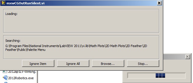
Acquisition of data NOR usb 6008: a strange problem: mxwcgoutrunsilent.VI is not respected
Expensive OR
Today, I bought an acquisition of data NOR usb 6008
and I'm using labview in 2011
the problem is appear when after I end the process of configuration of the i/o data acquisition Wizardthe following image shows the mxwcgoutrunsilent.VI is ignored and an error has occurred
someone can help provide this VI for me
What is the complete labview modules can also so I could do a real time data acquisition
Best regards
mangood,
You received an error code? If so, what is it? What version of NOR-DAQmx driver you have installed? It seems your driver potentially incorrectly installed, and you may need to reinstall the driver.
Here is the link to the latest version of the NOR-DAQmx driver: http://www.ni.com/download/ni-daqmx-9.8/4297/en/
-
Looking for a way to mount an acquisition of data USB-6008
Anyone has a suggestion for an acquisition of data USB-6008 mounted on a Panel. I use it for a system where it should not be loose. I have a few ideas, but hope that someone smarter already has a good solution.
Thank you
It is not a robust application, but the box will be moved and I don't want it put in the open air. I simply put a velcro pad on the back and the atttaching in this way. Should be all I need.
-
Data acquisition with USB-6008 using C++
Hello
I am trying to use USB-6008 to collect analog data without using Labview, since I can't afford the lincence. I searched in the C++ provided with product samples and found "Simple example of analog input.
The compiler I use is codeblocks instead of visual studio (once again for monetary reasons). The code seems to works since when I run it with the USB-6008 box connected, he wrote "gains 1000 points.
I have 3 questions relating to the use of this code:
1. where are stored the 1000 points?
2. How can I modify the code to specify the time acquisition and the frequency of acquisition?
3. How can I change this code sample points simultenously with 8 analog inputs?
Thank you for your help,
I'll try to add any clarification if necessary.
Albany
Your questions are answered in help for c programmers.
1000 points are in the variable array of points called 'data '.
The sampling frequency is set to sync.
The number of points read is defined with the function of reading.
Read channels are defined with the function channel set. To read multiple channels, use syntax such as Dev 1 / ai0:3 for the first 4 channels.
-
6361 versatile usb data acquisition does not automatically detect the SCXI chassis/accessories
versatile usb data acquisition 6361 will detect automatically SCXI chassis and accessories?
Hello kdCMC,
As far as I know that the SCXI-1600 USB Module is able to auto-detect SCXI Modules.
This is also mentioned on page 11 and 12 of the following SCXI to start document:
http://www.NI.com/PDF/manuals/373236m.PDFAll data (including USB-variants such as the NI USB-6361) have only a 68 pin shielded cable (IO) between the DAQ hardware and the SCXI chassis.
This cable does not auto-detect opportunities since it basically just "transfers analog and digital signals" between SCXI chassis and DAQ hardware.Is there a specific document that created the confusion on this subject?
-
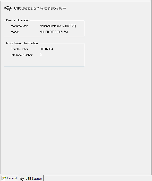
Acquisition of data USB-6008 not detected in LabVIEW
Hello
So my USB-6008 DAQ hardware is not available when I do a new task DAQmx (or open the DAQ assistant).
I found this link: http://digital.ni.com/public.nsf/allkb/179BC9B0266168288625722100738C22
I did everything just said but LV still does not detect my USB-6008.As you can see on the image below it is detected by the solution of measurement and Automation Explorer. I don't know how to test with visa test Panel.
After that, I tried to test with the diagnostic utility, and here it does not appear in the list.
I downloaded the appropriate (several times) drivers but still nothing.
Can someone help me with this?
-
How can I improve the rate of acquisition with daqmx and usb-6008?
Hello
I am trying to acquire data of analog voltage with a USB-6008. I'm under Labview 8.5 student on an HP laptop with a 1.33 Ghz cpu and 736MB RAM, apparently. I tried using the Daq assistant and the low-level Daqmx functions. My best results come with a task set in MAX for my analog input, and using the function 'Daqmx read' the 'unique double 1 d sample' value in a while loop. I insert the values returned in a table which built in the while loop, and then when I'm done, I check the number of samples in the table. In the test VI attached, I also use the time to Get before and after all loop. The best sampling rate I made using this method, is around 40samples/second. I have attached a VI below that illustrates this concept. In my actual application, the data acquisition code runs at a time while loop with 1ms, parallel to other code that controls the device I'm collecting data of. The sampling rate is roughly the same for my test below VI and my application program.
The 6008 datasheet gives the sampling frequency maximum 10 kHz. I'd be happy with 2 to 2.5 kHz, or as soon as possible; I'm sure that I can achieve a little more than 40 Hz. My first idea was tied to the hardware, but the 6008 cannot make acquisitions NI hardware.
My question is: How can I implement a faster sampling of analog voltages to a USB-6008 in LAbview? If I can't do it, is there another way I can taste the data more quickly?
Thank you
-SK-

To the best of my knowledge, the USB-6008 can do timed equipment acquisition. Don't forget that this is a multiplexed device, so if you add 8 channels so the maximum you can set is 10 k/8
If you are new to LabVIEW, I suggest that you try this sample program first
\examples\DAQmx\Analog In\Measure voltage. llb\Acq & Graph tension-Int Clk.vi Amit
-
Exchanging USB data acquisition systems
Hello
I'm looking to use the same program in labelled while sharing the acquisition system of USB-6210 data with the same program. I use labeled 8.5.1 and have a voltage reading program. What I find, however, is that the .vi program does not seem to acquire on the software side, when I disconnect the USB-6210 I use and plug in another, but the same hardware system model. The Green LED on the material will begin to Flash, but there is no entry in the charts of the program. To measure the voltage, I use the function block "DAQ Assistant" to connect to the analog channels in this system. To work around this problem, change the DAQ Assistant function for the device interchanging at work (delete and use the wizard to generate a new DAQ Assistant). It's quite heavy but doable, however, the hope is to apply this program and equipment to several sites, each with their own system of fittings. Is there a way to exchange the hardware systems, but keep the same program so that it might be a way around this? I also used the Application builder to generate a stand-alone program for it but the same problem occurs. Is there any recommendations for multiple devices, or am I missing something? Thank you very much.
Whenever you connect a new device, it gets its own device ID.
from Dev1, Dev2 etc..
So either rename in solution of measurement and of Automattion (MAX) Explorer or use another parameter in the daq assistant.
-
data acquisition stops automatically
I want to stop assistant DAQ automatically after a period of time, so I created this VI.
When I start the program, it work and after reaching the value of time specific 50, the graphical indicator ' looks like "stop, but wait after 9999 second, the graphical indicator suddenly see a lot of data that seems to be taken for the 9999 seconds, what is happening? After that, it gives an error saying:
Possible reasons:
Attempted to read samples that are no longer available. The requested sample was already available, but has since been replaced.
Increase in the size of buffer, most frequently the reading of data or by specifying a fixed number of samples to read instead of reading all available samples would correct the problem.
Property: RelativeTo
Corresponding value: current playback Position
Property: Offset
Corresponding value: 0Task name: _unnamedTask<100>
Data acquisition cannot be stopped like that?

Thank you
Not quite. Like this.

-
We send 5v data acquisition using a voltage generator. Hook us it up to a voltmeter and see 5V. When connect us the generator voltage to a valve "normally open" parker, the voltmeter indicates .14V. It seems that when we connect the two sons of the valve for the voltage generator, the son act as pattern. We want to control the voltage flowing to tap through Labview. We checked the wires to the valve and they work very well, because if we send a constant 5V since the acquisition of data and put ashore, she, the voltmeter indicates 5V. Someone knows why the son act as pattern and low blood to .14V?
nsatpute wrote:
Our data acquisition is NI USB-6259. The valve requires only a 5V max and our DAQ provides up to 5V. However, after connecting the valve to the acquisition of data, the grave tension to almost 0. We start from the principle that the son somehow act as the reason, but we are not sure if this is the case.
The question here is not how much voltage the valve wants, it's the current needs of the valve. The 6259 can put only 5mA via an analog output. Your very likely tap needs much more than that. If you need to add in an amplifier circuit that can supply more current to operate your faucet.
Maybe you are looking for
-
How to wake up the iphone 6 sec without pressing any button
How to wake up the iphone 6 sec without pressing any button, which will help you maintain your buttons on the iPhone. Please let me know if you have any ideas on this subject. Thanks in advance.
-
I now have my I have restored air that went from my PC
My I Tunes said that I had to reinstall I think I did. I am 82 and it's all very confusing to me so please be patient.
-
Portable printer HP 150 ~ Bluetooth
I have a mac book air and I try to connect to the Hp 150 mobile printer via bluetooth, but when I click on pair it says pairing failed. I then click on options and it asks me for a code and I don't know where to find the code... Someone please help!
-
Original title: "RESTART YOUR COMPUTER IS REQUIRED" MESSAGE LOOP Whenever I start my computer with Windows XP, I get the message "it is necessary to restart your computer. If I select 'YES', the system restarts and I get the same message. Always sh
-
Cannot enlarge the thumbnail view in my analysis of file
The thumbnail views are 10 across the page. You will have to show all my scans of large miniature views.