USB 6008 digital output signal
I am VERY new to LabView and have been racking my brain trying to get digital output of my USB-6008. All I want is to be able to get a signal of + 5 V of my digital output when I click on a button. This signal opens a valve on a system I see so when it is pressed, it must stay open until I press the new button. It seems simple enough to me, but I'm not too familiar with LabView. Help, please!
Stripling07
You must first take the LabVIEW tutorials and then look at the links to get started with DAQmx .
The simplest program would be with the DAQ Assistant. Drop it on your schema, and then select digital output > digital line. Select the line when the wizard has completed, click OK. Wire a Boolean value in a table to build and the output of which is connected to the data entry. That's all. You can test the output of MAX (Measurement & Automation Explorer) with the test Panel. Do NOT test with your connected tap. Your valve may require more current that can provide the 6008.

Tags: NI Hardware
Similar Questions
-
USB-6289 digital output signals setting
I use a USB-6289. I am writing a CVI application that uses this device. I need to put the digital i/o pins as outputs. In the CVI app, I know I can create these tasks with the tools-> create/edit DAQmx tasks. He created this:
Int32 CreateDAQTaskInProject(TaskHandle *taskOut1)
{
Int32 DAQmxError = DAQmxSuccess;
TaskHandle taskOut;DAQmxErrChk (DAQmxCreateTask ("DAQTaskInProject", & taskOut));
DAQmxErrChk (DAQmxCreateDOChan (taskOut, "USB-6289/port0", "))
"DigitalOut", DAQmx_Val_ChanForAllLines));
DAQmxErrChk (DAQmxSetChanAttribute (taskOut, "DigitalOut", DAQmx_DO_InvertLines, 0));* taskOut1 = taskOut;
Error:
Return DAQmxError;
}So this it puts in place but not to write the data. My question is what is the command to write the data?
Also I was wondering if the code source of any example that shows how these commands are made? Is it possible to configure the bits individually? I only need to use 5 of these pins as outputs so t would be coll if I could write that the bits D0 - D4.
Are there documents written on these commands and how they are used?
Thanks in advance
A DAQmxWrite writes the data.
Go to help > examples > material input and output > DAQmx > digital generation.
If you specify the lines instead of a port, you can use as the number of bits you want.
First glance using the ICB.
-
Pull-up external USB-6009. digital output (open collector) allows onboard external + 2.5 V output?
Pull-up external USB-6009. digital output (open collector) allows onboard external + 2.5 V output?
Hello
I want to config output digital USB-6009 to + 2.5 V above and 0 V digital output low. I know I can config USB-6009 digital output open collector with resistance to pull-up external, that can be applied with + 2.5 V power source.
My question is: can I use USB-6009 Board + 2.5 V output as the current source of resistance to pull-up? What resistance is a good number for the resistance to pull-up, if I can use this configuration?
Thank you much for the help.
Cathy
Hi Cathy,.
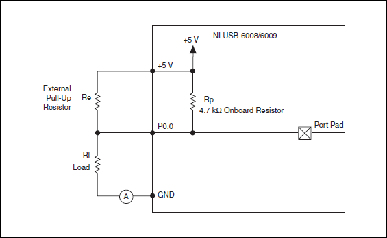
The digital USB 6008 front-end server looks like this:
So, there is actually an internal pullup to 5V 4.7 kOhm resistance when the device is configured to open collector.
If you want to display 0 to 2.5 V, I would look in a resistance of polarization of 4.7 kOhm between c and ground (according to the rest of your tour).
Best regards
-
NI USB-6009 digital outputs are active when connected to a PC - I'm not that
I have a small problem:
All outputs digital NI USB-6009 module become active when the module is connected to a PC when no VI is running.
As soon as I start my VI, which controls the module, all the outputs are disabled (now inactive).
How can I achieve this, outputs are inactive if the module is connected to a PC with no program running?
johanneshoer wrote:
I have a small problem:
All outputs digital NI USB-6009 module become active when the module is connected to a PC when no VI is running.
As soon as I start my VI, which controls the module, all the outputs are disabled (now inactive).
How can I achieve this, outputs are inactive if the module is connected to a PC with no program running?
The USB-6008/6009 case has a pull-up internal (4.7 kOhm) resistance. This causes the outputs digital on the device to have a startup logic high State. t is not recommended to use some sort of resistance of menu drop-down. However, what you can do is add octal buffer like the 74HC541 stamp and a digital output to control the sorting of the 74hc541 state mode. Connect the OAS and CEO input signal. A Summit on the pins of the latter will be sorting the output of the buffer State. Therefore, no output signal will be present until you pull the stems of low control. The USB-6008/6009 case have a 5 volt output (200mA max), you can use the buffer.
-
USB-6009 slow output signals using SignalExpress - error 200077
We have a Council of USB-6009 and Signal Express version 3.5.0
We want to generate low-frequency, analog and digital outputs to simulate some slow movement process.
We have created the signals and their generated as output, put when we RUN the project, we get error 200077, which seems to indicate that we must use On Demand distribution of signals.
If we choose On Demand, then the generate DAQmx says we have a missing entry.
So, what method should be used with the slow USB-6009 to generate box (.01Hz and slower) analog and digital outputs?
These are 2 of the projects, we tried - using On Demand, N samples, continuous, internal, and external triggering etc..
Thanks adavance for your help...
Welcome to the forums of Steve,
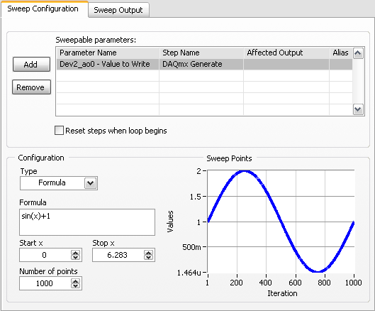
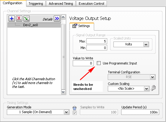
I have good news for you. I played a bit with the sweep and actually got a code facing up to generate a slow signal. I went and tested it with the 6009 and he was able to run without any errors. I joined here, but if you have to open (or anyone else in the future), here are some screenshots of how it works. If this works, feel free to make the forum as resolved while others can locate a solution a little easier in the future.
Scan Configuration:
DAQmx Config:
-
USB-6008 turning outputs ON and OFF
I'm new to LabVIEW. This is the first time I tried to write a VI that communicates with an external device. Everything I'm doing adjust tensions and put on or off the two analog outputs for a USB-6008. I don't read all the entries or do something with the outputs digital, I want to just turn out analog ON and OFF.
Here's what I have so far.
It does the job of setting that puts the analog output to the USB-6008.
The only thing left to do is to make an executable file. I don't have any idea on how to do it again.
I'm sure a true guru LabVIEWw could have done better, but it does the job.
-
How can I improve my 2 digital output signals calendar?
Hello
I use a NI DAQ Pad-6015 (usb) with Labview 8.5 and XP to generate 2 digital outputs (high for the first 500ms and 600ms high for the second). The moment didn't need to be very specific, so I use not the 2 outputs hardware clocks. When runing of VI, and measure the length of the outputs with an oscilloscope, I get s 520ms and 640ms. This isn't a problem, but I still want to know, if I'm doing the right thing in my program, or if it is possible to improve it?
Thanks for your help,
Kind regards
Marc
Hello
Using all your advice I have exact measure now: only 0 to 4ms delay for signals from ms 500 and 600 using the NI DAQPad-6015.
PS: Timmer was right regarding the notice of usb. With my previous program when you use a card PCI of 6229, I had only a difference of 10 ms instead of 20 ms with the usb one.
Thanks for your help,
Kind regards
Marc
-
NI USB-6501 digital output problem
Hello
I use DASYLab v.11 and I'm working on an interface with the NI USB-6501 where I'm putting a digital high on four ports.
With the module "NOR-DAQmx - digital input", I managed to read the digital inputs of the ' NI USB-6501 ".»
It's only the "NOR-DAQmx - digital output" I can't go to work.
Using 'NI MAX' of NOR I have easily can emmit my four LEDs in the way of my High/Low ports.
But not with DASYLab. When you use DASYLab tension on the ports remains unchanged.
Now, I have a switch module, generating 5/0, directly connected to the digital output module, which is assigned to my four output ports for my task.
I also tried with a module of relay between the two without success. I also tried to use 1.5 above instead of 5 without success.
I use the option 'Bus (0/5 supply) for the module "Digital output".
"NI Max", I configured the ports as "active drive.
Any suggestion of what I might be missing?
Thank you
Martin
Hmm, four ports, or four lines?
A port consists of eight lines. Each line can control an LED (ON / OFF ~ 0/5V).
If you have created a task to dig-out to control a port, 5V to this port sending sets all lines of this port to 'high '.
You need to 255 for each line one too high port (at the bit level: 128 + 64 + 32 + 16 + 8 + 4 + 2 + 1).<- eight="">
Or, you can create a dig out tasks to control four lines of a specific port.
Four lanes of the EEG DAQmx DigOut module.
Each of the channels of the modul will feed a single line of the task/device.
Four switches will then turn the lights, or turn off.
Make sure, that the 'bitposition' is the number of correct line (see picture).
-
I can read two-channel USB-6008 using THE Signal Express?
Hello world!!
Is possible to read the two analog inputs at the same time?
Example: Using Signal Express, I need to read the (channel 0) analog input and analog input (channel 1) at the same time.
I try this but, the signal on purpose gives me an error message saying that I can't read several channels at the same time using the USB-6008.
Is this true?
Thank you
Ivo João
André,
Grato definition of pela.
SUA ajuda muito util faith.
SDS,
Ivo João
-
USB-6211 - digital output not supported?
Hi all
I can't use the USB6211 device port... I use daqmx with Delphi7 API functions.
First of all, I tried this:
DAQmxCreateTask('', @TaskDO);
DAQmxCreateDOChan (TaskDO, PChar('Dev1/port0'), ", DAQmx_Val_ChanForAllLines);
DAQmxWriteDigitalU8 (TaskDO, 1, 1, 1, DAQmx_Val_GroupByChannel, $FF, @written, nil);I had an error in the DAQmxWriteDigitalU8:-200012 (= digital output not supported). (???)
OK, I tried to disable autostart option based on DAQmxWriteDigitalU8 and insert a 'manual' start in the code:
DAQmxCreateTask('', @TaskDO);
DAQmxCreateDOChan (TaskDO, PChar('Dev1/port0'), ", DAQmx_Val_ChanForAllLines);
DAQmxStartTask (TaskDO);
DAQmxWriteDigitalU8 (TaskDO, 1, 0, 1, DAQmx_Val_GroupByChannel, $FF, @written, nil);
DAQmxStopTask (TaskDO);Now, I got the same error in DAQmxStartTask:-200012 (Digital Output not supported, once again). (?????)
I don't understand.. 'Digital output not supported "? USB-6211 has 4 lines! What is the problem?
I want to just turn on and off the lines from code...
-Cs George-
Well, finally I figured out...

Here is the solution:
DAQmxCreateTask('', @TaskDO);
DAQmxCreateDOChan (TaskDO, PChar('Dev1/port1'), ", DAQmx_Val_ChanForAllLines);
DAQmxWriteDigitalU8 (TaskDO, 1, @dummy, 1, DAQmx_Val_GroupByChannel, @bitmask, @written, nil);Digital output lines are on port1! Corrected parameter.
And the part of the interface of DAQmxWriteDigitalU8 had to be changed (in nidaqmx.pas).
I don't know why, but the AutoStart (dummy) parameter in the DAQmxWriteDigitalU8 function is ignored: function always starts task automatically, regardless of the value of autostart. But this isn't a problem for me.-Cs George-
-
USB-6501 384 bit synchronized digital output signals
I need three digital signals (please see the attached file) to control a device, a signal is the clock signal, one is a continuous data signal 384 bit and another strobe signal that informs the device start and stop data. I have a USB-6501, this task can be achieved? I don't know how to write a 384-bit with DAQmx write signal, because it seems to support up to 32 bits. And it will be difficult to synchronize?
Thank you!
Hello the Stork
If you send 384 bits sequentially in a digital line; and running a timed software application, this would be possible (NI USB-6501 is a programmed software). See the example VI included below. In addition, please note that avoiding the nondeterministic East and will depend on the speed of your system. If you want to continue your application with one of our DIO cards that provide hardware timing capabilities; Please see the link below for more information about these devices.
Best regards
M Ali
Technical sales engineer
National Instruments
-
Error writing to usb-6343 digital output
Hello...
I have a trask to produce some digital waves... so I use usb daq-6343. to start, I am writing 1 simple value (i.e., 1) to the first pin of the port. but I get the error here, I enclose error png and part vi of the code... Please help me here...
Thanks & best regards,
-
NEITHER USB 6008 AI acquisition and generation of pulse
Dear users of LabVIEW,
Greetings for everyone. I am a beginner of LabVIEW and I have a problem that I solved partially. I would really appreciate your help and suggestions that I searched for days without a bit of luck. The problem is as follows:
I am the acquisition of tension HAVE (continue) 4 to 8 accelerometers. In the meantime, I send you a digital output signal each time when you click on the sampling frequency (i.e. 1000, 2000, 3000,...) If the sampling rate is 1000). In other words, try to send a signal of output digital (at a frequency n Hz) at intervals of 1 second (depending on the material). To make the digital output signal begins to blink a LED every one second. In addition, I need to write signals (voltage) AI and the LED blink timestamps PC (software) separately. All stages of the above are followed in my .vi program, but the real hardware/software level operations kill my timestamps. In other words each LED flash timestamps are not accurate, when I use LabVIEW measurement file express VI (the difference is not at least to the third decimal). In addition, the timestamp is kinda OK when I disable the file LVM write VI. Onemore thing I've noticed is that physically the LED blinks every second two times, I feel it's because of the shift register and loop delay of a second. Is there a way to control the speed of blinking (i.e. Boolean State must change to every 500ms without delaying the inside while loop).
Results and comments:
LabVIEW 2011 .vi, timestamp of files with or without generator of LVM (express VI) files are all attached. Please note that there is a considerable amount of drift in the consecutive timestamps when the file LVM generator is used, on the other hand there are derivative of 0.001 ms when the file LVM generator does not. The reason for horodateurs PC have is about aligning the various measures or observations or events to global time scale.
Please give me any suggestions or help me do at least accurate to milliseconds in VI of witten. Finally, is there any USB DAQ module relatively inexpensive which allows to send an impulse to directly from channel impulse of output digital channels when the "n" sampling frequency Hz is obtained by level of material which could all be accurate, so that the software timer is completely reduced to a minimum. Although there are very material sophistiated of NOR, but our goal of this project is to build and test the system profitable.
Thank you and I really appreciate your time and effort inavluable. Have a great weekend!
Just change the samples to the constant playback at the entrance of the DAQmx Read.vi from 1000 to 500.
Lynn
-
Hello
I have a USB-6008 read a signal to 5V on one of DIO ports. The 5V is or the circuit is open. Since the 6008 traction has internal open ups resembles a true TTL signal. I think using a 850 Ohm pull down on the output line. I think that should lose about 5.8ma when the 5V is present. 6008 for line specification is 8.5ma. The 5V is coming from a mechanical switch which is activated when the vacuum is applied, so that the switch does not consume all current... It seems to me that it should work. But............ Does anyone see a problem with that?
Thank you
Alan
Connect the switch to the Gnd and reverse the bool off the DAQmx Read?
-
Hello
I use a USB-6008 to read signals from analog voltage to a device I built. The task is configured with a single reading finished with a range of + -10 volts. There is no scaling in the task or in the block diagram, but when I acquire data in a PDM file and view it, I get a load of PieceWisePolynomial scaling properties. I have attached the TDMS spectator to this post.
Does anyone know where it comes from because I can't explain it.
Thank you
The data goes back as an unsigned integer between 0 and 32 k of the ADC on the 6008.
The scale is to convert this unsignedInt to floating point value between-10 and 10.
Maybe you are looking for
-
P70-A-11N satellite: cannot boot Linux from USB flash memory
Hello so far, I found no way to start an on-line system to a bootable USB key with a linux operating system installed.It is for sure a bios issue and the choice of preferences. Maybe someone has a solution for this problem! It's a P70 - A - 11N Noteb
-
iTunes does not update the podcast... why?
So my podcast, ' Onstage/Offstage', has been very well on iTunes for three years. All of a sudden it will not update new episodes, new graphics and text changes. I checked my file rss.xml several times and it seems very well as usual. URL: https://it
-
SPA962 commissioning custom background
Nobody knows what are the XML settings to provide a custom background of BMP on a SPA962? My firmware is 5.1.5. I can make it work from the web interface, but could not find the appropriate configuration settings. Thank you.
-
What are the BCD entries to TWO instances of dual boot of Vista professional in TWO separate hard drives? -Dell Vostro 1710, my wife had to be returned to Dell, I installed its Vostro hard drive in my Dell Vostro 1710 SAME, but I don't get a menu sta
-
The font size decreased. Almost too small to read.
the font size decreased if small it can hardly be read. This includes Web pages, and this page. I have shortcuts of co, but nothing else. How you change the size of the police when it affects all computer data?