USB-6008 LABVIEW 8.2. SINGLE CHANNEL WITH DBL INPUT VOLTAGE OUTPUT COMPARISON
I AM WRITING A PROGRAM THAT USES A SIMPLE USB-6008 ANALOG INPUT CHANNEL. I WANT TO READ CONTINUOUSLY THE VOLTAGE FOR 60 SECONDS. I WANT TO COMPARE A TENSION FOR THE PREVIOUS OF THIS SAME CHANNEL VOLTAGE, MAINLY FOR THE PERIOD OF TIME MAX VOLTAGE GIVEN, THEN GET A FINAL VOLTAGE READING. THE OUTPUT OF THE VI IS A DBL. I WANT ONLY TWO TENSIONS OF EXPORT TO EXCEL. TO SAVE TIME, I KNOW HOW TO EXPORT. CAN SOMEONE HELP ME WITH THIS ONE.
VI needs an register shift related to the Max & Min function. The current value would be the entrance is and the entrance of x is the left shift register. The max value gets wired for the shift register to the right. Don't forget to initialize it. The output of the shift register is the max you would write and the value of the DAQmx Read out of the loop of wire will give you the last reading.
Your waiting for 45 seconds makes no sense since you said that you wanted to read continuously. You also said that you wanted to read 60 seconds and all this logic is missing. A simple function of time elapsed, it's all you need.
Tags: NI Software
Similar Questions
-
Hello
I can't find any solution so that my usb usb-6008 interface works on LabVIEW 2011, DAQmx Wizard is missing and I can't find any comparable VI!
Someone at - it an idea?
Simon
Have you installed the DAQmx driver after installing LabVIEW?
-
A single channel with PX1211E-1TVD (USB DVB - T TV TUNER)
I just installed a TV Tuner, but there was only one channel after the selected auto scan.
How can I go back to install more channels?Hello
Are you sure that more digital channels are available in your area and you are sure that digital signals are strong enough to receive them properly?
To my knowledge if the digital signal is too low, you will not be able to receive properly. -
How can I switch changing values to a single channel with a matrix or a queue?
Hello
I need to move from an evolution of digital signals (e.g. acute-low-low-high... where a new signal would come to each clock cycle) to a single output port. I also need to enter the desired first wave (preferrebly in the form of 1001).
There are several ways to do this - I tried to play with the spi and the queue functions, but could not get to work.
Right now I use a one-dimensional array of bool to get entry. I then pop the first element of the array and write it in my DAQmx (it's essentially a queue). I put this in a loop such that it would go until the array is empty, but for some reason, it is just the first element. It is not moving to others...
It's my first time with labview for explanations are greatly appreciated.
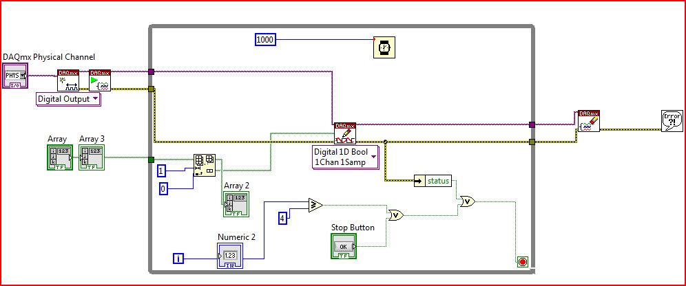
I have attached a picture of what I have so far... It is important to note that I'm finally at the entrance of the 32-bit binary strings that is why my block diagram is a bit funny. In addition, tables 2 and 3 are not something special - they are indicators.
Goozeman wrote:
Right now I use a one-dimensional array of bool to get entry. I then pop the first element of the array and write it in my DAQmx (it's essentially a queue). I put this in a loop such that it would go until the array is empty, but for some reason, it is just the first element. It is not moving to others...
Of course not. You do not update the table. Even in this case, I think that what you really want to do here is has to loop so you can autoindex on the table.
-
How can I get digital signals (interface UART) with a microcontroller with NI USB-6008?
I have acauired a few analog signals by A/D (3 channels). I put each scanned data on 3 digital output with a microcontroller. I want to see if it is possible to import these digital outputs 3 to a PC via a USB-6008? It's like the connection of the output to the digital input of the USB-6008 and import the 3 channels simultaneously to LabView? Do I need to use some other hardware like USB-8451 and connect the clock of the MCU to USB-8451?
Saraydin,
The digital I/o on the USB-6008 is a software program only, so unless your signals are rather slow, it probably will not work for you. In general, the procedure would be to connect each signal to one of the digital lines on the map and then set up a digital entry into LabVIEW task to read the three channels. If you use a device that has clocked by the digital i/o hardware, you then your input clock signal and use it as the sample for the task clock. Here is a list of USB devices supporting DIO clocked by the hardware. Also, there is an example that comes with LabVIEW, which shows how to do this. You can get to it in LabVIEW by going to help > find examples. When the example Finder window opens, navigate to hardware input and output > DAQmx > digital measures > Cont read dig Chan-Ext Clk.vi.
The 8451 is specifically for I2C and SPI, and would be great if you try to make one of these protocols, but otherwise I would recommend the devices in the list I linked above.
-Christina
-
NOR-traditional DAQ will work with a USB-6008?
Hi guys,.
I have ordered a USB-6008 and I would use it with the NOR-DAQ traditional 7.4.4 instead of MX. Is this supported?
Thank you
Jim
LV 8.6
LV 8.01
LV 7.1
TS 4.1
Jim,
No, traditional DAQ isn't USB compatible, 6008.
You can use DAQmx base instead, but I wouldn't recommend it.
hope this helps,
Norbert
-
LabVIEW think my NI USB-6008 has only analog inputs
I am using an NI USB-6008 box to run a route of analog input and analog output.
If I do a constant material DAQmx channel and out the finger tool and pull down... and it offers me 8 analog inputs on Dev1 and nothing else. I've nothing else connected to this computer, but the box USB-6008. A USB-6008 doesn't even have 8 analog input channels.
I'm a bit confused.
-
Hello
I have connected a USB-6008 to my computer, but can not read all the output using a multimeter when I run my program.
I went in the measurement and automation explorer, disappeared to the USB6008 device, click on test panels and selected the output voltage. From there, I gave different output voltages and I read all this tension using a multimeter to the USB-6008.
To check if there is something wrong with the pattern-block etc that I install, I connected the 6008 to another computer that is running labview and used the same program. It gives a very good result.
Does anyone have any suggestions as to what can go wrong on the first computer?
Much appreciated,
Paul
If I were in your shoes I download DAQ - mx 8.6.1 (here) on the PC that you are having problems with and give it a go. I don't know why the 6008 would work on a PC and not the other when they have the same configuration. Do you have other devices working on the troubled PC?
-
USB 6008 weird analog voltage reading
Hello
I use the USB-6008 to measure a voltage of a Lithium battery, 3.66V.
the battery come with a blocking diode (in series with the battery) of 1N5820, who have a fall of voltage drop of 0, 1V.
battery with diodes in series (this is the way in which the battery is shipped with)
-measure with DDM yield 3.66V without you connect to usb6008
-measure with DDM yield connected to usb6008 (putting OUT VOLTAGE USB6008) 3.59V
-able with USB-6008 performance 3.59V connected to usb6008
battery with diode removed
-measure with DDM yield 3.66V without you connect to usb6008
-measure with DDM yield connected to usb6008 (putting OUT VOLTAGE USB6008) 3.66V
-able with USB-6008 performance 3.66V connected to usb6008
Thus, it seems that the problem is in the led in the series. This is why the battery voltage has fallen to 0.07V? the series diode will hurt the USB-6008?
Maybe people who know the circuits inside the USB-6008 can give me an answer.
Thanks in advance.
Hi learnerd,.
The fall that you see is falling forward in the diode. As an entry class device, the USB-6008 case has a relatively low input impedance (144kOhm) and thus draws a little current of the device. Looking at the datasheet of the 1N5820 (http://www.onsemi.com/pub_link/Collateral/1N5820-D.PDF), Figure 7 shows that at 25 ° C, a draw of 50mA will cause a fall front of 200mV. While the figure does not extend the curve below 50mA, extrapolating the given curve would indicate that a drop of 70mV would cause only a few current microamperes.
A DMM will have a much greater input impedance (GOhms instead of kohm) and won't draw enough current to influence the measure, that's why you wouldn't see the decline with only the DMM.
The diode will not harm the USB-6008 somehow.
Good luck with your application,
The f
-
NEITHER USB 6008 voltage offset using CSR and measurement of diff.
Hi all
I am currently trying the NI USB 6008 housing and I'm getting problems when reading voltage analog using CSR or differential.
So basically, what I want to measure is a PWM signal (0 to 12V), which is divided by a divisor of tension (by two). But instead of measured 0V and 6V
I am in a position a constant 0.8V and approximately 3V.
On the side of digital data acquisition, I give you on impulses for the SSR... and it works fine.
I connect it that way: http://digital.ni.com/public.nsf/allkb/95CC0CB11D7DF3D18625712E000C4ABD?OpenDocument
Would apreciate any help
Best regards
EDIT: Attached graphics acquired are
What is the impedance of your voltage divider? The input of the USB-6008 impedance is not very high. If the impedance of the partition is large, it could cause the effect you see.
Lynn
-
Using the DAQ USB-6009 meter and an analog input voltage at the same time.
Hello
Currently, I'm reading the two channels of voltage with the USB-6009. It happens that one of the channels is the output of a digital coder, and it would be much easier to use it directly to the PFIO entry that is defined as a counter. The problem I am facing right now, it's that I can't use the DAQ Assistant to use the analog voltage to a channel and the digital channel counter at the same time. Once I put the DAQ Assistant to read the input from analogue voltage, I won't be able to add analog inputs. And as I put the DAQ Assistant to use the PFIO as a counter, I can add more entries to read analog voltage is.
I wonder if it is possible to solve this problem using the lower level data blocks? Another solution would be to read two channels in analog input voltage and that the use of Matlab to process data resulting from it, since I was not able to do the counting to work simultaneously with the acquisition in Labview to impulses.
Hope you guys can help out me.
Thanks in advance.
Using a simple wizard of DAQ is incorrect. You need one to acquire analog inputs and one for the meter.
-
Equivalent to USB-6008 with a single output channel?
I would like to integrate the features of the usb-6008 in a small package and really need a release. Is there a suitable product?
Hi Srapoport,
You are looking for something similar, but physically smaller than the box USB-6008 features? If so, I don't think we have any Renault USB which look very similar, if all small.
If, on the other hand, you are looking for something that allows you to develop your own system or enclosure box USB-6008, I would say looking at our OEM hardware. In particular, we have a USB-6008 OEM version, which allows you to integrate into your own system.
http://sine.NI.com/NIPs/CDs/view/p/lang/en/NID/202751
http://sine.NI.com/NIPs/CDs/view/p/lang/en/NID/202750Whatever it is, I would recommend contacting our sales department to learn more about what we have to offer which could meet the requirements of your application. You can find the contact information for this in the 'Purchase and quote' section on our contacts page:
http://www.NI.com/contact-us/ -
Get incremental counter/sound to work along side with action with usb-6008 with labview tia sal22
Get incremental counter/sound to work along the coast with usb-6008 with labview tia sal22
Hi all
I can get this vi to work if they are distinct from the vi but I can't join them together
Example of my error:
If buffers are set to 0 the freq counter increment works, but no sound
If the buffers are set to 1 the audio works fine but is not increment the Freq counter
If the buffers are attached to more 1 clicks and pops are comingThat's what I'm doing:
(1) have the frequency of increment of my internal sound card to a certain level as .01hz a second until he gets to 20 000 hz(2) use my device usb-6008 daq, which is connected to the same machine to measure the voltage at the same time. (I am in a position very low voltages between 1-5volts)
(3) output to a worksheet text file which will show you:
time in seconds, frequency, voltage
0,400.01,21,400.02,2.5
2,400.03,1
I'm a bit confused about how connect the increment and the audio during the measurements with the usb-6008 housing on the same machine
at the same time and in the same VI.Anyone have any ideas? I'm using labview 8.5
TIA sal22Ha ha you have been deceived by a dynamic thread. Insert a convert from Dynamic Data Express VI (Palette to own: Signal handling screw Express) between the daq read and build the array function. Then it won't work. Now the value in the dynamic data is only converted to a numeric value
-
Generate a binary sequence with the NI USB-6008
Hi all
I'm new to LabView and I am trying to generate a binary sequence with a box NI USB-6008. The sequence, I'm currently generate is a counter of 5 bits, i.e. 00000 00001 00010, 00011... 11110, 11111 placing each bit in a different digital IO of the of the 6008 NOR, so that I can use the County as the bits of selection in a decoder/demux.
I managed to simulate the binary sequence and produce a graphical interface, but I have not found how to generate the sequence of bits with the NI 6008.
Totally, I'd appreciate any help you could provide. Thank you very much.
Hi JosephM,
Good Afternooon and I hope your well today.
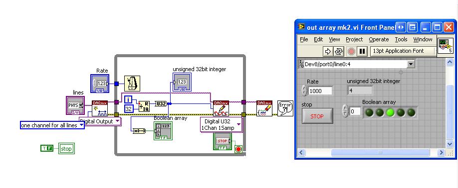
I just tested the code on a 6008 and also released the above code is very complex - I was for some reason any fixed on using Boolean tables.
Please see the attached code, in LabVIEW 8.6.
Mind you, I have configured the task as a channel for all lines. i.e. digital single I spent, is the task value should apply to all channels selected in the entry. So if you select only port0/Dev8/$line0 for example, the DAQmx driver will examine the LSB of the digital and work so $line0 must be true from the false. It will NOT update all other channels. So when I select line0:4 - it will update the first 5 lines (bits) in digital. As the code generates a number from 0-32 he emotional generates 00000 to 11111.
I hope this finds you well and sorry for the first post!
-
Data acquisition with USB-6008 using C++
Hello
I am trying to use USB-6008 to collect analog data without using Labview, since I can't afford the lincence. I searched in the C++ provided with product samples and found "Simple example of analog input.
The compiler I use is codeblocks instead of visual studio (once again for monetary reasons). The code seems to works since when I run it with the USB-6008 box connected, he wrote "gains 1000 points.
I have 3 questions relating to the use of this code:
1. where are stored the 1000 points?
2. How can I modify the code to specify the time acquisition and the frequency of acquisition?
3. How can I change this code sample points simultenously with 8 analog inputs?
Thank you for your help,
I'll try to add any clarification if necessary.
Albany
Your questions are answered in help for c programmers.
1000 points are in the variable array of points called 'data '.
The sampling frequency is set to sync.
The number of points read is defined with the function of reading.
Read channels are defined with the function channel set. To read multiple channels, use syntax such as Dev 1 / ai0:3 for the first 4 channels.
Maybe you are looking for
-
Over time, because of me hitting the keys hard, my gmail login has accumulated several misspelled usernames. Every time I have access to gmail, all pop-up. I want to clean first, but I can't get rid of them. I followed your instructions to clear my c
-
Adding a second hard drive to a 500-380nf Pavilion?
I just bought a new 500-380nf Pavilion. In the store I did understand the seller I was intending to add second hard drive to a 1 to SATA (which I already loaded with all my media files). However, now I am home and have taken the side panel, it seems
-
There is nothing in my home folder, correct bone 10.10.5. I am out of my trash in apple mail and want to go to my library/mail/mailboxes. I'm just confused? Thank you
-
Shell Lottery International, Inc.®. Is it true that they give to earn money?
SHELL LOTTERY INTERNATIONAL, INC.®. is it true that they give to earn money?
-
Why my Windows 7 will not find wireless networks?
My Dell with Windows 7 apparently tried to auto update and no not now recognizes wireless networks? I get the following error codes 80244022 8024001F, 8024402C, 80072ee2, 8024401 b, 80072efd HELP! The full convenience store is no problem?