USB-6008 to give the digital output
Hi all
I was wondering anyone at - it base an example of an exercise using USB 6008 to give a digital output of a VI in Labview.
I am very new to the use of the USB 6008 AND Assistant DAQ and so far I've had reading a temperature, next step is I want the USB-6008 to give a + 5v output when the temperature reaches a certain value, I built a Labview 2009 VI for the temperature reading, but now I'm stuck on this piece.
Any help is appreciated! or if there are examples of laboratory exercises that exist that I can perhaps draw.
Hi Marko
Please take a look at the link that has some interesting and intuitive video to use the USB-6008 housing and how to set up the device for several applications in LabVIEW below. Please take a look at the step by step videos and let me know how you go. They are under the tab '"virtual Demos.
http://sine.NI.com/NIPs/CDs/view/p/lang/en/NID/14681
Tags: NI Hardware
Similar Questions
-
Binary output to the digital output as 1111 1111 1111 pin
Hello
I use DAQ 6009 and I need output such as 1111 1111 1111, at the digital output (12) of data acquisition. Please give an idea or a vi to do
Thanks in advance...
Hi DK,.
Look through the viewfinder of the example for example appropriate screws...
In general: open/create one task DAQmx, select all lines, exit TRUE for all channels...
-
analog sync of input with the onset of the digital output
I'm trying out an analog signal to a file with a specified frequency samples. I also need a digital output to trigger a measurement at a frequency specified on a separate system. The frequency is controlled by the loop exits and timed when the iteration number divided by the period is exactly a whole number.
Both outputs work. The problem is that they are not synchronized. The analog output amounts to about 0.5 ms faster than the digital signal. (I checked with an oscilloscope) They both start in the 1 ms each loop runs for, but I really need them to start at the same instant. What can I do to synchronize? Also, if I'm going in the wrong direction complete, please indicate.
I use a card PCI-6723, which I think someone at some point, said not having a material sample clock. That's why I try to use a timed software loop.
Hi NEA.
You must use the 6723's built-in calendar to accomplish what you want. As the digital output subsystem is only clocked by the software, an appropriate solution should be to use one of the counters to the pulse output.
The attached code should show how. You can use the counter to output a pulse all samples of the AO N task. Material requires the initial delay to have a minimum of 2 ticks, so the meter will be behind the task of the AO by 2 samples in this case. There are different ways to work around this problem if you need (for example write two samples of 0 first).
Best regards
-
What is the current max on the digital output of a Terminal BNC - 2110
Im a using a card of data acquisition of 6221 with a block of connection BNC-2110 connected to it. For the e/s digital terminal block provides an additional 5V input. Unfortunately I don't seem to find any information as to know if this provides additional current to the TTL signal or no training. Is there an internal pilot in the terminal block, or - if I need to connect external relays to the digital output - always connect a current driver in between?
Thank you
Wolfgang
You can replay the 6221 and BN_2110 manual. The + 5V pins are outputs of the DAQ card - they are not entries.
Yes, you will need external circuits if the external relays require more current than can provide the DAQ card.
-
How to configure the digital output of the pci terjeta 6023E in LabVIEW 8.5?
Hi, I have a card PCI-6023E and LabVIEW 8.5 and I need is to configure the digital output on the card, but did not.
My idea is to get a port of digital data on the map and control by a pwm small dc motor.
I wonder what are the modules with which you can do.Hi skudero,
Probably the web page tracking and the attached example will work.
PWM in software timing using a digital output line
Concerning
Charley - NIB - SR 1368189
-
E/s digital USB-6008 changes when the system starts
I was intending to use the USB-6008 housing in a critical application in which the digital I/o lines are used to trigger relays. The relay should activate when I ask them programmatically. Otherwise, they must remain open. The problem is that during a reboot of the operating system, the e/s digital USB-6008 go up and down several times - opening and closing my relay. It is not acceptable for my application.
Is it possible to prevent the lines to reach logical high except if ordered to do so?
There is no way to set the startup on the 6008 States.
As the system USB boot devices and turns on power to the computer and off the power to the USB ports, on the DIO lines go up and down several times.
You will need to put a logic of material extra, just after data acquisition to ensure that potentially dangerous output combinations cannot affect the relay and the elements they control.
-
take the digital output USB-6001 always high or low in c
Hi all
I am new to the NI DAQ interface. I have a USB-6001 and I am trying to use this device to control some flowchart in C. What I want to do is:
* set digital output lines with high and low intensity and change their status as needed (in C).
I tested the device NEITHER Max--> Test panels and found that the device is capable to do that. Then I try to do in C. I have checked hace examples and function I use is one called "DAQmxWriteDigitalU32". I have problem in the understanding of its input parameters. I tried something with my own knowledge, but it does not work as I expected. Here is a test I did:
data uInt32 = 1;
Int32 wrote;
TaskHandle taskHandle = 0;
DAQmxErrChk (DAQmxCreateTask("",&taskHandle));
DAQmxErrChk (DAQmxCreateDOChan (taskHandle, "Dev1/port0/line7", "", DAQmx_Val_ChanForAllLines));
DAQmxErrChk (DAQmxStartTask (taskHandle));
DAQmxErrChk (DAQmxWriteDigitalU32(taskHandle,1,1,10.0,DAQmx_Val_GroupByChannel,&data,&written,));taskHandle = 0;
DAQmxErrChk (DAQmxCreateTask("",&taskHandle));
DAQmxErrChk (DAQmxCreateDOChan (taskHandle, "Dev1/port0/$line0", "", DAQmx_Val_ChanForAllLines));
DAQmxErrChk (DAQmxStartTask (taskHandle));
DAQmxErrChk (DAQmxWriteDigitalU32(taskHandle,1,1,10.0,DAQmx_Val_GroupByChannel,&data,&written,));I just want to set ' Dev1/port0/line7' and ' Dev1/port0/$line0"at a high level, but only ' Dev1/port0/$line0' answer me. The second parameter of the DAQmxWriteDigitalU32 function is numSampsPerChan. If I replace (currently 1) with a higher value, such as 100, I see that "Dev1/port0/line7" sends a number of 1 output, then back to 0. So I guess that the problem is just that I understand not all parameters for the DAQmxWriteDigitalU32 function. Is someone can you please tell me how I can set up a line of digital output 1 or 0?
Thank you!
Hongkun
Hello
I finally find a way to do it! The feature works very well, and my problem was not set the data value to write correctly. It seems that if I want to write a 1 to the port0/line1, I put "data = 2 ^ 1" rather than "data = 1", because by default it is the second bit of the port.» Similarly, "data = 2 ^ 7 ' high level to port0/line7. I find that this setting is surprising when you want to control an individual line. It seems more reasonable when you control the whole port. In any case, is to solve the problem!
Thanks anyway!
Hongkun
-
Configuration of the digital output in the USB-6009
I have a card for the acquisition of data USB 6009. It seems that him when DAQ card is turned on, it is always default to digital output of 'High' or 'floating '. I want to default to 'low '. Is there some setting I want to 'program' the hardware DAQ to have all the outputs low when it is powered on the value? Right now I have manually enter MAX and adjust the level 'low '. Thank you very much for your help.
Sid05,
Yes, it's low of 820 ohms. Unfortunately, the way in which the system is built, it is the only choice you have without having to build external circuits such as SnowMule suggested.
AK2DM,
Thanks for pointing the USB-6000. Finally a real, if limited, the DAQ hardware. Nevermind, he was only 4 DIO lines.
Lynn
-
How to measure the digital output of the linear actuator on USB-6009?
Hello
I am a new user of Labview and need help to measure a digital input signal.
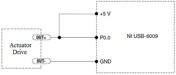
I have an actuator Bimba Original line electric with a motor continuous integrated with encoder, drive and the controller. The drive has a programmable digital output that I put as a tachometer output that emits pulses of square wave 100 per turn of the engine. I put the engine to make a total of 56 rev in 22 dry. I want to measure the speed of motor rotation labview real-time and synchronize it with a few other analog input signals. I wired the actuator for the USB-6009 case as shown below.
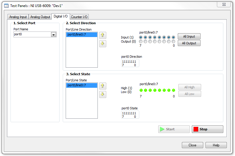
I opened the test i/o digital USB-6009 Panel and fix all the lines of port 0 as inputs. However, when I click on start and run the actuator, p0.0 led flashes, as indicated below.
Shouldn't the led blink in response to revolutions of engines?
I want basically to collect the drive pulse signals and convert them in rpm on labview.
ahsan2 wrote:
I have it wired correctly?
It would help if you do not attach the HIGH signal. Remove the + 5V in the circuit.
-
Is it save to use the digital output as a digital input for another channel signal
Hi all
I know it's a stupid question, but I don't have another generator of signals by hand. What I want to know is, can I use the signal digital output of my USB-6001 as an input for the same signal device, but on other digital port? I wasn't directly because I don't want to burn the device...
Thank you
Done all the time. No problems.
-
FPGA CRio do not give good digital outputs
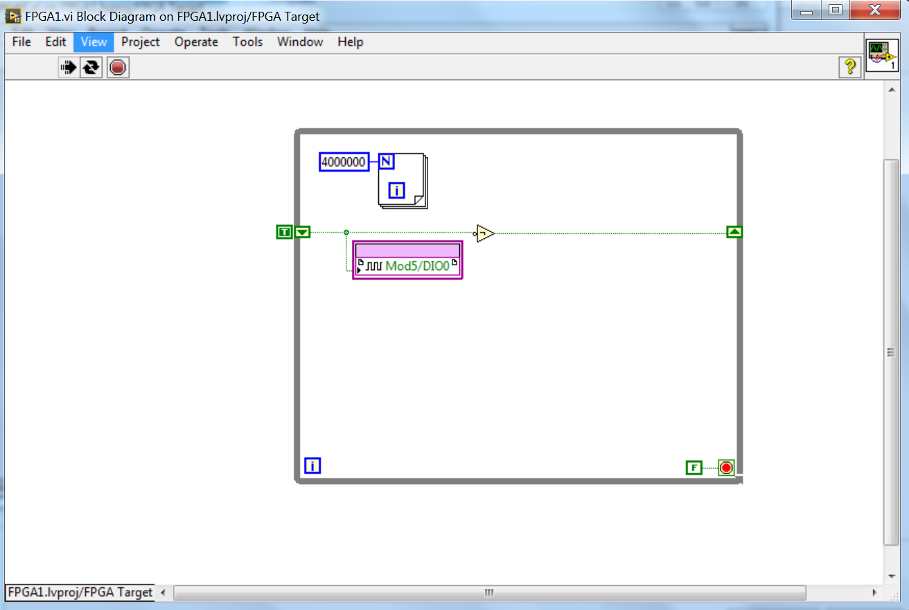
I'm working on a project with the compact RIO fpga. I tried following the youtube tutorials and written tutorial, but I get no similar results in scanning FPGA interface.
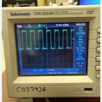
I have attached my project. Here's the signal that I get from the Basic VI, which is a digital IO defined as output in a while loop. Alongside this, there is a loop for fundamentally changing the frequency of the digital signal from the top down. But whatever number I put in the loop for, it gives me the same frequency.
My thought process goes like this: If the CRio has a processing time of 40 MHz to a loop that cycles 400 times should give me a swing of 100 kHz output, which is not any number, I put in.
Any help is appreciated.
Thank you.
LabVIEW is almost certainly that compile to loop out like dead code (nothing happens so LabVIEW gets rid of it). I advise to use the loop timer function if you are looking to change the frequency or put everything in a timed loop. All in a timed loop will execute a tick.
-
I use a PCI-MIO-16-1, and I'm trying to create pulses on each of the three digital outputs, using a hardware trigger. I got a solution that sort of market by using a loop timed; the loop runs once per trigger, and inside the loop, I use avoiding to turn each of the three outputs at the right time.
However, the problem is that the 1ms resolution of the timing of software is not good enough. So I try to find a way to do it using equipment, so I can get a finer resolution.
What I tried to do recently is to create a redeclenchables on one of the counters pulse train (using the example generate digital Pulse Train-finishes-redeclenchables) and use it as a trigger for the timed loop. I can get the pulse train to give me three ticks for every time that I get a hardware trigger and then put a state machine inside the loop to turn each of the outputs. (I am currently divide the material into three equal segments trigger.)
However, although I can generate the pulse train very well on one of the counters, I can't manage to get the timed loop to use this counter as its source of the moment. How can I do? Or does anyone have a better idea how to do that?
Unfortunately, the card you have does not allow for hardware timekeeping DIO. M series and recent X series Multifunction DAQ devices allow such a task. If you want, I can have a technical representative contact you to discuss your request and provide appropriate suggestions to optimize your application.
Kind regards
Glenn
Technical sales engineer
National Instruments
-
Acquire the values only when the digital output is high.
Hello
I work with test of transistor, whose door is controlled by the digital release of USB6289, related to BNC2120.
Test plan:
Door 1.transistor is enabled for 5seconds, with P0.0 for example
2. then, everything remains off for 1secondes.
3.p0.1 is used as digital output to activate the circuit passing him curent through in the opposite direction, P0.1 goes high for 3 seconds, PS: Gate is off.
4. the same cycle repeats again.
My question is to store values to the output of the transistor when P0.0 and P0.1 goes high, and these values should not change until my digital outputs respective again go high.
I can access transistor by continiously read out my power supply values.
and in the State off I want to read AI0 because at that time, my power supply is off, so that I can activate the circuit to pass the current in the opposite direction.
Again, my question is to gain the output through power value when P0.0 is high and store them until the transistor turns on.
and even for P0.1, acquire the value of output through AI0, when P0.1 is high and store it until it goes high again.
Hopefully, I'm able to explain my problem clearly.
Please help me.
Concerning
Anurag
Think about what States (object:statemachine and determine when to use sequence Structures) do you want from t0... t(n-1), IF DAQmx generates outputs and/or inputs are absorbed and what needs to happen (event timed out), before move you on to the next 'State '.
type def 'enum' with your different States:
- initialize
- wait (the user initializes times (sec) set for States, or whatever and presses button 'Start')
- T0 (generate DigOutputs, store acquired data AnalogOutput (string output number) the register shift, before moving to the next State > user 'set time' must elapse (Note: the wait function allows you to control the rate of execution of loop and allow the CPU to respond to external events and system tasks and avoid using wait functions at the same time an operation of software...))
- ...
- t(n-1) if ' end (made requirement) "> goto 'stop', ' another (not requirement not)" > goto regardless of 'State '.
- stop
- write a text file of data (string).
-
Manchester in transmission/reception of signals using the digital output of the PCI-6224
How a manchester signal can be sent and received using the OID of the pci card 6224?
I want to create a signal NRZ manchester on a digital output channel and then have the possibility to receive and interpret the same type of signal on a digital input channel.
Any help would be greatly appreciated.
Hi VJohnson,
You might find this post of discussion forum useful.
Looks like LabVIEW has not Manchester coding/decoding built, but do able in your VI by replacing all the elements with the corresponding elements of two and using double the speed of transmission as your clock frequency.
Thank you
Scott M.
-
How to generate the digital output of the variable duty cycle and clock source being contrary?
I want to generate a digital pulse every front amount of my pulse counters. He must have a variable duty cycle. until now, I've been able to generate a digital output, but I can't change its duty cycle.
pls tell how I should proceed?
Thank you in advance...
Maybe you are looking for
-
Satellite A660-1CJ - 8.1 Windows crashes - BSOD bridge.sys
Hello I have a Satelite A660-1CJ, running Windows 8.1 and he already broke 5 times with a BSOD:DRIVER_IRQL_NOT_LESS_OR_EQUAL (bridge.sys) What can I do?
-
Hello I bought a T61p in 2008 and it has been running very slow for some time, especially the start-up took about 10 minutes and my Office crash applications constantly. Yesterday, I finally took the time to reinstall Windows Vista. Now, it's faster
-
Z10 Z10 blackBerry won't save files!
If someone has experienced this problem or I'm doing something wrong. I tried to select a file, selected the option to save, renamed the file and choose a location and then click Save. When I return to verify that it was registered, found nothing, I
-
Saving a project on a flash drive problemst
I try to save an entire project of 2 hours in MPEG format on a flash drive to a customer. I've never had to do before. I tried several times at different levels of resolution, but the encoding process hangs or crashes. What is the best resolution
-
HelloI just start learning how to animate CC. In the section 'Use of step' PDF Manuel help user, it refers to "Option contained in FT-wide" could someone tell me what does "IP"? -J' thought it might mean "Program Interface", but I'm not sure.Thank yo