USB-6009 software simultaneous timed output analog
Ladies and gentlemen,
I worked on a LabVIEW interface to a potentiostat I designed and built. I'm not very experienced with LabVIEW, but do they have experience with a variety of other languages (I had originally intend to use an FPGA for this, but he has been asked to write a LabVIEW VI first) programming.
The goal:
I want to output a voltage (initially consisting of ramps) signal and measure the voltage with an operational amplifier configured as an ammeter of feedback (using resistance feedback and voltage value to calculate current) connected to an electrochemical cell. The resistance of feedback is selected by using an automatic selection function (although I wrote a version prior to manual control) as TTL values using the DAQ Assistant to select relevant MUX channel outputs. I then try to save the data in a spreadsheet.
The problem:
I use an acquisition of data USB-6009, and I know that there is a hardware clock. Read all about him seemed obvious, the best way to the waveform of the output voltage used DAQmx package to define a function of writing in a loop that is clocked by the software. The problem I have is that I can't synchronize the output to the input with reliability and I have also some errors related to resources DAQ being reserved (error 50103). I think the way to solve this would be to convert every equivalent DAQmx DAQ Assistant and try to group their execution - this is where I fall. I tried to write a simple VI who shared a loop clocked by the software to read and write but had problems related to the value of min HAVE (error 200077).
General issues:
How I begin the process of read/write (with a Boolean switch) is very weak and doesn't feel not robust. Ideally, I would like to some form of indicator to warn the user when the read/write process is running and when it ended.
My error handling is terrible, but I find no big thing to read about the basics.
I use only a sequence of no and I think I should have more.
Once I hit the beginning, VI requires the file name for the worksheet - at first, I was afraid that data would be entered correctly, but I think it's okay because the file is generated and then changed. It would be better if the user asked for the name of the file once completed the data collection.
Any suggestion or help would be greatly appreciated. Thank you in advance.
Sincere greetings,
Julius
The hardware supports timed 6009 entry analog. Even with the 1Samp mode, your code could be simplified with a single task and several channels (dev1\ai0:1). Then use Nchan 1Samp.
Tags: NI Hardware
Similar Questions
-
USB-6212: software problem timed task of analog input
Hi all
I have unexpected behavior using a USB-6212.
The code example shows that when I run in sequence two analog DAQmx to task, material entry first a timed, the second software timed, it happens that the first readings of data are all wrong and have the same value for all channels.
The labour code is the following:
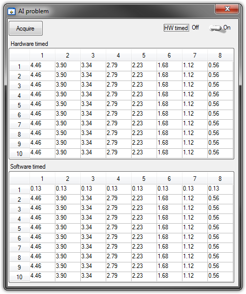
   GetCtrlVal(panelHandle, PANEL_HW, &Switch);

    if (Switch) {
//
// First Task: read 10 rows of values with hardware timing
//
        DAQmxCreateTask("", &htAI);
        DAQmxCreateAIVoltageChan (htAI, MX_DEV_AI, "", DAQmx_Val_NRSE, -10.0, 10.0, DAQmx_Val_Volts, "");
        DAQmxCfgSampClkTiming(htAI,"", SAMPLE_RATE, DAQmx_Val_Rising, DAQmx_Val_ContSamps, 1000);
        DAQmxRegisterEveryNSamplesEvent (htAI, DAQmx_Val_Acquired_Into_Buffer, SAMPLE_RATE, 0, RefreshCB, NULL);
        DAQmxStartTask(htAI);
            Delay(1.0);

        DAQmxStopTask(htAI);
        DAQmxClearTask(htAI);
    }
//
// Second Task:read 10 rows of values with software timing
//
    DAQmxCreateTask("", &htAI);
        DAQmxCreateAIVoltageChan(htAI, MX_DEV_AI, "", DAQmx_Val_NRSE, -10.0, 10.0, DAQmx_Val_Volts, "");
        DAQmxStartTask(htAI);

    for (i=1; i<=10; i++) {
        DAQmxReadAnalogF64(htAI, 1.0, 10.0, DAQmx_Val_GroupByChannel, AcqVoltRow, HW_AI_CHANNELS, &read, 0);
        SetTableCellRangeVals (panelHandle,PANEL_SOFT, MakeRect(i, 1, 1, HW_AI_CHANNELS), AcqVoltRow, VAL_ROW_MAJOR);
        Delay(0.1);
    }
    DAQmxStopTask(htAI);
    DAQmxClearTask(htAI);
A picture is worth a thousand words: analog inputs have been connected to a network of resistance have known values.
The upper table contains timed material acquisitions, the lower the software timed readings... as you can see it the first line is the set of values of 0.13, totally wrong
If the task of timed acquisition of software runs without the earlier (in my demo, that this can be achieved by the switch at the top right), the readings are correct!
Y at - it something I am doing wrong?
I also tried to run the program on USB-6009, but it seems to work properly.
[LabWindows/CVI 2010 SP1 - driver OR-DAQmx 9.4 - Windows 7 x 64]
This problem was corrected by NOR-DAQmx 9.5
324044 NOR USB-621 x task HAVE request returns incorrect data after erasing a task HAVE stamped
-
How to ±2.5V AO of NI USB-6009
NI USB-6009 data acquisition manual, the analog output is 0 - 5V.
I somehow puet - 2, 5V to 2, 5V analog output? Can be fed - 2, 5V to GND analog to voltage?
Thank you.
H, Dennis,
I'm afraid, you can do so with an external circuit
as I see it, the minimum components are:
-two double-power supply rail-to-rail amplifiers
-a 2.500V reference voltage
-a supply - 5V negative (for example a small + 5V/5V converter DC/DC, ICL7660)
-five precision resistors
Pros
-
Digital and analog inputs simultaneously - NI USB-6009 and NI USB-6212 - ANSI C
Hello
I'm reading at all times and at the same time analog and digital inputs. Digital and analog samples must be sampled at the same clock and acquisition should be started (triggered?) at the same time (I don't want, after some time, analog reception more digital samples - the opposite is also true).
I found an example (in C source code) "National Instruments\NI-DAQ\Examples\DAQmx ANSI C\Synchronization\Multi-Function\ContAI-Read dig Chan" and tried to run with two USB cards: NI USB-6009 and NI USB-6212. Unfortunately, the two results by mistake, as described below:
DAQmx error: the requested value is not supported for this property value.
Property: DAQmx_SampTimingType
You asked: DAQmx_Val_SampClk
You can select: DAQmx_Val_OnDemandTask name: _unnamedTask<1>
State code:-200077
End of the program, press the Enter key to exit-Is it possible sync analog and digital acquisition in the paintings?
-If so, how?
Thank you
Hello tcbusatta,
Two of these modules, USB = 6008 and USB-6212, support only timed software inputs and digital outputs. This means that you cannot define material timing (like finished sampling or continuous) for these modules. Digital lines can be retrieved or written once to each call DAQmx read.
This means that you will not be able to get any type of synchronization tight between the analogue and digital channels. You will need a Board such as the NI USB-6341 in order to synchronize the AI and DI closely.
-
Output analog, the USB-6009 case - can I use DAQmxWriteAnalogScalarF64?
I just got a NI USB-6009 and I try to use the outputs analog simple.
I'm running on a Mac, so I'll try to use the API OR-DAQmx Base 3.2 C (downloaded from here: http://joule.ni.com/nidu/cds/view/p/id/1078/lang/en). This is the most recent version of NOR-DAQmxBase, I could find.
I try to do continuous analog output on the 6009, which does not have a built-in clock. I was hoping to do the sync software and just new output values when I want to.
I can't get an output of database to work. Other messages and the example of Windows files, (e.g., National Instruments/NOR-DAQmx Base/examples/ao/MultVoltUpates-SWTimed.c) it seems that the best thing to do would be to use the DAQmxWriteAnalogScalarF64 function.
However, this is not in the Mac version of the C API of NIDAQmxBase. There is actually an entry for this in the NIDAQmxBase.h file, but it is commented out. Anyone know why? Is it possible to use this function for the analog output on request on Mac?
Thank you.
Clement
I have NEITHER-DAQmx Base installed 3.2 on a 10.4.11 system. One of the examples files 'genVoltage.c' calls DAQmxBaseWriteAnalogF64. I was able to compile and run this example with a USB-6009.
The DAQmxBaseWriteAnalogF64 function would work for you?
My guess is that, since you can write a scalar value with DAQmxBaseWriteAnalogF64, DAQmxBaseWriteAnalogScalarF64 becomes superfluous. The example provided with the installation shows how to write a unique value (i.e. scalar.). I pasted the code of OR below.
int main (int argc, char * argv [])
{
Task settings
Int32 error = 0;
TaskHandle taskHandle = 0;
char errBuff [2048] = {'\0'};
Channel settings
Char [] = "Dev1/ao0" chan
float64 min = 0.0;
float64 max = 5.0;
Sync settings
uInt64 samplesPerChan = 1;
Writing data parameters
float64 data = 3.25;
pointsWritten of Int32;
float64 timeout = 10.0;
DAQmxErrChk (DAQmxBaseCreateTask("",&taskHandle));
DAQmxErrChk (DAQmxBaseCreateAOVoltageChan(taskHandle,chan,"",min,max,DAQmx_Val_Volts,));
DAQmxErrChk (DAQmxBaseStartTask (taskHandle));
DAQmxErrChk (DAQmxBaseWriteAnalogF64(taskHandle,samplesPerChan,0,timeout,DAQmx_Val_GroupByChannel,&data,&pointsWritten,));
Error:
If (DAQmxFailed (error))
DAQmxBaseGetExtendedErrorInfo (errBuff, 2048);
If (taskHandle! = 0) {}
DAQmxBaseStopTask (taskHandle);
DAQmxBaseClearTask (taskHandle);
}
If (DAQmxFailed (error))
printf ("error in DAQmxBase: %s\n",errBuff); ")
return 0;
}
Hope this helps!
-
inputs and outputs analog digital usb 6009
I'm having a problem with my USB 6009 in labview programming. I try to read continuously from the analog inputs while having an event focused on digital output within the same program/vi. Basically, I need to taste all the time the analog inputs while having an event defined by the user (button control) to signal the digital inputs to turn on then after awhile. The event of digital output must be independent of the analog sampling system. I was throwing the "error already allocated resource" in most of the vi, I wrote to try to achieve. What is programmatically possible with usb 6009? I am at my wits end trying to do this and any help would be greatly appreciated (by myself and my boss). Thanks in advance for your answers.
RJ
-
Timed software a generation of impulses - USB-6009
Hello.
I searched for a reliable way to produce a pulse point by point with the USB-6009. My question is whether or not it is possible to produce such a signal without hardware timing or a counter as the USB-6009 supports neither. Is the closest I've come to produce a square with a very low duty cycle wave. However, what I would ideally look for is the ability to produce a single pulse inside a loop which I can go once per minute or more. Also, I would like to know what are the parameters I would be sacrificing to produce a pulse in this way.
I also have access to a function generator and as it seems quite difficult I will be probably triggering just its pulse function in the same way, but I'd like to explore this obstacle before moving on.
Thank you
Travis.
20 ms can enter the region where you will begin to see significant amounts of timing jitter. You really need to write your program and make some careful measurements - over a long period of time - to see how much of a problem you will have. Actual performance will depend on a lot of details: the operating system, other software process running in the background, and how the LV program is implemented. You must reduce as much as possible, everything else on the computer: no network, no antivirus, no Bluetooth or WiFi connection and so on...
Lynn
-
Hello guys,.
I am trying to create a simple VI to generate two outputs analog square with USB-6009. Each output supplies a LED and it is necessary that single LED shines at the time - so when Out0 is active, Out1 is zero and the other way around.
To get started, I created a VI in which the goods are made manually by Boolean and it works fine (square v1.vi of signal).
But I need the output to switch automatically after the amount of time given (I needn't of high frequencies, at about 1 Hz). To do this, I changed "square wave v1.vi" in "square wave v2.vi" and set the Structures of the case in an another While loop which would be timed by the wait function (ms). The idea was that the loop internal would turn the output rate of frequency while the outer loop would ensure a continued implementation of the programme. But the reality is very different and my low level of competence (this is my first VI) let me down. Could you please help me out of this? I appreciate all the advice.
To summarize: The VI must be continuously running program that generates two dependent signals with adjustable amplitude and opposite phases (Out0, when active, Out1 is zero and vice versa.). Signals must be switched automatically to the given frequency.
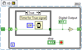
Here's a simple flip-flop - while time the loop runs, the Boolean line connected to the digital output passes from true to False to True... with the schedule determined by the time you put in waiting for him (note that you can have regardless of the different times for the true = on and False = off case). Of course, the life of signal (represented by 'Digital output') 'inside' this loop - you have to put the 1 point 1Line DAQmx VI write digital Boolean inside the loop, or find a way (for example, a queue) to get the data between the inside and outside.
-
Using the DAQ USB-6009 meter and an analog input voltage at the same time.
Hello
Currently, I'm reading the two channels of voltage with the USB-6009. It happens that one of the channels is the output of a digital coder, and it would be much easier to use it directly to the PFIO entry that is defined as a counter. The problem I am facing right now, it's that I can't use the DAQ Assistant to use the analog voltage to a channel and the digital channel counter at the same time. Once I put the DAQ Assistant to read the input from analogue voltage, I won't be able to add analog inputs. And as I put the DAQ Assistant to use the PFIO as a counter, I can add more entries to read analog voltage is.
I wonder if it is possible to solve this problem using the lower level data blocks? Another solution would be to read two channels in analog input voltage and that the use of Matlab to process data resulting from it, since I was not able to do the counting to work simultaneously with the acquisition in Labview to impulses.
Hope you guys can help out me.
Thanks in advance.
Using a simple wizard of DAQ is incorrect. You need one to acquire analog inputs and one for the meter.
-
OR USB-6009 with op-amp to amplify the analogue output
Hello.
I use an NI USB-6009 data acquisition to send a signal to a proportional pressure regulator which varies the pressure of pneumatic system. Unfortunately, the controller of pressure requires a signal of order analog 0 - 10V and the 6009 can 0 - 5V.
So I thought I'd build a small circuit with a gain of 2 to amplify the signal. See photos attached to a schema and the picture of the installation. The 741 operational amplifier is powered by a 24V DC power supply. 24V is a bit on the side high to the op-amp but I have this supply already built in and (using a supply of laboratory bench) the circuit works exactly the same in 12-18 v.
Bascially, with voltages of entry of 5 up to 2 volts, the circuit behaves perfectly. The output is just the input multiplied by two.
However, the output is never less than 3.9 volts (ish), regardless of the input voltage.
Can anyone suggest a solution (or know where else to ask)? I really need to be able to control my production within the range of 1 - 10V.
Thank you very much. John
Yes, a LM358 should work. You will not be able to get all the way up to 0 v, but it should get you up to 0, 5V or almost. The LM358 is a dual op amp, then you will not be able to deposit into the same outlet as your 741. You can probably get away with leaving half disconnected unused. (Which is not true of all double operational amplifiers).
Chris
-
How to measure the digital output of the linear actuator on USB-6009?
Hello
I am a new user of Labview and need help to measure a digital input signal.
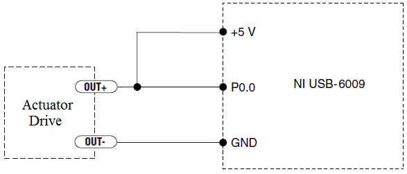
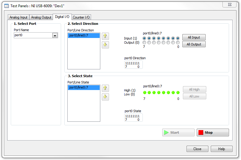
I have an actuator Bimba Original line electric with a motor continuous integrated with encoder, drive and the controller. The drive has a programmable digital output that I put as a tachometer output that emits pulses of square wave 100 per turn of the engine. I put the engine to make a total of 56 rev in 22 dry. I want to measure the speed of motor rotation labview real-time and synchronize it with a few other analog input signals. I wired the actuator for the USB-6009 case as shown below.
I opened the test i/o digital USB-6009 Panel and fix all the lines of port 0 as inputs. However, when I click on start and run the actuator, p0.0 led flashes, as indicated below.
Shouldn't the led blink in response to revolutions of engines?
I want basically to collect the drive pulse signals and convert them in rpm on labview.
ahsan2 wrote:
I have it wired correctly?
It would help if you do not attach the HIGH signal. Remove the + 5V in the circuit.
-
USB-6009 slow output signals using SignalExpress - error 200077
We have a Council of USB-6009 and Signal Express version 3.5.0
We want to generate low-frequency, analog and digital outputs to simulate some slow movement process.
We have created the signals and their generated as output, put when we RUN the project, we get error 200077, which seems to indicate that we must use On Demand distribution of signals.
If we choose On Demand, then the generate DAQmx says we have a missing entry.
So, what method should be used with the slow USB-6009 to generate box (.01Hz and slower) analog and digital outputs?
These are 2 of the projects, we tried - using On Demand, N samples, continuous, internal, and external triggering etc..
Thanks adavance for your help...
Welcome to the forums of Steve,
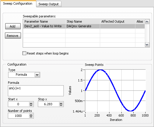
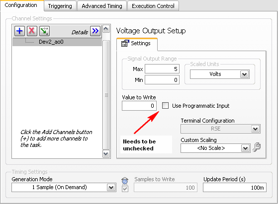
I have good news for you. I played a bit with the sweep and actually got a code facing up to generate a slow signal. I went and tested it with the 6009 and he was able to run without any errors. I joined here, but if you have to open (or anyone else in the future), here are some screenshots of how it works. If this works, feel free to make the forum as resolved while others can locate a solution a little easier in the future.
Scan Configuration:
DAQmx Config:
-
With the NI USB-6009 analog input lag
Hello
I try to acquire analog signals with NI USB 6009 using LabVIEW. (The signal is 50 Hz of the functional generator).
However, the acquired singnal has dynamic splitters, which is NOT observed by my oscilloscope.
I have no idea why this phase shift occurs.
Any information is welcome. Thank you for reading.
An image file will not help. Post your real VI. If Firefox does not work, use explore or Chrome to fix your VI (s)!
You have here a Subvi, I don't see what's inside and how it is configured. In addition, this while loop is ridiculous: there is no button to stop him running. Never use the red button to abandon for a normal shutdown of a VI!
Why you have configured NChan NSample? Measure a unique signal, Yes? For example, use 1 channel only.
Edit: why do not you play first with an example given, delivered with LabVIEW?
Your LabVIEW, go to the Help menu--> find--> material and output examples--> DAQmx--> entry--> and open 'Input.VI - constant tension!
This VI allows to enjoy your analog signal.
-
DAQmx also write Analog DBL 1Chan 1Samp down of released NI USB-6009 - code error-200077
I'm trying to get 5V 0V high low output of ao0 to an NI USB-6009 based on a switch in LabVIEW using DAQmx writing Analog DBL 1Chan 1Samp.
When you use a voltmeter connected to ao0 and analog-ground on NI USB-6009; Im not getting anything.
I also get code error-200077 for some reason any:
DAQmx Start Task.vi:4
Property: AO. Max
asked the value: 10.0
Valid values begin with: 0.0
End with valid values: 5.0Channel name: Ao0/Dev1
The task name: _unnamedTask<28425>
Set the configuration output terminal to the CSR instead of by default.
Five maximum value and the minimum value to zero.
See attachment.
-
Current output digital USB-6009
Hi, I'm trying to increase the voltage output digital device USB-6009. I read a few topics on the use of a relay, but I couldn't get it.
I was thinking of using power 5V on the map because there current 200mA on it, but when I use it with open-collector output, it cannot change the relay. When I measure the current between
5V and ground: 200 ma,
5V output, I read a value around 30-40 my.
Why can I not use this 200mA with output? It is the Relay that I use.
If this is not possible, can I use an external power supply 5V (with more current) and a digital output to pass the baton without damage the 6009?
Outputs digital of the USB-6009 confined to 8.5 my. Your relay coli requires much more than that. Even if the power source can provide enough current for the relay, digital output can not put.
The solution is to use a buffer of extermal. The ULN2003 can switch currents up to 500 my and voltage up to 50 V while being controlled by digital output.
Lynn
Maybe you are looking for
-
Start - option from menu on Portege R200
The Toshiba Portege R200 has a boot menu option? I tried F12 and C and nothing happens. The only way I've found is to change the boot priority in the BIOS. Thank you, Rob.
-
I installed both and I tried the 32-bit and 64-bit windows 7, but sometimes when I open my PC and as in counter strike source or any game if lag as if I m having spikes and all my fps and latency and ping is fine its just windows 7 or something I don
-
Windows live mail menu bar missing
the small square beside icon of the "?" is missing in WLM, so I don't see a menu drop-down uncheck Hide menu bar. How can I activate the menu bar (file, edit, view, Favorites, tools, help) in wlm? only at home, records, reviews, accounts is visible o
-
Which hard drive buy for my laptop Toshiba Satellite 15.6 "3 GB HD 320?
After receiving an error of 10-FA12 - 054D and do not recover my laptop to zone out, I believe that I have to buy a new hard drive. Which hard drive buy for my laptop Toshiba Satellite 15.6 "3 GB HD 320?
-
Raises an exception if the cursor failed
Hi, how can I write an exception if a cursor was unable to retrieve the values in the variable? for example, I have 10 cursors in procedures from my store and I want if this cursor was not able to process then threw an exception. For example, code be