USB-6211 - digital output not supported?
Hi all
I can't use the USB6211 device port... I use daqmx with Delphi7 API functions.
First of all, I tried this:
DAQmxCreateTask('', @TaskDO);
DAQmxCreateDOChan (TaskDO, PChar('Dev1/port0'), ", DAQmx_Val_ChanForAllLines);
DAQmxWriteDigitalU8 (TaskDO, 1, 1, 1, DAQmx_Val_GroupByChannel, $FF, @written, nil);
I had an error in the DAQmxWriteDigitalU8:-200012 (= digital output not supported). (???)
OK, I tried to disable autostart option based on DAQmxWriteDigitalU8 and insert a 'manual' start in the code:
DAQmxCreateTask('', @TaskDO);
DAQmxCreateDOChan (TaskDO, PChar('Dev1/port0'), ", DAQmx_Val_ChanForAllLines);
DAQmxStartTask (TaskDO);
DAQmxWriteDigitalU8 (TaskDO, 1, 0, 1, DAQmx_Val_GroupByChannel, $FF, @written, nil);
DAQmxStopTask (TaskDO);
Now, I got the same error in DAQmxStartTask:-200012 (Digital Output not supported, once again). (?????)
I don't understand.. 'Digital output not supported "? USB-6211 has 4 lines! What is the problem?
I want to just turn on and off the lines from code...
-Cs George-
Well, finally I figured out...
Here is the solution:
DAQmxCreateTask('', @TaskDO);
DAQmxCreateDOChan (TaskDO, PChar('Dev1/port1'), ", DAQmx_Val_ChanForAllLines);
DAQmxWriteDigitalU8 (TaskDO, 1, @dummy, 1, DAQmx_Val_GroupByChannel, @bitmask, @written, nil);
Digital output lines are on port1! Corrected parameter.
And the part of the interface of DAQmxWriteDigitalU8 had to be changed (in nidaqmx.pas).
I don't know why, but the AutoStart (dummy) parameter in the DAQmxWriteDigitalU8 function is ignored: function always starts task automatically, regardless of the value of autostart. But this isn't a problem for me.
-Cs George-
Tags: NI Hardware
Similar Questions
-
Pull-up external USB-6009. digital output (open collector) allows onboard external + 2.5 V output?
Pull-up external USB-6009. digital output (open collector) allows onboard external + 2.5 V output?
Hello
I want to config output digital USB-6009 to + 2.5 V above and 0 V digital output low. I know I can config USB-6009 digital output open collector with resistance to pull-up external, that can be applied with + 2.5 V power source.
My question is: can I use USB-6009 Board + 2.5 V output as the current source of resistance to pull-up? What resistance is a good number for the resistance to pull-up, if I can use this configuration?
Thank you much for the help.
Cathy
Hi Cathy,.
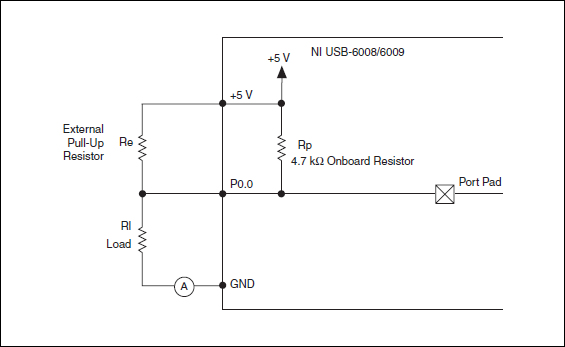
The digital USB 6008 front-end server looks like this:
So, there is actually an internal pullup to 5V 4.7 kOhm resistance when the device is configured to open collector.
If you want to display 0 to 2.5 V, I would look in a resistance of polarization of 4.7 kOhm between c and ground (according to the rest of your tour).
Best regards
-
Ive got an acquisition of data USB-6211 (and LabView 2009) and Im trying to get the output (5v) device to run a relay on and outside. IM using a tutorial I found on Internet to make the diagram Labview (http://www.pages.drexel.edu/~pyo22/mem639/lab-usb6211DigitalInputOutput/lab-usbDigitalInputOutput082...) and the circuit is simple. I tried to run the DAQ Assistant to test if my output was working, and it is not. I'm not sure if my connections for data acquisition are correct or not. Any help would be useful.
Thank you.
Hello NT_Mech,
Indeed, it is possible that you do not drive enough current for the relay. You can check the specifications of your USB-6211 and see that the digital line will result in a maximum of 16mA. That being said, your relay control current that is needed, you may need to run the two outputs in parallel to offer twice more common provided. Recently, I drove a Soviet Socialist Republic of a Luminary Micro Prototype Board that did not provide enough current as well. In the case of the tat, I was driving the relay by running two lines in parallel.
You can always simplify the software side of things by opening the measurement and Automation Explorer (MAX) and right click on your device and select test panels. "" ' Start ' programs ' National Instruments ' Measurement & Automation then expand devices and Interfaces. Right-click and select Test panels. You can then configure a digital output for your USB-6211 and toggle On / Off and check out.
Best,
-
NI USB-6009 digital outputs are active when connected to a PC - I'm not that
I have a small problem:
All outputs digital NI USB-6009 module become active when the module is connected to a PC when no VI is running.
As soon as I start my VI, which controls the module, all the outputs are disabled (now inactive).
How can I achieve this, outputs are inactive if the module is connected to a PC with no program running?
johanneshoer wrote:
I have a small problem:
All outputs digital NI USB-6009 module become active when the module is connected to a PC when no VI is running.
As soon as I start my VI, which controls the module, all the outputs are disabled (now inactive).
How can I achieve this, outputs are inactive if the module is connected to a PC with no program running?
The USB-6008/6009 case has a pull-up internal (4.7 kOhm) resistance. This causes the outputs digital on the device to have a startup logic high State. t is not recommended to use some sort of resistance of menu drop-down. However, what you can do is add octal buffer like the 74HC541 stamp and a digital output to control the sorting of the 74hc541 state mode. Connect the OAS and CEO input signal. A Summit on the pins of the latter will be sorting the output of the buffer State. Therefore, no output signal will be present until you pull the stems of low control. The USB-6008/6009 case have a 5 volt output (200mA max), you can use the buffer.
-
NI USB-6501 digital output problem
Hello
I use DASYLab v.11 and I'm working on an interface with the NI USB-6501 where I'm putting a digital high on four ports.
With the module "NOR-DAQmx - digital input", I managed to read the digital inputs of the ' NI USB-6501 ".»
It's only the "NOR-DAQmx - digital output" I can't go to work.
Using 'NI MAX' of NOR I have easily can emmit my four LEDs in the way of my High/Low ports.
But not with DASYLab. When you use DASYLab tension on the ports remains unchanged.
Now, I have a switch module, generating 5/0, directly connected to the digital output module, which is assigned to my four output ports for my task.
I also tried with a module of relay between the two without success. I also tried to use 1.5 above instead of 5 without success.
I use the option 'Bus (0/5 supply) for the module "Digital output".
"NI Max", I configured the ports as "active drive.
Any suggestion of what I might be missing?
Thank you
Martin
Hmm, four ports, or four lines?
A port consists of eight lines. Each line can control an LED (ON / OFF ~ 0/5V).
If you have created a task to dig-out to control a port, 5V to this port sending sets all lines of this port to 'high '.
You need to 255 for each line one too high port (at the bit level: 128 + 64 + 32 + 16 + 8 + 4 + 2 + 1).<- eight="">
Or, you can create a dig out tasks to control four lines of a specific port.
Four lanes of the EEG DAQmx DigOut module.
Each of the channels of the modul will feed a single line of the task/device.
Four switches will then turn the lights, or turn off.
Make sure, that the 'bitposition' is the number of correct line (see picture).
-
USB 6008 digital output signal
I am VERY new to LabView and have been racking my brain trying to get digital output of my USB-6008. All I want is to be able to get a signal of + 5 V of my digital output when I click on a button. This signal opens a valve on a system I see so when it is pressed, it must stay open until I press the new button. It seems simple enough to me, but I'm not too familiar with LabView. Help, please!
Stripling07
You must first take the LabVIEW tutorials and then look at the links to get started with DAQmx .
The simplest program would be with the DAQ Assistant. Drop it on your schema, and then select digital output > digital line. Select the line when the wizard has completed, click OK. Wire a Boolean value in a table to build and the output of which is connected to the data entry. That's all. You can test the output of MAX (Measurement & Automation Explorer) with the test Panel. Do NOT test with your connected tap. Your valve may require more current that can provide the 6008.

-
I have a VB6 program with code that correctly reads the analog inputs of a NOR-USB-6008.
I tried to re - use the code in a module of extensometer OR-USB-9237, but at the stage of DAQmxCreateAIVoltageChan, I get the following error:
"Measurements: physical channel selected does not support the type of measure required by the virtual channel you create."
Create a channel to a type of measure that is supported by the physical channel, or select a physical channel that supports the type of measure. »
Should I call one function other than DAQmxCreateAIVoltageChan?
If so, what is it, or where can I find the reference for these functions?
Or - if it of the right function, should I pass different arguments? Currently, I'll call you:
DAQmxErrChk DAQmxCreateAIVoltageChan(taskHandle, "Dev1/ai1", "", DAQmx_Val_Cfg_Default,-10, 10, DAQmx_Val_VoltageUnits1_Volts, "")
Thanks in advance for your help
-Alas
I thought she 372251a. PDF
Firstly, the correct function is DAQmxCreateAIVoltageChanWithExcit
Second, you can't just ask for a sample single channel - ask for 2 samples instead.
-Alas
-
Toshiba 40L7335D - USB NTFS HARD disk not supported?
Why not support this TV the ntfs file system?
Only FAT32!Filesystem Fat32 supported only maximum file size of 4 GB! The absolutly Full HD and 3D more then 4 GB.
Please a good idea!
Sorry for my English!Thank you!
Hello
As far as I know the media player which is part of the TV system supports the FAT16 and FAT32 file system.
NTFS does not seem to be supported.Why? I think that only developer system would provide the explanation for this
To work around this limitation of file size, you could stream movies to your UPnP server.
-
USB-6289 digital output signals setting
I use a USB-6289. I am writing a CVI application that uses this device. I need to put the digital i/o pins as outputs. In the CVI app, I know I can create these tasks with the tools-> create/edit DAQmx tasks. He created this:
Int32 CreateDAQTaskInProject(TaskHandle *taskOut1)
{
Int32 DAQmxError = DAQmxSuccess;
TaskHandle taskOut;DAQmxErrChk (DAQmxCreateTask ("DAQTaskInProject", & taskOut));
DAQmxErrChk (DAQmxCreateDOChan (taskOut, "USB-6289/port0", "))
"DigitalOut", DAQmx_Val_ChanForAllLines));
DAQmxErrChk (DAQmxSetChanAttribute (taskOut, "DigitalOut", DAQmx_DO_InvertLines, 0));* taskOut1 = taskOut;
Error:
Return DAQmxError;
}So this it puts in place but not to write the data. My question is what is the command to write the data?
Also I was wondering if the code source of any example that shows how these commands are made? Is it possible to configure the bits individually? I only need to use 5 of these pins as outputs so t would be coll if I could write that the bits D0 - D4.
Are there documents written on these commands and how they are used?
Thanks in advance
A DAQmxWrite writes the data.
Go to help > examples > material input and output > DAQmx > digital generation.
If you specify the lines instead of a port, you can use as the number of bits you want.
First glance using the ICB.
-
Satellite Pro L300 - USB card reader does not support the 64 GB
HI I have a Satellite Pro L300 under Win XP that I want to attach a USB card reader. I find that I can not read the 64 GB cards. The error is that the card is not formatted. All other cards read correctly. I can place this card reader in my desktop running Win 10 and it works correctly and reads the 64 GB cards. This seems to indicate that the USB card reader works properly, and perhaps that the problem lies in the USB on the Toshiba drivers. Has anyone else had this problem and found a fix for this. I've just updated the BIOS but no improvement. Thank you
 Posted by Trees
 HI I have a Satellite Pro L300 under Win XP that I want to attach a USB card reader. I find that I can not read the 64 GB cards. The error is that the card is not formatted. All other cards read correctly. I can place this card reader in my desktop running Win 10 and it works correctly and reads the 64 GB cards. This seems to indicate that the USB card reader works properly, and perhaps that the problem lies in the USB on the Toshiba drivers. Has anyone else had this problem and found a fix for this. I've just updated the BIOS but no improvement. Thank you
Hi, here is a link to not detected by the PC card reader:
http://KB.SanDisk.com/app/answers/de...CTED-by-the-PC
You can take a look, hope it will be useful to you. -
Error writing to usb-6343 digital output
Hello...
I have a trask to produce some digital waves... so I use usb daq-6343. to start, I am writing 1 simple value (i.e., 1) to the first pin of the port. but I get the error here, I enclose error png and part vi of the code... Please help me here...
Thanks & best regards,
-
E3000 displays "USB is not supported" error with external hard drive
I have the E3000 router and recently bought a USB WD (Western Digital) 2 TB external hard drive. I plug the HDD on the router, open the home page of the router (http://192.168.1.1/) then click on storage > disk and I get an error of "the USB is connected is not supported"-suggestions on how to solve this problem?
Thanks for any help!
I had the same problem with my WD hard drive today after setting up my E3000. Remove the protection 'security' or the password on the disk as well as level of what the duration of sleep obtained took care of this problem. My WD is now working with my E3000 seemlesly.
-
Does not support the Lenovo S650 Usb otg cable
I bought the new lenovo S650 and I connect the usb otg cable for read my USB but it does not support? Why? Please help me
S650 hardware does not support the OTG. Regardless of the cable.
The micro-USB port to charge the phone only.
-
Digital magnification of output using USB-6211
Hello
I'm trying to use the example of LV "Cont writing dig port - Int clk.vi" to generate a model.
But I get the error-200077 on the sample clock. The popup error message suggests
using "we demand", but it doesn't have the choice with the DAQmx.
Any clue? Thank you.
It is correct. USB-6211 case doesn't have a digital time - analog base only. That's why the (63xx) X series cards are supported only for this example.
-
Strange analog output of USB-6211
I just got USB-6211 to replace USB-6001 to set the clock to external sampling on analog output for LED lighting control. The part of external clock example works fine, but the analog output voltage is strange. To do self-monitoring, I connected control pin LED to AO0 & AI0 of surveillance in the NI MAX test panel and LED control on the ground at AO - GND & GND HAVE since I have both USB-6001 and USB-6211, I conducted tests on two of them with the same setting of wire. When I generate sine wave - 5V to 5V to AO0 (from NI MAX test panel), USB-6001 can monitor the same signal AI0, but watch USB-6211 - 3, 4V to 3.4V voltage truncated. I did the test separately (wiring one device at a time), so there is no interference between the two devices. USB-6211 past self-calibration and self-monitoring. Also, I did reset devices. I don't know why they would behave differently with the same configuration, and I hope that someone could help with this question. Thank you.
Hi skuo1008,
The USB-6001 can support + / 5 output current my from terminals to analog output, while the USB-6211 box can provide only +/-2 my current output. It is likely that the load impedance is too low, causing the 6211 to hit its current compliance and thus cut the tension. If you try to exchange your load with a resistance of at least 5 v/.002A = 2500 Ohms, you should be able to see the full +/-5V sine wave. I suspect that your DUT has a words 3.4V/.002A = 1700 Ohms impedance. You could use a device with higher output current or use a more current source buffer circuit. If you do not need a bipolar output, you might also consider using digital lines to control the LEDs.
Kind regards
Maybe you are looking for
-
What is the bookmarks on my phone, not syncing with my laptop?
My Favorites from my laptop have synced with my phone, but my favorites on my phone does not match with my laptop. I have the latest version of Firebox on both devices, and since my favorite partially synchronized, I know that I have signed my accoun
-
Update to OSX. Questions about Parallels
I'm about to upgrade to OSX El Capitan of 10.6.8. (I know it's time) My question (s)? 1.) Will the 9 of Parallels Desktop for Mac (v. 9.0.2451) running on OSX? I use Parallels to run Windows 8.1, which I use to run Quicken Home and Business 2015 R 1
-
Mass flow controller of control using USB 3105 (calculation of the measure)
Hi all
-
RefNum config LV gets packed inner coerced library
Hello I have build a packed library which contains the VI that work using LV configuration files. The refnums of these files are inputs and outputs. When I use this library in my other projects the typedefs of config file download cast with my own na
-
I want to put a document that is on my scanner on my images
Microsoft Office Home and Student 2010 has just been installed. I want to send an e-mail with an attachment. The documents to be attached is on my 4-one ready to scan to my images. I opened my photos, but I don't know how to transfer the document to