USB-6501 384 bit synchronized digital output signals
I need three digital signals (please see the attached file) to control a device, a signal is the clock signal, one is a continuous data signal 384 bit and another strobe signal that informs the device start and stop data. I have a USB-6501, this task can be achieved? I don't know how to write a 384-bit with DAQmx write signal, because it seems to support up to 32 bits. And it will be difficult to synchronize?
Thank you!
Hello the Stork
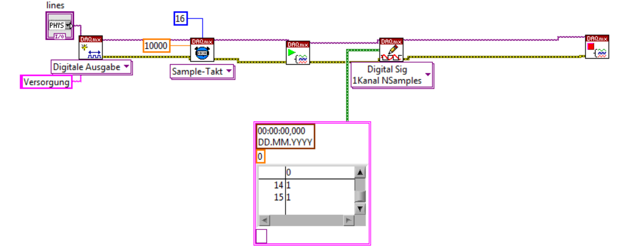
If you send 384 bits sequentially in a digital line; and running a timed software application, this would be possible (NI USB-6501 is a programmed software). See the example VI included below. In addition, please note that avoiding the nondeterministic East and will depend on the speed of your system. If you want to continue your application with one of our DIO cards that provide hardware timing capabilities; Please see the link below for more information about these devices.
Best regards
M Ali
Technical sales engineer
National Instruments
Tags: NI Hardware
Similar Questions
-
USB-6008 to give the digital output
Hi all
I was wondering anyone at - it base an example of an exercise using USB 6008 to give a digital output of a VI in Labview.
I am very new to the use of the USB 6008 AND Assistant DAQ and so far I've had reading a temperature, next step is I want the USB-6008 to give a + 5v output when the temperature reaches a certain value, I built a Labview 2009 VI for the temperature reading, but now I'm stuck on this piece.
Any help is appreciated! or if there are examples of laboratory exercises that exist that I can perhaps draw.
Hi Marko
Please take a look at the link that has some interesting and intuitive video to use the USB-6008 housing and how to set up the device for several applications in LabVIEW below. Please take a look at the step by step videos and let me know how you go. They are under the tab '"virtual Demos.
-
USB 6008 digital output signal
I am VERY new to LabView and have been racking my brain trying to get digital output of my USB-6008. All I want is to be able to get a signal of + 5 V of my digital output when I click on a button. This signal opens a valve on a system I see so when it is pressed, it must stay open until I press the new button. It seems simple enough to me, but I'm not too familiar with LabView. Help, please!
Stripling07
You must first take the LabVIEW tutorials and then look at the links to get started with DAQmx .
The simplest program would be with the DAQ Assistant. Drop it on your schema, and then select digital output > digital line. Select the line when the wizard has completed, click OK. Wire a Boolean value in a table to build and the output of which is connected to the data entry. That's all. You can test the output of MAX (Measurement & Automation Explorer) with the test Panel. Do NOT test with your connected tap. Your valve may require more current that can provide the 6008.

-
How can I improve my 2 digital output signals calendar?
Hello
I use a NI DAQ Pad-6015 (usb) with Labview 8.5 and XP to generate 2 digital outputs (high for the first 500ms and 600ms high for the second). The moment didn't need to be very specific, so I use not the 2 outputs hardware clocks. When runing of VI, and measure the length of the outputs with an oscilloscope, I get s 520ms and 640ms. This isn't a problem, but I still want to know, if I'm doing the right thing in my program, or if it is possible to improve it?
Thanks for your help,
Kind regards
Marc
Hello
Using all your advice I have exact measure now: only 0 to 4ms delay for signals from ms 500 and 600 using the NI DAQPad-6015.
PS: Timmer was right regarding the notice of usb. With my previous program when you use a card PCI of 6229, I had only a difference of 10 ms instead of 20 ms with the usb one.
Thanks for your help,
Kind regards
Marc
-
USB-6289 digital output signals setting
I use a USB-6289. I am writing a CVI application that uses this device. I need to put the digital i/o pins as outputs. In the CVI app, I know I can create these tasks with the tools-> create/edit DAQmx tasks. He created this:
Int32 CreateDAQTaskInProject(TaskHandle *taskOut1)
{
Int32 DAQmxError = DAQmxSuccess;
TaskHandle taskOut;DAQmxErrChk (DAQmxCreateTask ("DAQTaskInProject", & taskOut));
DAQmxErrChk (DAQmxCreateDOChan (taskOut, "USB-6289/port0", "))
"DigitalOut", DAQmx_Val_ChanForAllLines));
DAQmxErrChk (DAQmxSetChanAttribute (taskOut, "DigitalOut", DAQmx_DO_InvertLines, 0));* taskOut1 = taskOut;
Error:
Return DAQmxError;
}So this it puts in place but not to write the data. My question is what is the command to write the data?
Also I was wondering if the code source of any example that shows how these commands are made? Is it possible to configure the bits individually? I only need to use 5 of these pins as outputs so t would be coll if I could write that the bits D0 - D4.
Are there documents written on these commands and how they are used?
Thanks in advance
A DAQmxWrite writes the data.
Go to help > examples > material input and output > DAQmx > digital generation.
If you specify the lines instead of a port, you can use as the number of bits you want.
First glance using the ICB.
-
Data acquisition (different digital output at each iteration)
Hello
I am writing a LabView program using the NI USB 6501 24 e/s digital line.
I want DAQ to give ON / OFF according to the input data.
I call my DAQ more than once in a program so JUST
DAQ Assistant should work in iteration 0
2 DAQ assistant should work to the iteration 1
3 DAQ assistant should work to the iteration 2
I have attached my VI, please take a look.
Thank you
Rana
Because you do not order the same material, you must have DAQ Assistant 1. With your simple example, you could just build your 3 berries in a 2D array and the autoindex on the table on the loop FOR.
-
What is a digital output (DO) good for?
Actually, I wanted to use the outputs digital to move from a 24 VDC circuit (to turn on/off other devices etc.).
But the current output outputs digital is so low that I have even impossible to pass an opto-coupler (opto isolator).
That's why I wonder you use outputs digital for if you cannot use them to change anything?
Of course, I can create a circuit MOSFETS or transistors to switch 24VDC power with the TTL 5V digital output signal. But I guess that most of you do not :-)
And of course, I know that I can buy OR relay modules/cards. In fact, I have many digital outputs available and do not want to buy new modules/cards.
Now, I can test and actually I get 10mA @ 5V on a digital output of NI 9401 (DIO), using the digital output to pass an opto-Coupler.
It seems that the information contained in the data sheet are supposed to mean something else...
-
digital output without DAQ Assistant
Hello
I can produce a digital output signal of some sampling rate 10 kHz with the acquisition of data-assist. Now I would like to implement the same functionality with normal DAQ - screw, as I have to synchronize serveral exits lateron. However, I failed get the normal screws so that they work as the DAQ assistant. The most important thing is out the arbitrary signal with 10 kHz.
Thank you.
Thank you very much. The idea of watching inside the acquisition of data-assist helped.
-
NI USB-6501 digital output problem
Hello
I use DASYLab v.11 and I'm working on an interface with the NI USB-6501 where I'm putting a digital high on four ports.
With the module "NOR-DAQmx - digital input", I managed to read the digital inputs of the ' NI USB-6501 ".»
It's only the "NOR-DAQmx - digital output" I can't go to work.
Using 'NI MAX' of NOR I have easily can emmit my four LEDs in the way of my High/Low ports.
But not with DASYLab. When you use DASYLab tension on the ports remains unchanged.
Now, I have a switch module, generating 5/0, directly connected to the digital output module, which is assigned to my four output ports for my task.
I also tried with a module of relay between the two without success. I also tried to use 1.5 above instead of 5 without success.
I use the option 'Bus (0/5 supply) for the module "Digital output".
"NI Max", I configured the ports as "active drive.
Any suggestion of what I might be missing?
Thank you
Martin
Hmm, four ports, or four lines?
A port consists of eight lines. Each line can control an LED (ON / OFF ~ 0/5V).
If you have created a task to dig-out to control a port, 5V to this port sending sets all lines of this port to 'high '.
You need to 255 for each line one too high port (at the bit level: 128 + 64 + 32 + 16 + 8 + 4 + 2 + 1).<- eight="">
Or, you can create a dig out tasks to control four lines of a specific port.
Four lanes of the EEG DAQmx DigOut module.
Each of the channels of the modul will feed a single line of the task/device.
Four switches will then turn the lights, or turn off.
Make sure, that the 'bitposition' is the number of correct line (see picture).
-
Type of output USB 6501 digital IO
Hi, I'm new to this software.
I use an e/s digital NI USB-6501 24 lines.
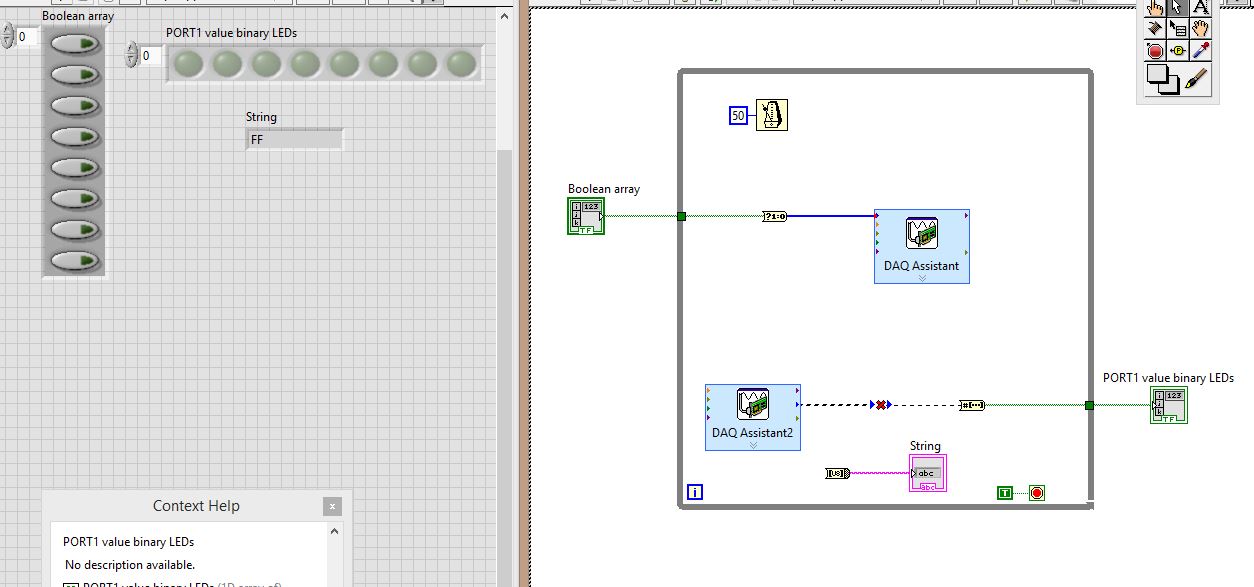
I physically wired PIN0.7:0 to PIN1.7:0, then all PORT0 go to PORT1
Click these buttons to table of Boolean, to set the output levels of PORT0, then having the signal wires to PORT1, which is then set accordingly, and then I want to ouput PORT1 using DAQ Assistant2 in:
(1) an array of Boolean LED
(2) a string indicating the value of the port in hexadecimal.
THE PROBLEM:
The DAQ Assistant2 outgoing data type is "table 1 d to unsigned long. The entry of the table that should receive it is "1-d array of boolean.
So, there is a data type mismatch.
How can I make this work? As you can see, I tried to place converters, I tried several converters, but I don't know what to do. Advice?
Stupid DAQ Assistant. I have no idea what is thinking want to a table. Personally, I just use the real DAQmx API. At least then you can say what is happening and it has less overhead.
A couple of other things:
You must move your controls and indicators for the acquisition of data inside the loop values. In this way they can be updated at each iteration of the loop.
Really, you must add a stop button. You need a way to cleanly stop your VI and do not use the button abandon in the toolbar.

-
How to generate a continuous ttl signal with a USB-6501
Hello everyone,
I am a beginner with LabView, so maybe my problem, it's very easy to fix.
I need to generate a digital output using a USB-6501. This TTL signal will then switch to a device. Basically, I need the digital output to be permanently to TTL high level until a user active departure is given. Then the digital output must stay to the TTL low level until another stop active user is given.
Does anyone have any suggestions on how to do? I have failed so far to get something different high TTL to my USB 6501.
Thank you very much.
Hi there, take a look at the VI I enclose. You can find more information about the device in textbooks and on this forum. I hope this helps
-
USB-6009 slow output signals using SignalExpress - error 200077
We have a Council of USB-6009 and Signal Express version 3.5.0
We want to generate low-frequency, analog and digital outputs to simulate some slow movement process.
We have created the signals and their generated as output, put when we RUN the project, we get error 200077, which seems to indicate that we must use On Demand distribution of signals.
If we choose On Demand, then the generate DAQmx says we have a missing entry.
So, what method should be used with the slow USB-6009 to generate box (.01Hz and slower) analog and digital outputs?
These are 2 of the projects, we tried - using On Demand, N samples, continuous, internal, and external triggering etc..
Thanks adavance for your help...
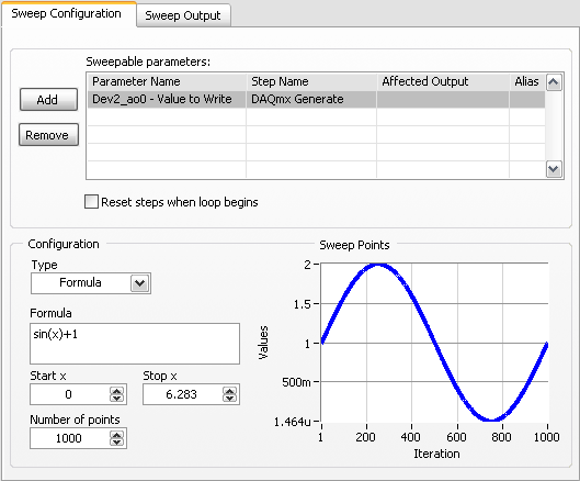
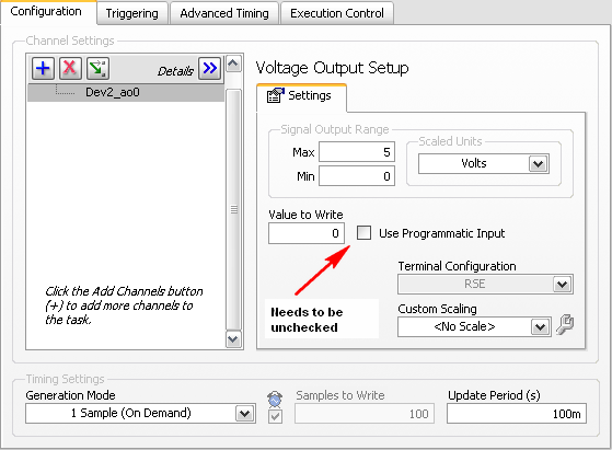
Welcome to the forums of Steve,
I have good news for you. I played a bit with the sweep and actually got a code facing up to generate a slow signal. I went and tested it with the 6009 and he was able to run without any errors. I joined here, but if you have to open (or anyone else in the future), here are some screenshots of how it works. If this works, feel free to make the forum as resolved while others can locate a solution a little easier in the future.
Scan Configuration:
DAQmx Config:
-
Is it save to use the digital output as a digital input for another channel signal
Hi all
I know it's a stupid question, but I don't have another generator of signals by hand. What I want to know is, can I use the signal digital output of my USB-6001 as an input for the same signal device, but on other digital port? I wasn't directly because I don't want to burn the device...
Thank you
Done all the time. No problems.
-
take the digital output USB-6001 always high or low in c
Hi all
I am new to the NI DAQ interface. I have a USB-6001 and I am trying to use this device to control some flowchart in C. What I want to do is:
* set digital output lines with high and low intensity and change their status as needed (in C).
I tested the device NEITHER Max--> Test panels and found that the device is capable to do that. Then I try to do in C. I have checked hace examples and function I use is one called "DAQmxWriteDigitalU32". I have problem in the understanding of its input parameters. I tried something with my own knowledge, but it does not work as I expected. Here is a test I did:
data uInt32 = 1;
Int32 wrote;
TaskHandle taskHandle = 0;
DAQmxErrChk (DAQmxCreateTask("",&taskHandle));
DAQmxErrChk (DAQmxCreateDOChan (taskHandle, "Dev1/port0/line7", "", DAQmx_Val_ChanForAllLines));
DAQmxErrChk (DAQmxStartTask (taskHandle));
DAQmxErrChk (DAQmxWriteDigitalU32(taskHandle,1,1,10.0,DAQmx_Val_GroupByChannel,&data,&written,));taskHandle = 0;
DAQmxErrChk (DAQmxCreateTask("",&taskHandle));
DAQmxErrChk (DAQmxCreateDOChan (taskHandle, "Dev1/port0/$line0", "", DAQmx_Val_ChanForAllLines));
DAQmxErrChk (DAQmxStartTask (taskHandle));
DAQmxErrChk (DAQmxWriteDigitalU32(taskHandle,1,1,10.0,DAQmx_Val_GroupByChannel,&data,&written,));I just want to set ' Dev1/port0/line7' and ' Dev1/port0/$line0"at a high level, but only ' Dev1/port0/$line0' answer me. The second parameter of the DAQmxWriteDigitalU32 function is numSampsPerChan. If I replace (currently 1) with a higher value, such as 100, I see that "Dev1/port0/line7" sends a number of 1 output, then back to 0. So I guess that the problem is just that I understand not all parameters for the DAQmxWriteDigitalU32 function. Is someone can you please tell me how I can set up a line of digital output 1 or 0?
Thank you!
Hongkun
Hello
I finally find a way to do it! The feature works very well, and my problem was not set the data value to write correctly. It seems that if I want to write a 1 to the port0/line1, I put "data = 2 ^ 1" rather than "data = 1", because by default it is the second bit of the port.» Similarly, "data = 2 ^ 7 ' high level to port0/line7. I find that this setting is surprising when you want to control an individual line. It seems more reasonable when you control the whole port. In any case, is to solve the problem!
Thanks anyway!
Hongkun
-
Timed signal generation TTL with the NI USB-6501 to be read by Arduino Uno
First of all, I want to apologize - I am very, very new to LabVIEW and brand new to the development of the software of control equipment in general. I tried to find an answer to this question already, but I'm not entirely sure what I'm looking for.
I have currently a work program LabVIEW which operates a gun card NI USB-6501. Due to the nature of having a machine that springs from a powerful beam of electrons, we want to assure you that if the computer controlling stalls or fails for any reason, we have built-in security that can stop the gun. Our current idea is to connect an Arduino Uno on a PIN on the USB-6501 and LabVIEW to generate a timed signal, which may read the Arduino. If the signal fails (indicating that the control computer has queued or off), the Arduino triggers a power relay that is independent of the control computer and turns off the gun.
I understand that the USB-6501 operates on TTL signals, so the signal that I should be something in the sense of "output TTL high, wait 1 second, output low expectations, a second, repeat TTL ', but I have no idea how to go about programming in LabVIEW. My first thought was that it is a square wave by using the function "simulate the signal" output, or to have trigger an iterative Boolean signal, by using the function 'DAQmx write', but I don't really understand how do to implement or another idea, or if an idea would even work.
Any advice would be greatly appreciated.
Hi Elizabeth,.
THINK THE STREAM!
When do you DATAFLOW think everything falls in places!

Several problems:
-You have to put that MAKE impulse VI in his own loop parallel to your main VI!
-When you place this generation of impulses in the effects loop ("TTL arduino low-high") you should put the CreateTask and StopTask outside the loop: no need to create/stop the task in each iteration.
-Why are there points of constraint to waiting functions?
-Why is there bent wires? You know Ctrl-U?
-LabVIEW comes with an extensive library of example screws: you looked at all these examples DAQmx?
-Suggestion: Learn more about the "structures of producer-consumer"!

Maybe you are looking for
-
Re: Satellite A200 Touchpad work scroll dosnt after installing Win 7
When I change my windows XP to 7 w my scroll dosen t work.What should I do? Sorry for my English...
-
Control (Ctrl) and function (Fn) keys are exchanged on the ProBook s 4530. How can I restore it?
I have the HP ProBook s 4530, who worked as expected i.e. keys Ctrl and Fn keys work properly. Now somehow these two keys are reversed and I want to restore as well as Ctrl Key functions as Ctrl key. Please note that I am running Windows 7 on this co
-
DVD Drive Power Off and does not restart
DVD Multi hunt in my ThinkPad W530 assignments after a while to save battery. But when I go into my computer, make a straight on the drive and click to turn on, nothing happens. The Player opens and allows me to put the disc in it, but no program on
-
I see that the G7-2323DX has no drivers for the operating systems Windows 7 family. Made the downgrade to Windows 7, however, I now need a list of the material (e.g., motherboard, chipset, PCI, USB, etc.) and/or list of required drivers to complete
-
Cannot connect in the company of the iDrac 6
iDRAC Enterprise never works on the login page that is a known issue on the net. I can not connect via Firefox, IE11, Edge, nothing. It refreshes the page in IE11 or connection, connect and everything says "undefined". Yet, it works in mobile Safari.