USB-6501 is and Off is on
Hello
I have a USB-6501.
When I send the value True to the writing DAQmx digital VI the signal from the equipment turns off, and when I wire a false material passes.
The same thing happens with an entry. Causes a short circuit between the terminals and ground out the fake DAQmx for read, and unconnected with this is true.
A colleague has the same problem with the 6501, but not with its PCI DAQ card.
It is somewhat paradoxical when programming. Is there a way to reverse this behavior? (other than just not forgetting to add in one does not)
Simple test VI attached.
Phil_ wrote:
Tested with a different usb-6501 on another machine. Same problem...
If your work Apok ok, so it's really weird.
Would you care to elaborate on the above Apok?
My knowledge of electronics is minimal
your IO is linked to a 4.7Kohm resistance which is also connected to 5Vdc. transistor is turned off, output pulls up to the level of 5Vdc and... output transistor pulls up close gnd, given a drop of transmitter led
Tags: NI Hardware
Similar Questions
-
USB-6501 - impossible to find a basic example of Labview
Hello
I recently bought a USB-6501 card and I used it in my own succesfully end and C++ programs using the DAQmx drivers.
Then I tried to move to Labview 2009 (I never used Labview) so I looked for a simple example.
I tried to boot from the example 'interactive Control Panel' (http://digital.ni.com/public.nsf/allkb/AF0F31EE5D2AD23F862573140009D7C2?OpenDocument).
I had to install the 'DAQmx Base' for him to start, as described in the previous link. now it begins (before Labview attempted to get a few missing .vi) but I get a message "error 200220 occurred at an unidentified locatio.
Then I realized this example is 'old' (as explained here: http://forums.ni.com/ni/board/message?board.id=170&thread.id=209247), and it is suggested to look for a new one in example Finder ' entry-level equipment / output-> DAQmx-> Digital measurement (or generation)-> read Dig Port.VI.
I tried, but along the way ' entry-level equipment / output-> DAQmx-> "only a folder named"Analog Measurement\Voltage"exists.
Also in the search for 'Reading dig Port.VI' does not work.
I've already spent many hours in this research and tent and the fact that I am not able to find not even a basic example, it is quite frustrating and it is making me give up the idea of using Labview.
Please can anyone give me any suggestions where find/download an example simple and minimum to use my USB6501 in Labview 2009?
Thank you
Scipione.
First, install DAQmx Base was a mistake. Uninstall it and then install the Driver-OR-DAQmx. The driver must be installed after the installation of LabVIEW. After installation, make sure that the device is listed in MAX under "DAQmx devices. If it is not, your installation is still not correct.
To search for example LabVIEW, see help > find examples. Under Input and Output hardware > DAQmx, you will find the digital generation and numerical measures. You have to look at the simple, timed software examples such as read write dig Chan, writing Port to dig, dig chan, reading Dig Port. You also have the option to use the DAQ Assistant.
-
USB-6501 as Stepper Motor Driver
Hello
I've been away from LabVIEW for awhile (6 years or more) and I have a small task to achieve and am really struggling to start.
I have a USB-6501 DIO and Labview version 8.6. I need to drive a motor not not that requires 4 input (in my case 2 Port (0 to 3)) and depending on the phase of these 4 signals with respect to the other (its a circuit of H-bridge) the engine to drive forward or backward.
I started with DAQ assistant and I seem to be communicating correctly with the OID and the engine, but I'm not at the stage of being able to produce my 4 signals. I know that the USB-6501 must be controlled with a timing (as opposed to the generation of a train of function for example). However I am stuck at start-up my possible solutions seem very long breath that I was wondering if there was a quick and easy solution to produce my 4 signals? I don't know I'm missing something.
Any help/comments would be greatly appreciated, as I'm very rusty and I have no time my solution.
See you soon,.
Karen
I solved my problem...

-
How do I turn on/off outputs multiples with a single button using USB-6501 & Labview 2010
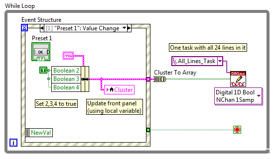
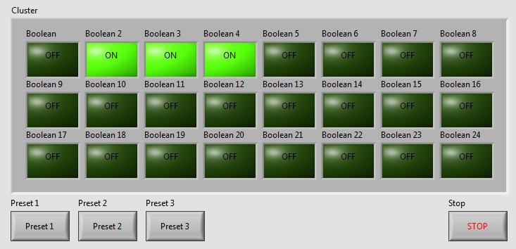
I've written a VI with 24 buttons, one for each output of the USB-6501, for turning on and off 24 relay. Now, I want to add more buttons that activate and deactivate the outputs multiple. We will call these Presets buttons and pressing the Preset button a few outings turn and some turn off. Get it? The VI I've included a screen shot is used to test a transmission controller and rather than to manually select one at a time relay I want a preset button that sets up instantly relays for the next stage of the event.
The VI I wrote uses tasks created in NI MAX.
I am a beginner of Labview, so please try to keep your easy to understand solutions if possible.
Thank you
Kevin
BTW, I'm registered in Core 1 and 2 month next to Richardson, Texas.
Here's an example - you will learn about the grapes, berries, events, etc., in the class, but this will give you a head start. Code is attached but I took a screenshot to give people an idea of how simple the schema becomes:
As your learn about them, I suggest you also make the cluster a TypeDef and make management mistakes, but I've omitted the example to keep things as simple as I could.
Good luck, LabVIEW learning, it is worth!
~ Simon
-
USB-6008, USB-6501 and Embarcadero C++
Hello NEITHER and NOR users,.
I spent a considerable amount of money several years ago on a number of devices USB-6008 and USB-6501 for a class that I teach on interfacing the simulations with realworld sensors and actuators. Write us code using Embarcadero C ++ Builder and we wrote the code to interface with the jury of EZIO AD / DA via RS - 232. The EZIO is much too slow and limited. Given advertising NOR, we bought these boards, but after several attempts to get some information OR on the way to talk to these devices directly via C++, we have yet no valid response. No, I don't want to LabView or any additional expenses. I just want to talk to them directly.
OR: are you ready to help with this, or not? If this is not the case, although wanting to refund these purchases. Announce as being accessible from C++, but you are not willing to provide any help of substance to this day...
Yes, I am self-taught, write code, and old-school enough to feel that I have a right to know how to talk to all the devices I buy. I confess my ignorance, but I'm sick and tired of secret corporate and misleading advertising.
Can someone please provide me with enough example of code to start. That's what we wrote for the EZIO:
http://www.Duke.edu/Web/ISIS/Gessler/Borland/RealWorld-Ezio.htm
We would like to start writing similar code for these materials of NEITHER. If possible, we can buy more. If this is not the case, these cards are useless.
Kind regards
Nick
Nicholas Gessler, PhD.
Nick,
When you have installed the DAQmx drivers to communicate with the 6008 and 6501, I assume you also installed programming examples? It is here that they are on my XP machine: C:\Documents and Settings\All Users\Documents\National Instruments\NI-DAQ\Examples\DAQmx ANSI C. I don't think that Embarcadero C++ Builder is one of the languages supported, so you'll need to twist your compiler, but it should give you a good start.
Tom
-
USB-6501 and opto-coupler SFH615A
Hello
I'm driving an opto-coupler (Siemens SFH615A - spec link attached) using the USB-6501. I am really a beginner and I am looking
help on how I can connect it. I have tried a few options already but no luck.
http://docs-Europe.Electrocomponents.com/WebDocs/009C/0900766b8009c194.PDF
I use a Servo-Drive in a project, a motor drive. Unfortuantely USB-6501 turns out logically lines high on the servo-controller startup is
receipt of a signal. I hope I can pass the INHIBITION of the servo drive line, through the opto-Coupler, so when you start 6501 will cause the optocoupler
circuit close to inauguration of the line inhibit preventing displacement engine. The labview program will make the logic of the bass line to allow the engine to move.
Looking at the manual of the USB-6501 and previous questions, there are 2 ways to do this, but working on resistance, values etc. required is
still a bit beyond me, and unfortunately I'm a bit stuck for the moment.
Any help would be greatly appreciated, thank you.
OK got it works, I hope it will be useful for others.
My problem, I think, have no idea really, is the impedance of the I/O device. Despite everything, I used a buffer of gain of the unit with the help of the
Intersil ICL7611 powered by the + 5V line with the line of digital output connected the + IN the axis of the ICL7611. On the output, I have a
Resistance 120 ohm before the opto SFH615A. Opto is open beginning 6501 and high but closed low logic logic. Happy days until the
the next problem happens
-
How to get 5V off NI USB 6501 from + 5 v source
Hi all
I have a problem that when I plug the usb adapter into my desktop usb and measure the source pin 5V, I get the output from this PIN voltage I NI USB 6501 DAQ board. its 0v
Y at - it all the necessary parameters to allow the + 5V voltage source.
How can I activate the source of 5V to NI USB 6501
Please let me know
You don't have to do anything to turn it on. What two pins connect you to when you take the step?
-
Conduct and variation LED with USB-6501
I have a bunch of LEDs connected to a power supply with an intermediate dimmer. The specifications for all this material is listed below. I'm looking to move from manual control to digital I/o. I have an NI USB-6501 data acquisition, but have never worked with her before and so would like some tips. The goal is to maintain a maximum brightness, but be able to fade the lights of my software. I read several threads on simple power control but that you did not find anything on the gradation.
John.
Lights: (red)
Drive:
Power source: (15 Watts)
http://www.superbrightleds.com/moreinfo/power-supplies/12VDC-CPS-series-power-supply/68/
In order to control something, you must be able to physically connect the 6501, but it does not appear that have anything to connect to. The image of the drive, it has just one button.
-
Difference between USB power on and power off in W510
Hi there everyone!
I have not found a lot of information on this topic... Maybe a stupid question, but I need help...

I was thinking of W510 purchase. Then, East-USB3 ports powered? I ask, because in the sales ads that I was looking for, they inform about two USB 3.0, a powered USB 2.0 and a USB 2.0/eSATA combo port. Then I started to worry, is powered by the 3.0 port. This is rather important, because I need the port superspeed for video capture, and my capture (Blackmagic intensity shuttle) draws its energy device is USB.
Thank you in advance for support!
Hello mate,
All usb ports feed. What they mean by powered is that the usb 2.0 port is always powered even when the computer is turned off. This port is in the back and yellow. The other ports are not powered when the laptop is turned off, but they are when it is turned on.
-
USB-6008 turning outputs ON and OFF
I'm new to LabVIEW. This is the first time I tried to write a VI that communicates with an external device. Everything I'm doing adjust tensions and put on or off the two analog outputs for a USB-6008. I don't read all the entries or do something with the outputs digital, I want to just turn out analog ON and OFF.
Here's what I have so far.
It does the job of setting that puts the analog output to the USB-6008.
The only thing left to do is to make an executable file. I don't have any idea on how to do it again.
I'm sure a true guru LabVIEWw could have done better, but it does the job.
-
On and off a WiFi with USB adapter
I bought a new computer. My current computer has Gigaset router for wireless connections. I am able to easily connect with my laptop. I bought a N150 Wireless USB adpater to my new computer so it can connect to the internet via my home WiFi. It connects but he kick a few seconds, then it reconnects, then starts again. It is on and off. Meanwhile, I have constantly able to connect with my other computer (plus one). Is there enough wi - fi seamless adapter? I don't know what to do. Please notify.
Hello
Welcome to the Microsoft community where you can find all the answers related to windows.
According to the description, it looks like you are facing a problem with the wireless network, he would be grateful if you can answer this question in order to help you further.
1. have you made changes on the computer before this problem?
2. you receive an error message or error code?
I suggest you to see the steps in the following Microsoft article and check if it helps.
Wireless and wired network problems: http://windows.microsoft.com/is-IS/windows/network-connection-problem-help#network-problems=windows-xp&v1h=win8tab1&v2h=win7tab1&v3h=winvistatab1&v4h=winxptab1
How to troubleshoot wireless network connections in Windows XP Service Pack 2: http://support.microsoft.com/kb/870702
If you have any other questions or you need Windows guru, do not hesitate to post your questions and we will be happy to help you.
-
NI USB-6501 digital output problem
Hello
I use DASYLab v.11 and I'm working on an interface with the NI USB-6501 where I'm putting a digital high on four ports.
With the module "NOR-DAQmx - digital input", I managed to read the digital inputs of the ' NI USB-6501 ".»
It's only the "NOR-DAQmx - digital output" I can't go to work.
Using 'NI MAX' of NOR I have easily can emmit my four LEDs in the way of my High/Low ports.
But not with DASYLab. When you use DASYLab tension on the ports remains unchanged.
Now, I have a switch module, generating 5/0, directly connected to the digital output module, which is assigned to my four output ports for my task.
I also tried with a module of relay between the two without success. I also tried to use 1.5 above instead of 5 without success.
I use the option 'Bus (0/5 supply) for the module "Digital output".
"NI Max", I configured the ports as "active drive.
Any suggestion of what I might be missing?
Thank you
Martin
Hmm, four ports, or four lines?
A port consists of eight lines. Each line can control an LED (ON / OFF ~ 0/5V).
If you have created a task to dig-out to control a port, 5V to this port sending sets all lines of this port to 'high '.
You need to 255 for each line one too high port (at the bit level: 128 + 64 + 32 + 16 + 8 + 4 + 2 + 1).<- eight="">
Or, you can create a dig out tasks to control four lines of a specific port.
Four lanes of the EEG DAQmx DigOut module.
Each of the channels of the modul will feed a single line of the task/device.
Four switches will then turn the lights, or turn off.
Make sure, that the 'bitposition' is the number of correct line (see picture).
-
Generation of voltage USB-6501
Hi all
I am very new to the use of devices to LabView and NI, so forgive me if my question seems stupid.
I have an acquisition of data NI USB-6501 I want to use to connect to a device that will open or close a lid when triggered.
My question is: is it possible to programmatically trigger the nominal voltage of the USB-6501?
I'm using LabView for this and I am running on Windows 7. I couldn't find examples of LabView bases that were related to the output voltage for the USB-6501.
Any help would be really appreciated, thanks in advance
Thanks for your replies.
After a few changes, the example "Write dig Chan" helped me to get the behavior I want to put on and a device plugged power off.
-
Timed signal generation TTL with the NI USB-6501 to be read by Arduino Uno
First of all, I want to apologize - I am very, very new to LabVIEW and brand new to the development of the software of control equipment in general. I tried to find an answer to this question already, but I'm not entirely sure what I'm looking for.
I have currently a work program LabVIEW which operates a gun card NI USB-6501. Due to the nature of having a machine that springs from a powerful beam of electrons, we want to assure you that if the computer controlling stalls or fails for any reason, we have built-in security that can stop the gun. Our current idea is to connect an Arduino Uno on a PIN on the USB-6501 and LabVIEW to generate a timed signal, which may read the Arduino. If the signal fails (indicating that the control computer has queued or off), the Arduino triggers a power relay that is independent of the control computer and turns off the gun.
I understand that the USB-6501 operates on TTL signals, so the signal that I should be something in the sense of "output TTL high, wait 1 second, output low expectations, a second, repeat TTL ', but I have no idea how to go about programming in LabVIEW. My first thought was that it is a square wave by using the function "simulate the signal" output, or to have trigger an iterative Boolean signal, by using the function 'DAQmx write', but I don't really understand how do to implement or another idea, or if an idea would even work.
Any advice would be greatly appreciated.
Hi Elizabeth,.
THINK THE STREAM!
When do you DATAFLOW think everything falls in places!

Several problems:
-You have to put that MAKE impulse VI in his own loop parallel to your main VI!
-When you place this generation of impulses in the effects loop ("TTL arduino low-high") you should put the CreateTask and StopTask outside the loop: no need to create/stop the task in each iteration.
-Why are there points of constraint to waiting functions?
-Why is there bent wires? You know Ctrl-U?
-LabVIEW comes with an extensive library of example screws: you looked at all these examples DAQmx?
-Suggestion: Learn more about the "structures of producer-consumer"!
-
Satellite L20: Can I disconnect devices such as USB mouse without turning off the power?
Hi all.
I am owner of laptop Satellite L20. I always turned off power to my computer when I need to connect or disconnect a USB device. Some devices have a special icon on the toolbar disconnect them, but some don't (FDD USB or flash drives). Can I disconnect and connect devices such as mouse USB or Scanner wihtout turning off the power?Hello
You can disconnect the external USB devices without turning off the unit, but you must use the option "remove hardware" before you cut the material.
The icon "Remove hardware" usually appears with resources such as hard drives or USB key have the ability to buffer data. It of necessary for this buffer to the device before emptying it is disconnected
Maybe you are looking for
-
How to uninstall El Capitan and replaces it with clone of Snow Leopard?
I had a chance terrible execution El Capitan, including in connection with CS5. It takes (literally) 10 x more time to save a .tiff file in El Capitan, than that of Snow Leopard. I suspect much too many processes running in the background, which most
-
Reference Dell does a Sync G monitor?
As a G-sync 1440 to go with my GTX 970 p monitor?
-
How can I configure Messenger to record my conversations, record them and send them to a location I can read and save when you use Messenger on other computers than mine? original title: Live Messenger
-
I needed to update my credit card on my account and I thought he was under another email address, in which I also have an Adobe account. Creative cloud, which I use now is linked to an account that I am using, but I've added a credit card and renewed
-
Do I really need a server license 5.0 vcenter for my vsphere Enterprise 5.0
Hi all, im new to the Forum vmware and encryption currently in terms of licensing for our small internal data center facility.My physical features are for licensingGuests: 2Number of CPUS: 4by CPU core: 6For each host RAM: 32 GB will later expand to