USB-6501 open collector signal generation
Hi all
I have carefully read the manual for this product, and I think that's what I'm looking for, but I was hoping just to get confirmation from someone who knows a bit more about it as I do. I have a stepper motor command that accepts control impulses. The differential voltage between the 2 input pins must be between 2.5 and 5 V DC. The control pulses can be RS422 or open collector type signals. The maximum heart rate is 250 kHz, pulse length must be greater than or equal to 2 microseconds and the time between two pulses must not be greater than 40 milliseconds. The engine must operate continuously for an extended period of time. Yet once, seeking confirmation that DIO can produce the signal I need. Thanks for any help.
It seems to me that this module can be adapted to be connected to your driver module. Output configuration you need is called "open-drain output" in the data sheet.
It is possible to drive a stepper motor driver with a generalist module e/s. But (in most cases), it is NOT possible to drive of a driver of motor Stepper with a constant pulse. You will need a rate of acceleration, i.e. it must increase the frequency of the pulses of zero to the desired speed of the engine.
Tags: NI Hardware
Similar Questions
-
Timed signal generation TTL with the NI USB-6501 to be read by Arduino Uno
First of all, I want to apologize - I am very, very new to LabVIEW and brand new to the development of the software of control equipment in general. I tried to find an answer to this question already, but I'm not entirely sure what I'm looking for.
I have currently a work program LabVIEW which operates a gun card NI USB-6501. Due to the nature of having a machine that springs from a powerful beam of electrons, we want to assure you that if the computer controlling stalls or fails for any reason, we have built-in security that can stop the gun. Our current idea is to connect an Arduino Uno on a PIN on the USB-6501 and LabVIEW to generate a timed signal, which may read the Arduino. If the signal fails (indicating that the control computer has queued or off), the Arduino triggers a power relay that is independent of the control computer and turns off the gun.
I understand that the USB-6501 operates on TTL signals, so the signal that I should be something in the sense of "output TTL high, wait 1 second, output low expectations, a second, repeat TTL ', but I have no idea how to go about programming in LabVIEW. My first thought was that it is a square wave by using the function "simulate the signal" output, or to have trigger an iterative Boolean signal, by using the function 'DAQmx write', but I don't really understand how do to implement or another idea, or if an idea would even work.
Any advice would be greatly appreciated.
Hi Elizabeth,.
THINK THE STREAM!
When do you DATAFLOW think everything falls in places!

Several problems:
-You have to put that MAKE impulse VI in his own loop parallel to your main VI!
-When you place this generation of impulses in the effects loop ("TTL arduino low-high") you should put the CreateTask and StopTask outside the loop: no need to create/stop the task in each iteration.
-Why are there points of constraint to waiting functions?
-Why is there bent wires? You know Ctrl-U?
-LabVIEW comes with an extensive library of example screws: you looked at all these examples DAQmx?
-Suggestion: Learn more about the "structures of producer-consumer"!
-
Generation of voltage USB-6501
Hi all
I am very new to the use of devices to LabView and NI, so forgive me if my question seems stupid.
I have an acquisition of data NI USB-6501 I want to use to connect to a device that will open or close a lid when triggered.
My question is: is it possible to programmatically trigger the nominal voltage of the USB-6501?
I'm using LabView for this and I am running on Windows 7. I couldn't find examples of LabView bases that were related to the output voltage for the USB-6501.
Any help would be really appreciated, thanks in advance
Thanks for your replies.
After a few changes, the example "Write dig Chan" helped me to get the behavior I want to put on and a device plugged power off.
-
How to generate a continuous ttl signal with a USB-6501
Hello everyone,
I am a beginner with LabView, so maybe my problem, it's very easy to fix.
I need to generate a digital output using a USB-6501. This TTL signal will then switch to a device. Basically, I need the digital output to be permanently to TTL high level until a user active departure is given. Then the digital output must stay to the TTL low level until another stop active user is given.
Does anyone have any suggestions on how to do? I have failed so far to get something different high TTL to my USB 6501.
Thank you very much.
Hi there, take a look at the VI I enclose. You can find more information about the device in textbooks and on this forum. I hope this helps
-
USB-6501 384 bit synchronized digital output signals
I need three digital signals (please see the attached file) to control a device, a signal is the clock signal, one is a continuous data signal 384 bit and another strobe signal that informs the device start and stop data. I have a USB-6501, this task can be achieved? I don't know how to write a 384-bit with DAQmx write signal, because it seems to support up to 32 bits. And it will be difficult to synchronize?
Thank you!
Hello the Stork
If you send 384 bits sequentially in a digital line; and running a timed software application, this would be possible (NI USB-6501 is a programmed software). See the example VI included below. In addition, please note that avoiding the nondeterministic East and will depend on the speed of your system. If you want to continue your application with one of our DIO cards that provide hardware timing capabilities; Please see the link below for more information about these devices.
Best regards
M Ali
Technical sales engineer
National Instruments
-
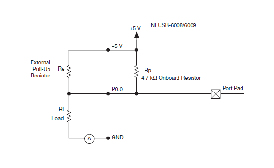
Pull-up external USB-6009. digital output (open collector) allows onboard external + 2.5 V output?
Pull-up external USB-6009. digital output (open collector) allows onboard external + 2.5 V output?
Hello
I want to config output digital USB-6009 to + 2.5 V above and 0 V digital output low. I know I can config USB-6009 digital output open collector with resistance to pull-up external, that can be applied with + 2.5 V power source.
My question is: can I use USB-6009 Board + 2.5 V output as the current source of resistance to pull-up? What resistance is a good number for the resistance to pull-up, if I can use this configuration?
Thank you much for the help.
Cathy
Hi Cathy,.
The digital USB 6008 front-end server looks like this:
So, there is actually an internal pullup to 5V 4.7 kOhm resistance when the device is configured to open collector.
If you want to display 0 to 2.5 V, I would look in a resistance of polarization of 4.7 kOhm between c and ground (according to the rest of your tour).
Best regards
-
Hi all
I have a brand new NI USB-6501, and I'm looking for more help with the operation. I'm running OS X 10.11.1, LabVIEW 2013 SP 1, NI-VISA 15.0 and NOR-DAQmx Base 15.0.0. I set up and plugged my module and get the flashing green light stable. I ran NI MAX, found the module and renamed 'Motor_Module '. Then, I went to my DAQmx Base of examples and found the Control.llb Interactive USB-6501 and ran the interactive VI control that is contained in this library.
The first thing I tried was simply running the VI. I got error-200220, device ID is not valid. I changed the name of the device to "Motor_Module" and run the VI. This time, I got error-200558, a task cannot contain multiple independent devices. Create a task for each independent device.
And here I am. My ultimate goal is to have this output module signal collector type open to + 5 V. Any help would be greatly appreciated. Thank you.
Hi Sullivnc,
I would recommend you look at a few examples in the Finder for example of OR. Under input and output hardware, there is a folder for DAQmx who has a record for a digital output which has some useful examples. If you do continuous or left over, you can add more stuff to your code as a clear task DAQmx, vi DAQmx Timing, and/or vi DAQmx task is made.
-
USB-6501 and opto-coupler SFH615A
Hello
I'm driving an opto-coupler (Siemens SFH615A - spec link attached) using the USB-6501. I am really a beginner and I am looking
help on how I can connect it. I have tried a few options already but no luck.
http://docs-Europe.Electrocomponents.com/WebDocs/009C/0900766b8009c194.PDF
I use a Servo-Drive in a project, a motor drive. Unfortuantely USB-6501 turns out logically lines high on the servo-controller startup is
receipt of a signal. I hope I can pass the INHIBITION of the servo drive line, through the opto-Coupler, so when you start 6501 will cause the optocoupler
circuit close to inauguration of the line inhibit preventing displacement engine. The labview program will make the logic of the bass line to allow the engine to move.
Looking at the manual of the USB-6501 and previous questions, there are 2 ways to do this, but working on resistance, values etc. required is
still a bit beyond me, and unfortunately I'm a bit stuck for the moment.
Any help would be greatly appreciated, thank you.
OK got it works, I hope it will be useful for others.
My problem, I think, have no idea really, is the impedance of the I/O device. Despite everything, I used a buffer of gain of the unit with the help of the
Intersil ICL7611 powered by the + 5V line with the line of digital output connected the + IN the axis of the ICL7611. On the output, I have a
Resistance 120 ohm before the opto SFH615A. Opto is open beginning 6501 and high but closed low logic logic. Happy days until the
the next problem happens

-
Best way to generate the software clock for USB-6501 of Measurement Studio for c# VS2008
Hi all
I wonder if there is a better way to generate a clock software for USB-6501 of Measurement Studio for VS2008 in C Sharp?
I have developed a clock using C Sharp "Thread.Sleep (msecPauseTime)"; and statements to switch digital output high and low. There are a few things I noticed in creating a software clock in this way:
- The smallest delay by the Thread.Sleep command time is 1 millisecond (which means higher clock period is 2 msec-500 Hz, not holding not ball account no. 2 below).
- Sometimes the delay I see on an oscilloscope is considerably longer than the delay that I specified in the sleep command.
In my application, I create signals (a clock, a latch enable and data series) to control what an attenuator step through the USB-6501 RF connected to a USB 2.0 on my computer. This particular step RF attenuator can accept clocks with frequencies up to 10 MHz, so I would like to generate a software clock (without having to connect to an external clock to a line of input on the USB-6501) which is closest to this maximum frequency, and I think that the USB2.0 line could handle clock speeds over 500 Hz. Also, I would like to know why the delays that I see on the scope are sometimes longer than the time specified by the Thread.Sleep command. Is it caused by the suspension of the execution of my program processor for something else, as I suspect? Of course, this isn't a big deal, because it does not affect the time as my serial data and pieces change compared to my clock. However, I would like to know why it does this.
I appreciate your help.
Thank you
Jonathan Becker
Doctoral research engineer
Carnegie Mellon Silicon Valley
Jonathan,
Since the USB-6501 DIO is software programmed, you are at the mercy of the planning of the operating system and won't be able to work reliably with an external clock in the software.
You can try to set the priority of your thread 'generation of clock' to improve performance, however, because Windows is not a deterministic operating system, there are still no guarantees. Operating systems are not required to honor the priority of threads. You can find examples and information on the definition of the priorities of the threads in c# here:
http://msdn.Microsoft.com/en-us/library/system.Threading.thread.priority.aspx
Kind regards
-
USB-6501 as Stepper Motor Driver
Hello
I've been away from LabVIEW for awhile (6 years or more) and I have a small task to achieve and am really struggling to start.
I have a USB-6501 DIO and Labview version 8.6. I need to drive a motor not not that requires 4 input (in my case 2 Port (0 to 3)) and depending on the phase of these 4 signals with respect to the other (its a circuit of H-bridge) the engine to drive forward or backward.
I started with DAQ assistant and I seem to be communicating correctly with the OID and the engine, but I'm not at the stage of being able to produce my 4 signals. I know that the USB-6501 must be controlled with a timing (as opposed to the generation of a train of function for example). However I am stuck at start-up my possible solutions seem very long breath that I was wondering if there was a quick and easy solution to produce my 4 signals? I don't know I'm missing something.
Any help/comments would be greatly appreciated, as I'm very rusty and I have no time my solution.
See you soon,.
Karen
I solved my problem...
-
USB-6501 - impossible to find a basic example of Labview
Hello
I recently bought a USB-6501 card and I used it in my own succesfully end and C++ programs using the DAQmx drivers.
Then I tried to move to Labview 2009 (I never used Labview) so I looked for a simple example.
I tried to boot from the example 'interactive Control Panel' (http://digital.ni.com/public.nsf/allkb/AF0F31EE5D2AD23F862573140009D7C2?OpenDocument).
I had to install the 'DAQmx Base' for him to start, as described in the previous link. now it begins (before Labview attempted to get a few missing .vi) but I get a message "error 200220 occurred at an unidentified locatio.
Then I realized this example is 'old' (as explained here: http://forums.ni.com/ni/board/message?board.id=170&thread.id=209247), and it is suggested to look for a new one in example Finder ' entry-level equipment / output-> DAQmx-> Digital measurement (or generation)-> read Dig Port.VI.
I tried, but along the way ' entry-level equipment / output-> DAQmx-> "only a folder named"Analog Measurement\Voltage"exists.
Also in the search for 'Reading dig Port.VI' does not work.
I've already spent many hours in this research and tent and the fact that I am not able to find not even a basic example, it is quite frustrating and it is making me give up the idea of using Labview.
Please can anyone give me any suggestions where find/download an example simple and minimum to use my USB6501 in Labview 2009?
Thank you
Scipione.
First, install DAQmx Base was a mistake. Uninstall it and then install the Driver-OR-DAQmx. The driver must be installed after the installation of LabVIEW. After installation, make sure that the device is listed in MAX under "DAQmx devices. If it is not, your installation is still not correct.
To search for example LabVIEW, see help > find examples. Under Input and Output hardware > DAQmx, you will find the digital generation and numerical measures. You have to look at the simple, timed software examples such as read write dig Chan, writing Port to dig, dig chan, reading Dig Port. You also have the option to use the DAQ Assistant.
-
Too low current performance with USB-6501
For my measure I connected to an output port (output high voltage, 28 pins) with resistor of 10kOhm to ground (Pin 32). For the active reader to type out in car, I measured a 3.33V voltage and current of 0.33mA. I repeated the same measure with open-drain configuration, which leads to 3.27V and 0.33mA. I use NI-DAQmx and changed the disc type of output with a property node in labview 8.5.1. High-voltage output was generated with labview. In a second step, I put out high voltage with the able Control Panel & automation of DAQmx which led to the same result.
For my measure I'd wait a current higher return especially for active training mode, since the specification indicates a voltage between 2.8 and 3.6V for 2mA. I don't understand why the output current is not 0.5mA which would lead to 5V.
If I do the same measure with the + 5V output (PIN 31) source instead of the output port (pin 28), the current is as expected 0.5mA and 4.8V power can be measured.
For all measurements, I used a NI USB-6501 which has already been tested by an engineer from the Canadian standard.
Hello James Mc.
Thanks much for the reply. To reach the CMOS specifications (between 3.5 and 5 v) I add an external pull-up resistance and use to open-drain output ports.
Kind regards
Priska Studer
-
Issue of the interface USB-6501
When an i/o on NI USB-6501 is configured as input, pull-up k 4.7 present 5V inputs and outputs or pull-up only internally here is if configured as open-drain output?
This pull-up's equipment... does not change when you reconfigure the port. It is just inside the output terminals.
-
NI USB - 6501 OEM more sensitive to electromagnetic interference?
We built a NI USB-6501 OEM card in a small instrument of office dedicated to switch ultrasonic impulses 300V between 3 transducers, using reed relays not shielded high-voltage controlled by the USB-6501 (using MOSFET transistors to drive the relay coils). The end user reported that when he operated his ultrasonic transmitter at greater than 100 v voltages, USB-6501 would break (green "heartbeat" ceases, LabView or test panels lose communication with the interface). Lower voltages to ultrasonic had no effect. Inspection of the 5vdc supply rails when running the pulse generator showed ears LOUD noise (surprise?), so we have recreated the box so that 1) optical isolation and no electrical connection between the USB-6501 and switching and 2) pension switching was surrounded by a 'box in the box '. During a test, ultrasonic signals apparently still radiation enough so that the USB-6501 would break as before.
Avoiding half measures, I mounted the USB-6501 in a completely separate extruded aluminum case (the land to the USB bus, but not to "taking" of land) with optical transmitters and optical fiber plastic 3' has been the only connection to the ultrasonic switch box (which is inside its own extruded aluminum case).
This made things better: the USB-6501 would work for a while when the ultrasonic signals were present but still crashes after a few minutes. In addition, reports researcher that starting the engine w / controller in immediate proximity to this interface also immediately causes a crash of the USB-6501.
Right now I do more optical cables and confirmed that the USB-6501 works thankfully when he is simply the engine optical transmitters with no ultrasonic signals in the area. I'm surprised that this digital i/o interface seems so sensitive to environmental disturbances.
We made sure that 1) was based on the shield of the cable USB ONLY at the end of the PC, according to the specification USB; 2) cable USB was of ferrite chokes to make it less
an antenna 'noise' 3 the Board 6501 had connected logic ground the housing in aluminium, and 4) we have equipped the case with a pattern important
cable and clamp to connect to a 'true' of the Earth.
When the end user has reported that there were still problems, I went to his lab and discovered
He assumes that hang on a couple of wires ground wire, to a strain gauge, which was stuck on a piece of 3' of the railway, itself sitting on a wooden table
no electricity whatsoever, what meant it was "founded". After that I am makes me sputter and him look staring in disbelief, we plugged into an electrical conduit nearby,
and all of a sudden, the problem disappeared.
I'm glad it works now, but the fact that turn on an instrument of motor stepper located three feet of 6501 can crash against interference if)
the case is not grounded), stillsurprises me. I expect to use 6501 in other instruments, it will take extra precautions on the armor.
-
Hello
I have a USB-6501.
When I send the value True to the writing DAQmx digital VI the signal from the equipment turns off, and when I wire a false material passes.
The same thing happens with an entry. Causes a short circuit between the terminals and ground out the fake DAQmx for read, and unconnected with this is true.
A colleague has the same problem with the 6501, but not with its PCI DAQ card.
It is somewhat paradoxical when programming. Is there a way to reverse this behavior? (other than just not forgetting to add in one does not)
Simple test VI attached.
Phil_ wrote:
Tested with a different usb-6501 on another machine. Same problem...
If your work Apok ok, so it's really weird.
Would you care to elaborate on the above Apok?
My knowledge of electronics is minimal
your IO is linked to a 4.7Kohm resistance which is also connected to 5Vdc. transistor is turned off, output pulls up to the level of 5Vdc and... output transistor pulls up close gnd, given a drop of transmitter led
Maybe you are looking for
-
Configure the name of the model of visa
Hi all This is probably very simple, but I'm stuck. I want to write the model name programmatically, (do not use MAX), on a VISA resource but I can't change the model name of property to write. Anyone know how I can do this, see the attachment? Than
-
I'm trying to get Multisim, because the company told me that there was an assessment of it on the program. For some reason that is not there or I might have still found. I'm trying to get a copy of the Multisim for OS X or Mac track in short terms.
-
How can I set up a timed loop to run at the entry, rather than waiting for the first time in delta? If my delta time is 10 seconds, I get my first run after 10 seconds. I would like to run the loop when he entered at the start (0 seconds) then wait e
-
Recover the forgotten password already created WLAN in 5508 WLC
Hello Is it possible that we can retrieve the forgotten password already created WLAN in 5508 WLC. I do not want to reset the password want to only see the existing password. Image is attached as a reference. Kind regards Muhammad Noman
-
BlackBerry smartphone SMS issues
Hello I hope someone can help :-) Whenever I receive a text message on my 9700, text messages are sitting on top of the other. So my SMS screen shows only 1 text, but in fact, there may be texts 4. If I delete the text from the top message, then it