USB NI 9211 measurement range has
Hi all
I would like to know if there is someone who can confirm the measuring range of temperature of the case NOR USB 9211 a
thermocouples of using the en J and K?
Kind regards
Hello
9211 a USB device works on the normal defined temperature ranges the NIST (J, K, R, S, T, N, E, B and types of thermocouples)
Please open the link below
Kind regards
Mart G
Tags: NI Software
Similar Questions
-
Hello
hope I posted in the right place. I'm about ready to buy a cDAQ-9172 chassis and modules temperature 9211 or 9219 universal. I have not yet taken my mind yet. Then, I thought that one of them would make the temperature range required that I need. I need to go from-40 ° C to + 200 ° C and I will use a K type thermocouple. Does anyone know what are these upper and lower limits with this configuration?
Thank you
Mike
9211 entry record indicates the tension... measuring range ± 80 mV
A quick check on Omega web page http://www.omega.com/temperature/z/pdf/z204-206.pdf indicates this combination will be easilly cover your range of operation.
-
Hello
I am curious about the measuring range of the DAQ USB 6211 box, and specifically how it is defined. In the manual for the device, an array of ranges of input supported is listed here http://www.ni.com/pdf/manuals/371932f.pdf containing the same information to be redone in full UNAMA in article 4-3; However, in MAX and Labview configuration entry is completely arbitrary! In other words, I can whatever values I want to finish up and ranges of minimum entry as long as they are not superior to 10V. Of course, I'm a bit skeptical that this variable configuration continuously on the software side causes sensitive side material changes. My questions are: should I stay an of these ranges of measurement? Happening actually on the material side when I put the input range to something other than one of the recommended ranges of entry? If I put +/-250 mV, is still sensitive in the output?
Thank you for your time and help,
Matthew Berwind
The DAQmx driver accept all values in the range, but will check against the specified material and gives an error, a warning, or just simply adapt to a next higher range that match.
So after a configuration, you can use the property node or the DAQmx vi to read the chosen effective range by the driver.
-
My USB to ethernet adapter works only if plugged into my MacBook Pro.
I tried to use to start an expander USB (power strip), but this has not--a problem when you have only TWO USB ports ports!
Any suggestions?
Juice what 'expander' did you use?
What model of MacBook Pro?
This is the Office Mac Pro forum. I asked that your post be moved to the MacBook Pro laptop forum.
-
Best way to generate the software clock for USB-6501 of Measurement Studio for c# VS2008
Hi all
I wonder if there is a better way to generate a clock software for USB-6501 of Measurement Studio for VS2008 in C Sharp?
I have developed a clock using C Sharp "Thread.Sleep (msecPauseTime)"; and statements to switch digital output high and low. There are a few things I noticed in creating a software clock in this way:
- The smallest delay by the Thread.Sleep command time is 1 millisecond (which means higher clock period is 2 msec-500 Hz, not holding not ball account no. 2 below).
- Sometimes the delay I see on an oscilloscope is considerably longer than the delay that I specified in the sleep command.
In my application, I create signals (a clock, a latch enable and data series) to control what an attenuator step through the USB-6501 RF connected to a USB 2.0 on my computer. This particular step RF attenuator can accept clocks with frequencies up to 10 MHz, so I would like to generate a software clock (without having to connect to an external clock to a line of input on the USB-6501) which is closest to this maximum frequency, and I think that the USB2.0 line could handle clock speeds over 500 Hz. Also, I would like to know why the delays that I see on the scope are sometimes longer than the time specified by the Thread.Sleep command. Is it caused by the suspension of the execution of my program processor for something else, as I suspect? Of course, this isn't a big deal, because it does not affect the time as my serial data and pieces change compared to my clock. However, I would like to know why it does this.
I appreciate your help.
Thank you
Jonathan Becker
Doctoral research engineer
Carnegie Mellon Silicon Valley
Jonathan,
Since the USB-6501 DIO is software programmed, you are at the mercy of the planning of the operating system and won't be able to work reliably with an external clock in the software.
You can try to set the priority of your thread 'generation of clock' to improve performance, however, because Windows is not a deterministic operating system, there are still no guarantees. Operating systems are not required to honor the priority of threads. You can find examples and information on the definition of the priorities of the threads in c# here:
http://msdn.Microsoft.com/en-us/library/system.Threading.thread.priority.aspx
Kind regards
-
My phone displays a warning that a "peripheral USB attached to this computer has a malfunction and Windows does not recognize it." I uninstalled the only devices that I had (printer and bluetooth) but still this warning. Can anyone help.
Mike S.
I suggest to take a look at the following Web sites and follow their advice:
http://support.Microsoft.com/kb/871233
-
My 4 GB USB shows this error "Windows has stopped this device because it has reported problems. (Code 43) ». How do slove this problem pls tell me
Try the USB device on another computer. If you get the same error in another computer, then the unit has probably missed and the files that it contains are lost.
-
With the help of several NI USB-TC01 Thermocouple measuring devices
I am currently set up with 1 NI USB-TC01 (http://sine.ni.com/nips/cds/view/p/lang/en/nid/208177), and everything works fine. My question is, can Labview control multiple TC01s simultaneously or I have to buy the NI USB-9211 has (http://sine.ni.com/nips/cds/view/p/lang/en/nid/201881#) to manage multiple thermocouple measures at the same time?
Thank you
Ben
Ben,
I didn't know we even had this device but I think that all of the information you want are in the link below.
http://digital.NI.com/public.nsf/allkb/7A9DAE5554C9D503862576FC005A3908
If you use the built in program, it is four devices, if you are using LabVIEW, you are limited to 127 devices. I don't know if several windows built-in software should be used if you use a LabVIEW.
-
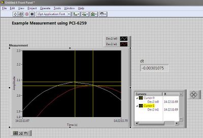
Synchronous channel multiple acquisition USB-6259 (phase measure)
Hello!
I want to create a user-signal (1 k at 20 kHz) in SignalExpress, generate it with the case NOR USB - 6259 BNC and measure with the same device after that the signal has passed a DUT I need the answer for a fixed term.
For the moment, I'm trying this: I connected the output via a Y-coax analog (length 1 meter) to TWO analog inputs.
Because the input channels have been grouped with the add a channel button, the data acquisition should occur almost synchronous.
However, sometimes the phase response is zero (cause as expected the two signals must be equal), but sometimes it "jumps" (especially when I am running the new project) and increases or decreases linearly on the frequency (so there is a time difference between two measured signals).
I don't think that running is the problem here, because referring to the manual, it's about some µseconds and I have not yet change the range of voltage between input channels. Furthermore, the magnitude response is fine.
I has not yet perform to synchronize the input channels with the output of the channels either, but first I would be recognizing a solution for the entry-entry-synchronization, (I don't mind if it is implemented in LabView).
Thanks in anticipation, Daniel
Hello Daniel,.
the M-Systems Series DAQ using a switch to sample multiple channels. So you have to take the time to switch into account when
you do measures such as phase shift of two signals.
I took your project Express of Signal but also created a LabVIEW VI to double check, and you can see exactly the same lag between the two
sampled signals. If you want to measure the true phase differences, you have to use a device of simultaneous sampling like S or DSA series devices (there are more a few others).
concerning
MArco Brauner NIG.
-
NEITHER USB-6008 can measure an AC voltage
Now I am doing a project, but don't know if DAQ can measure an AC voltage or not, the acquisition of data that we use is USB-6008.
Yes, it can measure AC in the range of +/-10 volts and have a sampling rate of 10kS/s.
Application engineer OR
-
What is the resolution for USB-6210 for positive ranges of entry?
Hello
I use USB-6210 to sample different types of sensors and each has its own range of values. I have two questions:
(a) what are the fixed beaches of USB-6210 where most suitable is chosen automatically depending on the settings of user intput scope? They are to +/-0.2, +/-1, +/-5 and + /-10?
(b) I know that if I select + / 10 as the range and then I will get the resoultion of 20 /(2^16), but what happens if I want to the positive range only? So if my sensor gives values between [0.10] and data acquisition would choose the + / 10 range. Then could get a resolution higher than 20 /(2^16) and how?
Thank you.
(a) Yes, they are the ranges listed in the manual
(b) No, a fixed range means a fixed range. You cannot change them.
-
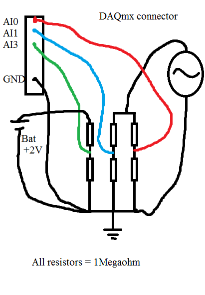
USB-6225 DAQmx measurement problems when using a voltagesplitter
Hi guys

I had a serious problem regarding the use of DAQmx USB-6225. Please look at my diagram below:
When I measure the waveform sine on AI0, everything is OK. Even with a very sampling rate high as 80kS.
When I measure the waveform sine on AI1, everything is OK. Even with a very sampling rate high as 80kS.
When I measure the battery voltage on AI2 CC, everything is OK. Even with a very sampling rate high as 80kS.
Now comes the problem:
If I measure all three analog inputs or the two and two together, I get a very different result when I measured one and a single channel. If I add more channels (i.e AI3 and AI4) on my USB-6225 DAQmx, without connect anything to them, I can see the sinuses even as I do with AI0 AI1, but with less amplitude.
When I measure the voltage as well as AI0 and/or AI1, the domain controller becomes sinus armor as well. If I connect the + 2 V DC directly to data acquisition without resistance, I see a line perfectly DC on my chart, but with the sinus AI3 and AI4 top.
If I use an oscilloscope and measured directly on the same wire that goes to my data acquisition and the resistorcoupling, I can see small pulses of the samplingfrequency and the signal seems quite noisy.
That's my big problem:
Everything works perfectly if I use R<100Kohm. any="" value="" below="" 100k="" is="" ok.="" this="" coupling="" on="" the="" schematic="" is="" just="" a="" test.="" the="" trouble="" comes="" when="" i="" need="" to="" measure="" a="" circuitboard="" that="" draws="" energy="" from="" a="" capacitors="" in="" the="" circuit.="" if="" i="" use="" any="" resistors="" below="" 1megaohm,="" it="" draws="" energy="" from="" the="" circuitboard="" and="" the="" test="" is="" not="">
Anyone with some experience around this problem? The impedance of the analog input on my USB-6225 DAQmx is 10Gigaohm so it should not really been an issue.
Here is what I tried:
With the help of a D - sub cable with shield. I tried to use with no shield shield closed, I have both ends and closed, the shield only on my DAQ.
I checked my code and also just used the DAQ assistant.
I checked all parts off my setup for groundcircuits and I twisted each cable from any power supply, the signalgenerators, the DAQ cables.
I have connected my DAQ to mainsground (in the wallcontact 230V and Yes, we use 230V in Norway). Also any other equipment.
I connected without mainsground. Also any other equipment.
I tried cables as short as possible.
I tried to use the differential, CSR (Respect to GND), NRSE (Respect to the sense of IT). Nothing has worked.
I tried to use as sample rate and samples possible. (It helped a little when the DC measurement and AN analog input. If I tried all three, he has yet again).
All this comes to mind that the USB-6225 DAQmx cannot manage measuring more than resistors with values around 1Megaohm and above.
The answers will be rewarded with congratulations and a sincierly 'Thank You '.
Hi guys again!
Bother replying this thread

I'm a guy. I don't read manuals! But now that I did... And. There are 4 pages describing my problem and what to do about it. So problem solved
I have experience ghostvoltage of the other channels due to the high - impedance of the source. I created a follower of tension with an op-amp and the problem disappeared! Thank you ni.com/info/f/. Do you have answers for everthing is there to inquire. Except why I ran out of beer. mmm beer!
-
HP Pavilion: Before port USB on HP desktop computer has stopped working
My HP desktop computer is about 2 years old and has two USB ports on the front and a number on the back. I had no problem with any of the ports until I used a USB in the port now broken and caused a power outage that now this port doesn't recognize any USB device. It says "USB device not recognized. The last USB device you connected to this computer worked badly and Windows does not recognize. »
I tried to uninstall and reinstall the USB ports on the Device Manager and have lived all the suggestions on the HP support site and the Microsoft support site. The defective USB key must have caused damage to the track. I hope you can suggest something that I can do to get it working again.
Hello
The only port on the front is damaged. The USB key must have damaged only this USB port. I'd like to reuse this memory bar.
You need to replace the USB module, two ports USB 3.0 of housing as the two front ports use the same module and connections to the motherboard.
You will probably need to go to HP for the part.
You should be able to get access to the component by removing the front bezel. Remove the side panel also. You should see the connection of the cable and add him the USB 3.0 connector front on the motherboard.
Jay
-
USB 6008 analog i/o has stopped working
Hello
I have been using a USB-6008 for a few weeks now and it has worked well. I've been using the outputs digital, analog inputs and outputs this morning and they worked very well. I worked on something else for an hour or two and then resumed using the 6008, find the analog pins have stopped working. The show output analog on 1mV any value I send to them and the analog inputs always read - 10.3, despite limits MAX being set to 0 and + 5 (and me only using 0 - 5V on them). I tried all the inputs and outputs, in all ways (CSR, diff) with the same results. The digital outputs all work very well. Yes, he is grounded properly. Yes, the wires have continuity. My multimeter don't lie about me, either.
I took the MAX test panel to solve the problems. The unit passes its tests of self-control, and my Labview program does not return errors by contacting the 6008. I don't connected the 6008 which could exceed the voltage or the current limits of entrances and exits. In fact, all I did was unplug it when I stopped using it as soon as possible and then reconnected it when I went back to work. The material to which it is connected has been turned off during this time.
Any ideas? Thank you.
Problem is solved. If anyone finds this is interested, the problem was at the level of the material, that the 6008 has been connected. I'm covering, among other things, to a PIC Microcontroller. I just changed the oscillator on the PEAK, and inadvertently changed parameters parameters of the ADC as well. This caused the pin used as my reference voltage (connected to + 2, 5V output of 6008) to transform itself into a digital camera of output, a value of 0. This short-circuit the + 2, 5V output of the 6008, causing it to close.
Lesson learned: check your material carefully, even if it does not make the difference in a first time!
-
Measurement Studio has a least-squares method to solve the multiplication of matrices?
I'm looking for a least-squares method to solve the multiplication of a matrix of 99 x 99 to a 99 vector element.
Is there a method similar to the "fminsearch' of Matlab function?
This is the method I use now...
NationalInstruments.Analysis.Math.LinearAlgebra.Multiply (InverseMatrix99x99, Vector_99)
Thank you.
To my knowledge there is not a feature that replicates Matlab function "fminsearch" in the analysis of Measurement Studio package nor is there a multiplication of matrix least-squares method. However, you could write a DLL and call it in your Measurement Studio project. LabVIEW has an implementation of "fminsearch" in its packaging MathScript. You can read the documentation on that here (http://zone.ni.com/reference/en-XX/help/371361D-01/lvtextmath/msfunc_fminsearch/).
Kind regards
Steven Zittrower
Technical sales engineer
National Instruments
Maybe you are looking for
-
What is the iTunes backup size
When I open iTunes and go to preferences and devices, it is not the size of the backup for iPad or iPhone, only date and time, what they have done. How can I find out what size these backups are on my Mac computer? Is there a file location to find ou
-
How can I watch a movie DVD on my Satellite A200-1HE with Windows XP Home edition?
Hello I bought a laptop Satellite A200-1HE and have uninstalled Windows Vista. Now I have installed my own purchased copy of Windows XP and downloaded the drivers from the Toshiba web site. But now I want to use the computer to watch DVD or write CD
-
Can I have the user enter a variable that will be used to Signal Express?
We seek to use the Signal Express to collect data of analog sensors and load cells. We would like the user to be able to enter a variable that the program Express of Signal can act on. Is it possible within Signal Express?
-
Windows File Protection dialogue Windows 2003 Server
I got an error of Windows on Windows Server 2003 File Protection. The dialog box asks for Windows Server 2003, Standard Edition CD-ROM. I didn't have one, so I downloaded a version zipped our site of Volume License, but he doesn't like it. The server
-
How can I recover photos on an external hard drive?
I have an external hard drive with photos on what I'm trying to transfer them to the hard drive on my computer?