Use ContinousPDF.vi with NXT blocks
Hi all
I'm programming an alogrithm location, which uses the ContinousPDF.vi to trace the current location of the robot that follows a Gaussian distribution. The problem is that the VI that uses the ContinousPDF.vi is developed in order to make a NXT Robot. This VI uses NXT bloks. The combination of this block with the PDF it does not work.
Is it possible to fix this?
Thank you!
Sorry, the link to the Forum does not work. I enclose a photo
Tags: NI Software
Similar Questions
-
Use the PXI-2630 terminal block in a matrix configuration?
My apologies in advance for the length of this post!

I use the PXI system with PXI-2530 switch modules, related to a series of USE with PXI-2632 (1W matrix 8 X 16) connector blocks and a PXI-4071 DMM for each switch module. My request, uses the PXI system for measurement of current and voltage external to verify and/or benefit from restraints of reliability. A requirement of the application, therefore, is that there must be a ride from DC through each USE with change of the minimum impedance as the application between its "bypass" mode switches and its mode 'measure '.
I used this Setup with connector blocks of matrix in conjunction with one of our test systems, and I am satisfied with the results. I started working with the Test System, has no easy connection to catch HAD, I needed to build a kind of interface the PXI system and a resistive faced load HAD, it was not difficult to build in the wires that attach to the Terminal screw of the 2632. He did turn into a nest of a coded son rat I did my best to keep clean and tidy in different bundles, however. Fortunately for the cable fasteners!
My next task is to use this application with system B Test, which has an interface of pines buck header with which each signal that goes to or from the DUT can be obtained. No welding or pass the wires through the openings where the designers have no intention of son to be stuffed. I intend to build a break-out Board that allows simple connections between the modules PXI and the number of Test B system which we have or will have in our laboratory. In order to simplify the configuration/installation, I want to reduce the number of connections to terminal block screw. Preferably, I would like to completely remove the screw terminals and use lever-based connections where I can't have mating of the headers. The PXI-2632 terminal blocks unfortunately use Terminal screw.
In matrix mode 8 X 16, the closing of the PXI-2530 switch kcom1, 3, 5, 7, no matter what points in the array are connected. A link between the row of right and column C is done by closing the switch corresponding to k (16R-C). I checked using the Soft Front Panel.
I also have a number of connector PXI-2630 blocks. These are intended to be used with the switch module in one of its MUX modes and include 8 banks of connections of the header 2 X 9 pins. In the the 2530 documentation and 2630, I identified that switch k-x is associated to chX output pin, ch0-15 related to the pins 1-16 from Bank 0, C16 - 31-associated pins 1-16 of Bank 1, etc.. X = 16 B + P-1. PIN 18 of each bank is used for independent MUX topology comX. Pines multiplexes sixteen seem to correspond to the sixteen columns of the matrix, with eight common lines corresponding to eight lines.
Here's what I would do, but I would like to ping the forum to see if anyone tried something similar and wisdon to share the thought:
- Make custom cables which connect the pins 1-16 of all eight banks 2630's header with a single Ribbon connections 16 son carrying the signals emitted by the interconnected banks (poles!).
- The custom cable bundle will also include a wire connected to the pin18 of each of the eight banks (line connections!)
- 24 total wires in the harness will end in the header connections who will probably partner by the lines that I currently connect to each object to be measured.
- Make additional harnesses that interface with the Test System B header pins.
- Make a map of derivation using band Council or a similar material to provide header pins to connect the two above custom cables and allow the connection of other elements such as resistors using Terminal level.
I checked this concept using the Assembly of 176 pins four terminals, like a bunch of little pieces of wire and cable. Are there other issues that I have to configure, such as the elements of a terminal that establish physical components of the switching topologies? The bowels of the PXI-2632 provide more features than the interconnection of the sets of eight sixteen pins? The bowels of the PXI-2630 connect elements that do not allow my proposed scheme?
I appreciate the suggestions and all entries!
Thank you
Jeff Zola
Hi Jeff,
First a correction to my previous post: 2632 Terminal has no reed relay protection resistors as I said earlier. The resistance that you were referring to the 2632 and those that I confused, is there to connect the columns of the switch. Resistances have a resistance value zero and act as the electrical connections. The 2632 connects columns c0 to c16, c17 c1, c2 to c18 and so on. Switch cards 2531 and 2532 have the protection relay reed on board resistors.
As for resistance in the map that protect the reed relays, they are generally very low and do not significatly affect even small tensions that pass through the switch. The resistance won't affect all currents in the map. Any effect that the resistors have on tensions will be with the precision of the switch card specifications.
Thus, to address the other issue in your post, there is no resistance in the connectors because they are not necessary.
-
Original title: lifecam 3000 and Skype does not?
Hello, I tried the two 5.5 beta and 5.3. When I try to use the webcam with Skype it blocks Skype and says "Skype has stopped working windows is checking for a solution." I have windows update connection bars 4/5 drivers and my computer ==> http://www.newegg.com/Product/Product.aspx?Item=N82E16883103361 help is appreciated, thanks
Hello, I had just fixed yesterday. I deleted the drivers and programs that accompanies it, it ends up being the lifecam software that comes with it interfering with Skype, thanks to all who help :)
-
I deleted Adobe Reader 11 and rebooted and reinstalled Adobe Reader 11 and I still get the error message "Adobe Reader is blocked because it is outdated". Using Windows XP with the latest updates (SP3).
Screenshots attached to e-mail responses will not come back on the forum. You must connect to the forum and post in your topic using the camera icon in the editor.
Google Chrome is a problem:
- If you use the clean Chrome PDF Viewer, the results are unpredictable.
- If you use the Adobe Reader with Chrome plugin, it can reject (block) If this isn't the latest version. 11.0.08 drive is the latest version for Windows XP, but Chrome can insist on the current version 11.0.10.
My suggestion; Use a different browser!
-
LabVIEW interface with multiple blocks of Festo module
I am trying to connect with a block of Festo, but I can't. Here are the details:
I'm under Labview 2012 SP1 with IndComm-DeviceNet 2.2 pilot on a 64-bit Windows OS. I installed a PCI 8532 card NOR. I see the map to the MAX.
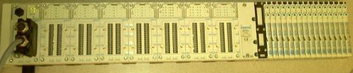
The block of Festo is built with the following Modules: CPX_FB11 (communications module), 4 analog input Modules, 1 Digital module, 2 digital modules followed by 32 Festo valves. (Image below)
Using DeviceNet PXIPCI Basics.lvproj I did the following:
In the project, right-click on desktop > New > targets and devices > existing target or device, discover an existing target or device...
Expand the node of DeviceNet Master Interface, DeviceNet1 chosen and added to the project.
A click on the newly added DeviceNet/device target > New > targets and devices...
Expanded the Festo Block "CPX_FB11" selected DeviceNet slave device and added to the project.
Initially, I received an error card technique 'EDS file no assigned' I solved this by following the direction listed here.
However, I'm unable to "see" anything other than the CPX_FB11 LabView. The tree view of the devices lists not analog, Digital e / s or valves. I can't operate the Valves and IOs digital or analog. When I run the entire project VI they then expire.
Any help would be appreciated.
Thank you
Tennessee Paul
Hi Jesse,.
I'm not entirely sure what the specific problem was. I kept getting strange behavior. Errors in LabView and on my camera from Festo. The EDS files change. So, I did as any natural born THERE would be worker, I rebooted.

Here are the steps I used to get this project going. In doing so, I found that to set up a DeviceNet device in LV2012SP1, no need to manually enter the data in file EDS. There is a tool to load files EDS. It dealt with issues I had in the previous Forum posts: here about loading files EDS in LabView and here regarding setting up a DeviceNet network.
Environment: Windows 7, 64-bit processor. IndComm 2.2 pilot. LabVIEW 2012 SP1
Starting with the example LabView project: "Devicenet PXIPCI Basic.lvproj.
Add a DeviceNet master to a LabView project
- The project: right-click on my computer
- Select new
- Select the targets and the device (s)
- Select the option "discover existing devices.
- Select the discovered device.
- Click 'OK' (Note: in this case, my master is a card PCI of NOR-8532)
Add a DeviceNet slave device to a LabView project
- Right-click on the master device newly added in the project tree
- Select new
- Select the targets and the device (s)
- Select 'discover existing devices.
- Select the discovered device.
- Click OK. (Note: in this case my slave is a block of Festo CPX-FB11.)
Load an EDS file to the slave device
- Right-click on the slave device
- Select "Sheet"... »
- Click on add files...
- Navigate to the location of the EDS file.
- Select the file.
- Click OK.
- In the left pane, expand the data sheet newly added up to reach the node displays the version.
- Select the version.
- Click OK.
Check the device and file EDS
- Right-click on the slave device
- Select utilities
- Select the Panel of Test online
- Select the option 'Device status' in the field of category on the left.
- On the right, select the slave device, you want to check.
- Click on "check the device".
- Read the errors/warnings or lack thereof.
- Navigate to the following location: C:\ProgramData\National Instruments\NI-IndComm for DeviceNet\Datasheet
- Remove the sheet (Note: there is more that one datasheet added manually.) Additional EDS files come with the IndComm driver. Find the EDS file for the specific device that you want to replace and delete).
-
Source a current Sine using USRP N210 with Labview
Hello
I use USRP N210 with boards LFTX/RX for communication (electromagnetic Induction) cable and programming using LabVIEW and downloaded the drivers. I need to order the USRP to send a signal sine of 1 MHz through the barbed wire. I used the "Sine simulation block", but I'm not sure the block to which it must be connected to. Please let me know the steps or the blocks/screws that can be useful.
Thank you.
Hi Julie,.
I think you need to use the open niusrp and log screw
You don't need to use the configuration VI signal because I think that you can not set the frequency of the carrier on the Remora LFTX and LFRX.
I think you can use the sinus blocks of generation as shown in the picture as an attachment.
Thank you.
-
problem with a block of memory in labview 2009
Hi all
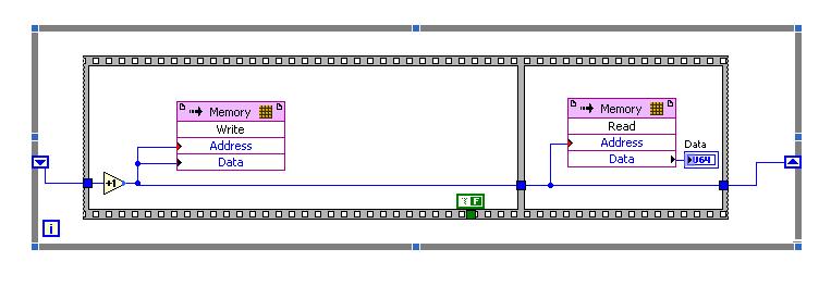
I have "ERROR: MapLib:979 - LUT4 symbol" during the compilation process (lots of errors like this), and I discovered that the reason of my problem is block of MEMORY.
To be sure that the problem is in this block, I did a very simple project in LabView 2009 (on FPGA Target PCI5640R) only with the use of this block you can see in the photo, as well as in file test_memory block.lvproj attached link: https://www.dropbox.com/sh/u87f1oihelmm4dq/Jo_6-bICSf
I have a problem with compiling VI with this block, and I have so many errors like:
ERROR: MapLib:979 - LUT4 symbol
"window/Thatcher/n_00000036/nSCTL_00000013_00000014/n_000000A3/cOutLoc<0>1.
(output = window/Thatcher/res000001ed_wi<2>) is the input signal
"window/Thatcher/res0000020d_wo<1>" that will be deleted. See Section 5 of the
Map a report file to find out why the input signal will become conveyors.or
ERROR: MapLib:978 - LUT4 symbol
"window/Thatcher/n_00000036/nSCTL_00000013_00000014/n_000000A3/cOutLoc<23>1.
(output = window/Thatcher/res000001ed_wi<25>) is an equation that uses
input pin I2, which no longer has a connected signal. Make sure that all the
the pins used in the equation for this LUT are signals that are not cut
(see Section 5 of the report file map for details on which signals were
adjusted).Entire report, you can see in the file report.txt on the attached link.
I would appreciate if someone could take a look at my problem with simple project and suggest me a solution.
I'm really stuck with my biggest project which need to have this memory block.
I'm looking forward to hear from you,
King looks
ING. Damir Hamidovic
Hi all
I find a sollution to my problem.
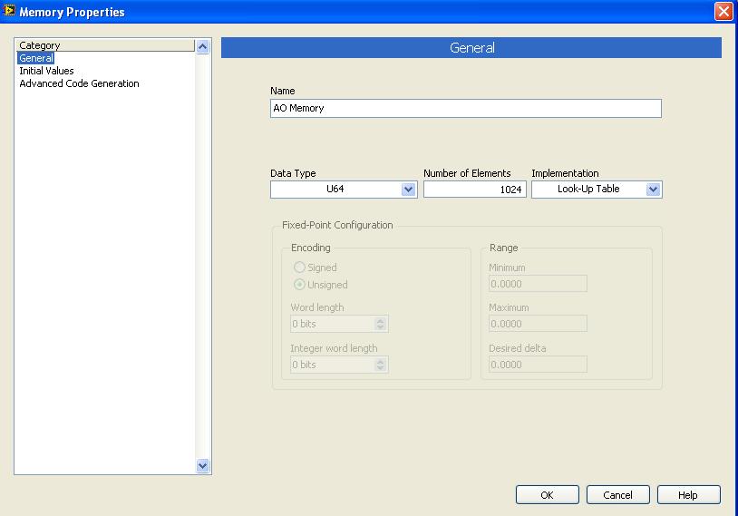
In memory-properties-general-setting up, I changed the block to look up Table memory, and I compile memory.vi and run it successfully.
I did change as you can see on the picture:
Just, can you tell me is it all "bad properties" and limits the use of this type of memory (Look up Table) of the implementation?
King looks
-
Using DAQ Assistant with a system remotely
I'm new to LabVIEW and National Instruments hardware and I am trying to use an instrument with LabVIEW using the DAQ Assistant. I use a PC with Windows Vista and I am connected via a network to a PXI-8108 controller in a PXI-1050 chasiss chassis. The instrument is just a thermocouple which I use to become familiar with everything. The thermocouple is connected and the connection SCB-68 block which is connected to a PXI-6221 multifunction data acquisition in the chassis. I am able to create a task in MAX under remote system and everything seems to work. What I want to do is to use this instrument in LabVIEW, and it seems that for this I need to use the DAQ Assistant, but when I do it says no supported device is found. I wonder if there is a way to get LabVIEW lean on the remote system to see the acquisition of data and the thermocouple.
All advice is appreciated.
Thank you
Hi all
Ben is correct. RDA is no longer supported in DAQmx. We have another way to use DAQmx with a remote system. It is use DAQmx with an OPC server or simply by shared network variables. There is a section of the base of knowledge here that should help you get started. You should also take a look at the developer section area here. The basic idea is that you can use a variable shared within labVIEW that is bound to a variable shared on your networked machine. In this way, you can write and read values from a task DAQmx. Look at the instructions in the above two items and let me know if you have any questions.
Kind regards
Paul C.
-
Increase the capacity of data store, which with the block size?
Hello
I am trying to expand my datastore 2 TB, I added a new lun 2 TB of the FC SAN TB 4 even and there is no problem adding this in the existing data store.
But the existing data store is formatted in VMFS3 with a block size of 4 MB for a maximum file size of 512 GB. But when I try to extend the data store to select the size of the block is set to 1 MB and disabled.
The measure automatically takes on the size of the original block or wil he get a block size of 1 MB? There are some > 256GB files on the existing data store and I think I'd get a strange behavior, if half of the data store is 4 MB and the other half is 1 MB blocksize.Can anyone confirm that the blocksize wil be the same for the measure?
I can also make a second warehouse 2 TB one manually fracture the virtual machine on 2 data warehouses. is there any advantages or disadvantages to this approach?
Don't you worry, add an item to an existing data store certainly will not change the size of the block. In any case, if it is an option that you can use two data warehouses, I would. With two distinct data warehouses that you will not only be able to spread the load on each of these LUNS but also avoid the complexity. With ESXi 5 (VMFS-5), a single LUN can grow up to 64 ~ to without needing extensions.
BTW, a 4MB block size allows 1 TB less than 512 bytes.
André
-
How to enable tracking changes with pfile block
Hello
I want to use enable followed the change block (for fast incremental backup RMAN). kindly advice how can I use this setting using pfile.
Thank you
KrishnaHas nothing to do with the pfile. Just issue the sqlplus command:
alter database enable block change tracking; -
Uniform measurement and measure / HWM - why I'm left with 24 blocks?
Hi guys,.
Recently, I have the busy table a few hundred megabytes, even after I have truncate and deallocate unused.
So I decided to publish this statement to remove freespace under the HWM.
< i > alter table ain.scb_grp_user_priority DESALLOUER UNUSED KEEP 1 K; < /i >
When this statement is complete, I question this
< i > select nom_segment, segment_type, bytes/1024/1024, blocks, nom_tablespace in dba_segments where nom_tablespace = 'AIN_CC' and nom_segment = 'SCB_GRP_USER_PRIORITY' order by desc bytes; < /i >
SCB_GRP_USER_PRIORITY TABLE 0,1875 < b > < /b > 24
I know that I am always left with 24 blocks.
1st quarter), I said to keep 1 K, why am I always stayed with 24 blocks * 8192 bytes which is more then 1 k?
Q2) how can I find out the number of block by default measure?
whenever I create a table without no storage clause or change the table allocate extend, the amount of added block = 8.
(3) I am using a locally managed tablespace, then I believe that measure allocated are uniform in size.
When I check the table dba_extents
Select the nom_segment owner, segment_type, nom_tablespace, extent_id, bytes, blocks from dba_extents where nom_segment = 'SCB_GRP_USER_PRIORITY' and owner is 'AIN ';
AIN SCB_GRP_USER_PRIORITY TABLE 0 196608 24 AIN_CC
I saw EXTEND_ID 0 with 24 blocks.
There should not be 3 extend, each with 8 blocks?
Kind regards
NoobHemant K Chitale wrote:
where I ended up with a measure of 320K, if I started with INITIAL 128 M, the next 64M (although the 'next' should not important?)
in 11.2.0.1It would be 32 level 1 bitmap blocks, one level 2 bitmap block, the segment header and six other hand to get a multiple of 8 blocks.
Which is consistent with the scope of 64 MB you created probably because of your initials. Here is a comment about by bitmap blocks a couple of years on the newsgroups: http://groups.google.com/group/comp.databases.oracle.server/msg/e23f811e4786ef0f?hl=en
Rgards
Jonathan Lewis -
Can I upgrade to iOS 10 using a Mac with OS (10.8.5) Mountain Lion?
Can someone tell me if I can sync to my iPhone 6 with iTunes using a Mac with the (10.8.5) Mountain Lion?
This is what Apple is the list for the iPhone 7 that runs iOS 10.
http://www.Apple.com/iPhone-7/specs/
- Sync with iTunes on a Mac or a PC requires:
- Mac: OS X v10.9 or later
- PC: Windows 7 or later
- iTunes 12.5 or later (free download from www.itunes.com/download)
My daughter is running Lion on his MacBook Pro and was synchronize its iOS iOS 9.3.5 devices. The requirements for iOS 9 call for Cougar 10.8.5. It will never update via iTunes - always on WiFi - and I think that's how she got away with it. I don't know if it will work this time with iOS 10.
- Sync with iTunes on a Mac or a PC requires:
-
Try to add a page to a pages document. It worked until now but just finished page 13 with text and photos and cannot add another page, using macbook pro with El Capitan and the most recent version of the Pages.
You have placed your beam to insert at the end of your text on page 13 and then apply Insert menu: Page Break? In the v5.6.2, Pages I just add a new page to a section of four pages to this approach.
-
I use an iMac with a wrong as a monitor graphics card?
The graphics card on my iMac went wrong. The logic board is OK and works otherwise OK. Can I use the iMac with the graphics card bad as a second monitor in target disk Mode or use it as a monitor for a mac mini? The bad iMac is a model 2011 (of course!) with HDMI ports and Thunderbolt.
I think you mean that the Display Mode target and any connection to the screen will have to pass by the graphics card. Whereas if you replace the bad graphics card, don't.
-
Using Migration Assistant with no display
I got my MacBook mid-2010 (2.4 GHz, 4 GB RAM, OS X El Capitan) for 2 years.
It splits into two somewhere within 2 years.
The MacBook was still usable, but it had to be on a desk. The screen was completely separate from the base. It still worked.
I woke up a few days ago to find that someone had cut the display cable holding the MacBook set and turn on the screen.
I bought an early-2011 13 "MacBook Pro to replace the dead MacBook. (Yes, I buy old Mac because the news is so expensive).
Old Mac has been saved semi regularly, so I have an old backup to use for the new Mac. The problem is that just before the death of the former Mac, I downloaded a bunch of stuff that has not been saved. I really want the files that have not been backed up on my new MBP.
Can I use Migration Wizard with an Ethernet cable and transfer of data from one, or Migration Assistant must be running on old Mac as well?
I tried to connect (I'm sure that the computer is still running, it doesn't simply have a display) on the old Mac, plug the backup drive and I hope to do a backup hourly, but Time Machine did not only.
Any suggestions would be GREATLY appreciated.
If you use Ethernet or a wireless network to transfer data, Yes. If you can not download the files and file-sharing has not been activated on the old Mac, you must either get fixed display or put its internal drive in a closed Chamber.
(143074)
In my case I had errors in my EDS file. Basically the slave device was not defined for the correct number of bytes of input/output in the EDS, i.e. a wrong configuration file. To fix this I had to change the EDS file.
Edit the file EDS
To change the EDS file, I used EZ-EDS , which is a freeware, devicenet specific EDS editor of ODVA.
I did my corrections and saved my file EDS. (After having saved my original, of course).
Remove the installed Labview EDS file
I restarted LabView.
I went through the steps above again and loaded my new EDS file.
I saved the project and came out of LabView.
I rebooted the computer and the slave device.
I restarted the project and launched a VI.
I was able to communicate with the device. That is something that I had not been able to do before. And, in doing so, I discovered how the device speak and why were not each module. (I have a standard for my block devices EDS file, as it appears that LabVIEW is not capable of a modular system that requires an EDS file for each module. I could be wrong on that last part though, as there may be a setting on my real device. But it is unecssary in my project. So I do not consider this further.) Because I was using a standard file of the EDS, only a single slave device showed, and so the data for each module are in the stream of bytes returned to the DeviceNet network. Addressing each module is a question of analysis the bits and the bytes appropriate.
Thank you
Tennessee Paul
Maybe you are looking for
-
The AirPod will work with the iPod 5th generation?
Thank you.
-
Advice of failure - time for an update system - Qosmio G15 HARD drive please
Hey people, Thus, it seems that my C drive died on my G15. I managed to recover most of my data and I am always under scans now. However, I don't think that I can trust the machine and bought a new hard drive. Now things are messy to messier. Apparen
-
does not appear bluetooth icon
I am using hp pavilion model 15n 260 tx with win 8.1 I don't get anywhere bluetooth icon in my notebook.
-
I have recently installed SP2 for Vista, since then I had problems with access to programs and applications. When I try, I get this message, telling me that I have a problem with the windows Explorer and click to solve the problem or click here to v
-
Why the "send this Page / link by e-mail" are gray out?
Why the ' file - > Page / link by e-mail "are gray out? I use Win 8.1 (x 64) with IE 11. Window live mail has already been set as a default for the reading of e-mail files. Grateful if someone could give advice to the problem. wosozeng