Using clock_gettime to measure the execution time is back from the strange results
struct timespec start, stop;
If (clock_gettime (CLOCK_REALTIME & start) == - 1).
{
fprintf (stderr, "ERROR SETTING TIME");
}
... the long-running...
If (clock_gettime (CLOCK_REALTIME & stop) == - 1).
{
fprintf (stderr, "ERROR SETTING TIME2");
}
fprintf (stderr, "time: %f", (double) (stop.tv_nsec - start.tv_nsec) / 1000000000.0F (double));
It helps to surround something that takes about 3 seconds to run translates into an output such as:
Time:-0.743363
What gives?
Are you sure tv_sec is not necessary? I could be wrong, but it seems to have the number of seconds since the epoch, followed by the number of nanoseconds up to the next second. If you compare just nanoseconds, you might be in a different second. E.g. 5000000nano-> 200000nano 11s 10s.
Tags: BlackBerry Developers
Similar Questions
-
How to use Labview for measuring the reflectance at different wavelengths automatically
Hello!
I'm using labview to communicate with MS257 (a monochromator). If I do not use Labview, I have to use the hand controller (set a wavelength from 300 to 1100 under a grating (a total of four grids).) It takes a lot of time. So I want to use labview to realize the automation. But I don't know how to do, I still can put only a wavelength as a command for MS257, not making any difference.
Does anyone know how to deal with this?
Thank you for your time.
So where are you stuck? It is a fairly common task. Inside of a loop, you can increment the "xxx" and build a table of responses. Look at the Format function in the chain and a knot of shift register/feedback.
-
How to use photoshop to measure the amount of shades of Brown in a given area (Immunohistochemistry)
I try to use photoshop measure intensity area of brownish (some variance) in a part of the image of a mouse knee joint. I have stained a particular marker in these samples and hoped I could quantify because she is extracellular and discreet
Thank you!
Scott, I believe that I came up with a way for you to make selections within your settings and have prepared an example to demonstrate the method. Much depends on whether this technique, using your spot color and a specimen, will work. If so, you can measure the number of pixels in the selection following the instructions I provided previously. Here goes:
1. This sample represents the darker brown spot.

2 build a scale of gray similar to this (I can provide one shown here)

3 Edition > fill with your Brown sample more dark and set its blend Mode to color. (When I used the sample in step 1, this was the result.)

4 attach it to your specimen as shown image file here. (I have not colorized that half of the test image to demonstrate the next step only select the sample Brown even if the black & white area has the same tone value.)

5. with the magic wand, a tolerance of zero and contiguous unchecked value, when you click on a box in the balance its corresponding value will be selected in the image. Here is an example. The histogram can then be used for a number of pixels from all selected areas. Repeat for each sample in your settings.

I hope it does the job for you.
[(Edit: quand vous arrivez àles valeurs plus sombres, vous pouvez constater qu'augmenter la tolérance contribue à la couverture de l'écart entre valeurs.)]
-
How do Parameters.Result used as a reminder? How is it different from Parameters.Step.Result?
Hello
I searched reference manuals TestStand, help and the forums, and I have not yet found exactly how Parameters.Result should be used in callbacks (if at all).
I am trying to find a way to take a step that normally is not registered in the list of results and force it to appear on the rare occasions that it will fail. I think I should use the result, but I don't know how. If I set Parameters.Step.RecordResult = True, then the step attaches to record results, but which seems to be permanent in the sequence file, and AFTER THAT failure becomes declared.
Thank you for your expert help!
-Gizmogal
By browsing the SequenceFilePostResultListEntry I finally discern the difference between Parameters.Step.Result and Parameters.Result, which is visible at run time:
Parameters.Result has a TS container, which refers to the stage, giving information such as StepGroup, StepName, StepType, among others. Its results-oriented properties are identical to the Parameters.Step.Result properties, I can say.
Parameters.Step.Result has a container TS large type TEInf that seems to be the test information administration.
There seems little back than I expected, but that's it.
I'm partially through to shift my paradigm - save all the results and then throw those no interest. I ended up adding a status string 'RecordAlways' to force certain steps to record each time, and I throw any which are not equal to or 'Pass', 'Fail', 'Error' or 'done '. It works pretty well so far.
Thanks again for your help!
-Gizmogal
-
How to measure the execution time of a specific to a VI process?
Hello! My VI has two processes: compression and edge detection image and I'm trying to measure the execution time for the process of detection of edge of my VI, but I don't know how to do. Please give me some ideas on how to do it. Thank you!
There are several ways that you can do.
-L' one is using the number of cycles before and after your vi to get time like here: http://digital.ni.com/public.nsf/allkb/6F6B9F4E149C80578625652800784764
- or use the profiling: https://zone.ni.com/reference/en-XX/help/371361H-01/lvhowto/profiling_vis/
Edit: If you're open to suggestions:
-You have not to load the image inside the loop instead, make him outside of the loop.
- And I see of many IMAQ buffers are not removed properly. You can have everything at once by Images (No) by logging in to Boolean TRUE: http://zone.ni.com/reference/en-XX/help/370281P-01/imaqvision/imaq_dispose/
-
Measure the time of the rising edges of a digital stream using a USB-6341
I have a DAQ USB-6341 map.
I use Measurement Studio (writing code in c#) on a Windows 7 computer.
I'm relatively new to the DAQ cards, programming, so I could ask something that is obvious (sorry if this is the case).
I went out a stream of digital pulses to an analog output channel. I wired this channel to one input of the meter channel. I am able to measure the number of edges upward to the inlet of the meter channel (since the digial flow is continuous, the number of rising edges increases with time).
I would like a time stamp of each rising transition and I like to keep these timestamps in a table without ever growing (or maybe bin these timestamps in a histogram).
Set up the meter channel to provide the timestamp data? (rather than just count)
Thank you for your help.
WRB,
The meter must be able to measure the relative time between the different edges of your signal. To do this, you will take care to set the meter to measure time. It will measure how long a full period of your signal takes. You can configure edge that you want to start with. You'll want to set up your timed 'implied' measure. This sets up the meter to automatically take action whenever a period is over. While it's not exactly a timestamp, you can find the distance between two edges by adding the time periods between the banks in question.
I see another technique that you can use. This would put the counter to edges of County one of the basics of time of your device (it has 100 KHz, 20 MHz and 100 MHz bases long). Then configure the task to use your signal as a sample (configuration to use rising edge) clock. Whenever the song occurs, you will get the number of ticks ticks selected timebase that took place at that time. One thing to note here, however, is that the counters are 32-bit wide, so your code will have to manage the overthrow of this charge if you are using a fast time and base running for long periods of time.
Hope that helps,
Dan
-
How can I measure the time between the two edges of successive increase, using digital input...
Hello
I'm trying to measure the time in seconds between each two successive rising edges on a digital input.
So far I managed to detect the rising edge, increment a counter at each rising edge and take the time during which the increase is edge
all I need now is subtract edge currently rising from the previous era of edge rising to calculate (T), which can be 1/frequency and display in real time for the user.
but I do not know how to do this

Can someone help me please!
Note: while I am in a position varies between 200 ms - 2 seconds
-
How can I measure the time between each two successive increase edges, using digital input?
Hello
I have tried two measure the time in seconds between each two successive rising edges on a digital input.
So far I managed to detect the rising edge, increment a counter at each rising edge and take the time during which the increase is edge
all I need now is subtract edge currently rising from the previous era of edge rising to calculate (T), which can be 1/frequency and display in real time for the user.
but I do not know how to do this
Can someone help me please!
Woah!

Sorry Apok, but your code becomes much too complicated and salty. I don't think that all records to offset or Boolean conversion/operators are necessary at all.
If you want to measure the time between two keys so it's another (much less complicated) way. It simply records the time when press button in a registry change, then compares the two.
-
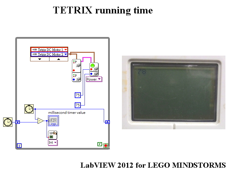
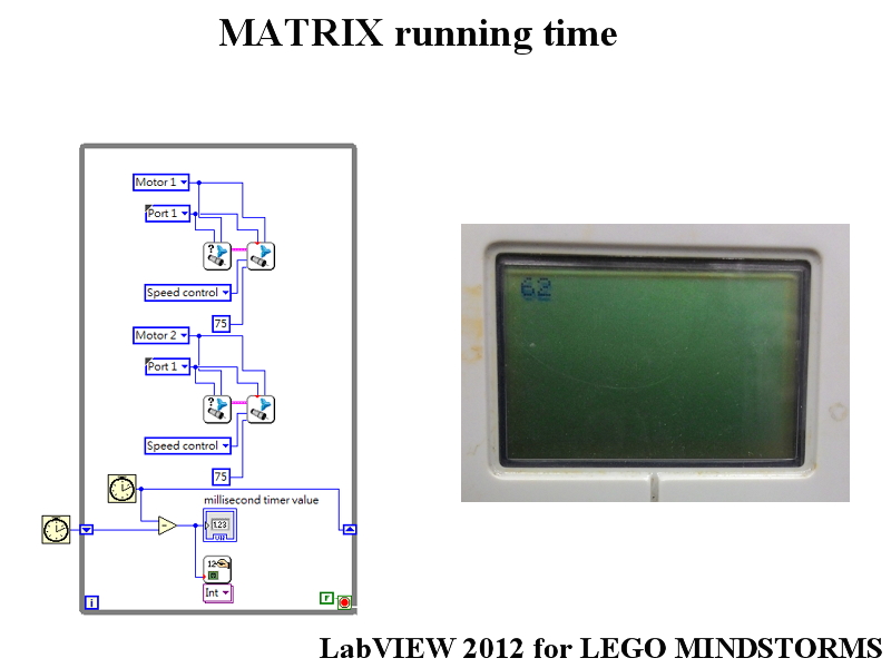
How to shorten the execution time of the NXT (TETRIX & MATRIX toolkit) brick
Hello
How to shorten the execution time of the NXT brick?
(TETRIX & MATRIX toolkit, running time)
The software is 2012 LabVIEW for LEGO MINDSTORMS
Thank you.
Hi 40123157,
You use the module in an appropriate manner, and there is no simple way to improve the time of loop iteration beyond what you've done. Here are my suggestions:
(1) the i2c commands take a long time. In your application, it may speed up if you run only move the engine only when the engine speed has changed.
(2) for this particular example, you do not use the release of the report engine. If this VI does not need to run it can be removed.
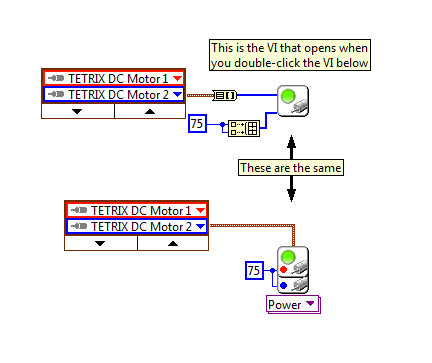
(3) If you need to speed up execution other than that, as a user advanced LabVIEW, you can create a copy of the VI of engines to move and change it as you choose. All you have to to the "DC motors' entry is use cluster to array on the cluster, as shown below. I think you can speed it up by running all the settings before the loop (type sensor and fixed connection configuration), and removing the value of power if you send only the values between-100 and 100.
(4) drawing on the screen can be slow you down here.
-
How to calculate the execution time of a SCTL in FPGA VI?
Hello
Can someone guide me that how to calculate the execution time of a SCTL for an iteration in the FPGA VI?
Thank you and best regards,
Rashid
Hello r,.
A SCTL will always run in a beat the clock it has been linked to. So, if you use a 40 MHz clock, this loop will run in 25 ns. If the code cannot complete in that, or if it requires two graduations of the watch to do the calculation, your code does not compile, then you have the guarantee that this will always be how long it takes this piece of code to run.
-
Measure the time in seconds each time run you a VI
Dear people,
I'm trying to measure the speed of a wheel using a magnetic sensor and other settings in the vehicle. What I also need to document in my project is the time elapsed (in seconds) each time that you run the program. Is there a way where you can measure the elapsed time in seconds in labview?
Any sort of suggestions or examples would be useful.
Below is an example of how I wanted my final to watch output file.
Time (sec) | Speed (mph). Acceleration |
0 23 5
1 24 6
2 25 7
Thank you in advance!
Rahul-
Hi iZACHdx,
That's what I was looking for exactly! Thanks for the simple example.
Thank you
Piraux
-
Measure the current and voltage using DMM sharing a port
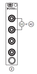
I want to measure pressure several times on a pcb, where I connect the ports of digital multimeters to the card using simple cards. Switching between the different voltages is done using simple. If the black port of DMM (the second from the top photo) is connected to the Earth to give the measure correct volt.
And then I want to measure current through different lines. The problem is here. Given that two measurement types share a port, how do I get the correct voltage and current measurement? The second port of top would be grounded, so I can't use the method of measuring the voltage across the line through a resistance with a known value, since then the second port must not be connected to the ground. How can I use the current state of the DMM measurement? How measure current? Are there examples of this? Tried looking through manuals, but could not find the good starting points.
so I can't use the method of measuring the voltage across the line through a resistance with a known value, since then the second port must not be connected to the ground.
On all of my games to test I have to mux my land of the signal along with the salvation of my signals.
All my mux test sets are set up for the topology 2-wire because there is no other way to do it without the weak side of switch also.
-
Hallo,
I use the following system:
- OR PXI-1044 with controller NI PXI-8109
- OR PXI-2564 switch module to turn on the monitor of my test device
- Data acquisition multifunction NI PXI-6259 to measure the signal that responded to the questionnaire jump
The two cards are the same - PXI trigger bus. For both, PXI-2564 and PXI-6259 I use DAQmx to set the reading and writing of the channels.
Now, I want to measure the time between the digital output, my unit turns and the analog input, which measures the response of my system.
I can't do work by myself, please help me!
I thank Ludwig.
Hi Ludwig,.
If you can't give us any VI we have difficulties with to help you.
Because I Donat knowledge how your program is mounted it is not easy to know where you should enter signals.
Here's a question similar to yours:
http://forums.NI.com/T5/LabVIEW/best-way-to-measure-time/TD-p/178704
and 2 external links:
http://www.ehow.com/how_8698983_measure-time-LabVIEW.html
http://objectmix.com/LabVIEW/385152-how-can-i-use-LabVIEW-measure-time-between-analog-pulses.html
-
Measure the time between the ridges of the periodic input signal
We have built a circuit which is supposed to mimic an Exercycle. We have an IR switch and a spinning wheel, the rccb meets a comparator circuit and the output of the element of comparison, we have running in LabView. We successfully were able to measure the number of rotations of the wheel and the total distance travelled by the wheel, but are struggling to measure speed. We cannot find a way to measure the time between picks in real time, which we could then divide the wheel circumference and calculate the speed in real time. The VI I posted has a square wave simulated rather than the signal we receive on our circuit. Thanks in advance for the help.
Jon and David
I think you're overloading the things trying to get the time between two pulses. Instead, you can use the VI Express your measures and select frequency for her custom. Then, you can multiply the circumference of the wheel of the frequency to get the speed.
I hope this helps.
-Christina
-
Measure the voltage and the temperature at the same time with a single card PCI 6014 DAQ?
Hello guys,.
I'm doing a charger measuring the voltage of the battery, the charge current and the temperature of the battery using a 6014 cardboard...
I want to use my PCI6014 DAQ card to measure 2-channel analog voltage input and 1 temperature Channel Analog input using thermocouple type k measurement of voltage or temperature isolation is OK, but I can't understand how to measure the voltage and the temperature at the same time... I want to use input differential...
Thank you in advance, all the tips
YSL
Create a task and add channels to the task, as follows:
Christian


Maybe you are looking for
-
Unable to get the computer out of safe mode
Remove my computer in Mode safe and return it to a Normal Mode * original title - get my computer out of safe MODE and return to a NORMAL MODE. I almost tried everything and I hate the thoughts to start over and lose all my info computers *.
-
LOCKED ADMINISTRATER. FORGOTTEN PASSWORD AND NO DISC RESET.
I have NEED of HELP RESETING ADMIN PASSWORD as soon as possible
-
How do you get $_SESSION vars in jquery mobile
Hello everyone. I'm creating a mobile application with jquery. I have created.a connection format that uses getJSON() to validate the connection with photos. If successful the login.html redirects to the loggedin.html. I kept the name of user in. A s
-
I have a new acer aspire V7 nitro. It is came with (ugh) windows 8.1 which would not be the programs that I need for work. I loaded windows 7. The problem I have is windows think the touchpad is generic and charge the mouse HID-complaint. I down
-
Connectivity Internet randomly loses
Original title: internet connectivity Hi friends, when I connect with an internet connection run quitely and after 40 minutes, it's to close automatically, just after disconect I again to connect to the net it is easily quitelly running, but still 40