Using NI 9512 with Modulation of frequency step Position? (cRIO)
I am trying to activate a scene for an experience that requires a frequency on the step signal modulation to a stepper motor. I use a cRIO-9076, a NO-9512 and driver to drive stepper P70530 OR third party engine step by step. step VI FM Position seems to be exactly what I need for my application, but I have some difficulty working with him and the NI 9512.
Is it possible to use the 9512 in an FPGA VI? THE ETC. requires use in a single-cycle timed loop, so I want to send the step and Direction signals directly to the FPGA of e/s for the 9512. The 9512, however, does not set up to use FPGA to IO. In research, I found some examples using the 9501 instead of the 9512 module, but this would require a lot of new material that I don't think I should buy.
I would greatly appreciate some suggestions as to what to do and even of ideas as to how I could fix this problem.
Thank you
Enan
Hi Enan,
When you use the 9512 in scan mode, the NI SoftMotion Module will send a position setpoint at 9512 once each evaluation period (the period of analysis is usually around 1 to 10 msec). The 9512 does not generate a path; It just interpolates between the values given. It is your responsibility as the programmer to ensure that values being sent to the 9512 are sinusoidal. To do this, the easiest method is to use a contour move and fill the contour buffer with a profile of the sine wave. You can generate a sine wave using something like the model sine VI profile. He ship in SoftMotion examples that show how to perform a move of contour.
In my view, contours movement require SoftMotion Standard or Softmotion Premium. If you have SoftMotion Lite, the only way to get a real path sine wave is to build the model of the sine wave on the host of the RT and send him to the FPGAS in a FIFO. You could also build the model of the sine wave directly on the FPGA. You will then write the sine wave point by point to the Write 9512 method. It is more difficult to achieve, so if you have SoftMotion Standard or Premium, I would recommend the move approach outline.
Thank you
Tags: NI Hardware
Similar Questions
-
Use the same code module to multiple steps in the sequence
Hi all
I tried to implement a sequence that uses the same code for all steps module in the order, but I'm not returning to it when I need to send it commands. I got regarding the appellant the VI in a new thread so that it can be executed asynchronously. I can run the simple sequence and it will indeed open the VI and move to the next step. When I close the VI manually from the front, the TestStand sequence is completed, as planned. So it turns out that I have a lot more work.
My question is how to call the thread separate from the main sequence and other sequences overtime when I need to change the settings. If I insert a step in the Action, I have to select a file of VI, but from what I can tell, it opens another instance of the file and does not provide an interface with the other asycronously running instance. My next guess was to use a stage of education, but I was not able to understand how to configure the search string to call the VI settings. In addition, I don't know how to proceed. Please notify.
My intention is to start the module code (asynchronously) VI, run several different subsequences in the main sequence, which call this same VI and edit its settings, close everything and report the results. If I'm understand how TestStand is supposed to work, please let me know.
Thank you
GSinMN
What I do is use a queue to send data to the asynchronous VI. So he can run and whatever, but also receive orders from the queue. I use a motor of Action that contains the reference to queue and sends the commands. If you really just call the engine of the Action of your sequences.
-
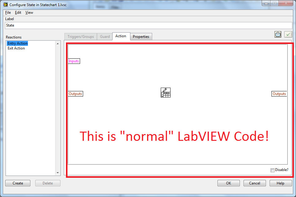
ISI t possible to use several screws with state diagram module
Hello
I'm doing a request using the module state diagram, and I have to use at least for VI I developed. I have problems when I want to set the entries before creating different States. My VI have stop buttons and the e/s I need to use. I have the same problem with the outputs. Because I can not set the input/output (type moore machine) I can't nor define the guards and actions that the state machine must fallow.
You have an idea if we can use several VI with this module or do I have to use the good old box + all state machine technique.
Thank you.
Of course, this is possible.
hope this helps,
Norbert
-
I use a PC with Windows 10 and Lightroom 6.1.1. As soon as I want to move from a photo retouched to another in the develop Module, Lightroom freezes. Can you help me?
Hi Petra,
> Try disabling the option of GPU in the Lightroom > edit > Preferences > Performance tab
> Update your graphics card driver
Hope this helps
~ Assani
-
Using Acrobat XI with IE11 and Win7; I can't the acrobat toolbar. Watch modules Manager he's here and activated, but the toolbar is not there. And when I use right click and click on convert to Adobe pdf format, nothing happens.
Can anyone help?
Hi Richard,
1. start Internet Explorer.
2. Select Tools > Internet Options, and then click the Advanced tab.
3. check if "enable third-party browser extensions (requires restart)" and click OK.
4. close all Internet Explorer Windows.
5 restart Internet Explorer.
Let us know how it goes.
You can also check out the following link and see.
Quick fix | See a PDF on the Web
Concerning
Sukrit diallo
-
Returned by DAQmxGetDevCIMaxTimebase for a NI 9361 module incorrect frequency limit
Hello
I have a NI 9361 module in a 9178 cDAQ chassis. My workflow is as follows:
(1) create a new task
(2) add a the meter inlet channel to the task
(3) the maximum basic rate of time meter using DAQmxGetDevCIMaxTimebase entry question.
(4) set the sampling frequency clock using DAQmxSetSampClkRate at the speed required in step 3.
(5) Perform other steps such as add a channel of analog input or external clock to the task.
I get an error in step 4:
Requested value is not supported for this property value. The value of the property may be invalid because it is in conflict with another property.
Property: DAQmx_SampClk_Rate
Required value: 100.0e6
Maximum value: 40.0e6
Minimum value: 22.250739e - 309
Why step 3 returns 100.0e6 when I put only a maximum of 40.0e6? Must I call another method instead of DAQmxGetDevCIMaxTimebase? I have attached my code for your reference.
Thank you
Varun heraud
The MathWorksThere is a difference in how the counters work for the 9361 NOR in the cDAQ and counters in other devices (including the cDAQ chassis counters). The 9361 OR use a chassis timing engine, so it does not require an external sample clock, and it transfers data to the bottom of basket on each sample clock. Therefore, there is a limitation on how fast that can occur and the DAQmxGetSampClkMaxRate function allows users to query this value. The counters on the USB-6211 USB 6351 require an external sample clock, and since they are one of the subsystems of the device, the maximum sampling rate is not dependent on engine, no data transfer time constraints so DAQmx does not support the property of max (for the tasks of meter) sample rate. For these devices, you get an error if the counters have no new data between the sample clocks (because the sample clock is faster than on the counter source input signal).
-
Source a current Sine using USRP N210 with Labview
Hello
I use USRP N210 with boards LFTX/RX for communication (electromagnetic Induction) cable and programming using LabVIEW and downloaded the drivers. I need to order the USRP to send a signal sine of 1 MHz through the barbed wire. I used the "Sine simulation block", but I'm not sure the block to which it must be connected to. Please let me know the steps or the blocks/screws that can be useful.
Thank you.
Hi Julie,.
I think you need to use the open niusrp and log screw
You don't need to use the configuration VI signal because I think that you can not set the frequency of the carrier on the Remora LFTX and LFRX.
I think you can use the sinus blocks of generation as shown in the picture as an attachment.
Thank you.
-
external frequency step-down converter
Hello
1. I have a digitizer 5142 with a resolution of 14 (16) bit. can I change this rate of 8-bit scanning, or can I get a signal to 8 bits using 5142 I
think I can using neither scope config. If yes also means I increased the speed of 200MBS 100MBS (since I am only
using 8-bit scanning). increases the speed of transfer of the data from my memory shipped to hardisk only or both are applicable
2 - I read this specification 5142 when I stumbled upon two things that I surrounded as JPG attachments
a. filter anit-alisasing has a bandwidth of 40 Mhz, and default 5142 uses what it means. Can I use
some other external down converter instead of 5600 and which can acqiure 40 Mhz bandwidth at any center frequency and I can feed to
5142 to get digitized and writre a file on my disk. .i can't use DAMA since I use a step-down external frequency converter. How using or
scope/tuner vi.
(b) the other is true flat bandwidth = 0.4 * rate and bandwidth flat complex sample = 0.8 * sampling frequency that we mean by these two.
Concerning
MADD
Hi malala.
1. correct me if I'm wrong. Insofar as I have defended frequency translation means that if I have acquired a signal at 50 MHZ with a 40 MHZ Bandwidth (F_high = 70 Mhz and F_low = 30 Mhz). My frequency step-down converter. If I select the option enable translation frequency and frequency set to 20 MHZ (option to activate with the SDC thus) signal that I have gained is now translated to 20 MHz (C.F), the maximum frequency to 40 Mhz and Minimum to 0 Mhz. Is it so? If this is correct, then I think that my Ghost will meet the requirement of the spectrum of nyquist and won't be mitigated...
Not quite fact-frequency translation used to take your signal of a certain frequency IF complex base band (centered around 0 Hz). If you set your frequency of 20 MHz, 20 MHz will tune to your NCO and you will acquire some bandwidth, based on IQ rates, around this central frequency. For example, if you used 20 MHz bandwidth (rate of IQ = 25. MECH / s) and a center frequency of 20 MHz, get you 10 MHz to 30 MHz of frequency and translate this to baseband. Now you have your frequency content at +/-10 MHz.
To do what you seem to want to do, you must set your frequency to 50 MHz as well as your IQ rate to 1.25xBW = 50 MECH. / s. This will mean your 40 MHz BW from 50 MHz to complex baseband.
2. also mention that I can put this decimation is property invoke node or filter specifications.
Decimation is another property of the OSP and the mechanism of the clock. Your decimation is defined by your IQ rate compared to your time base sample clock. For example, by default, we use a time base 100 MECH. / s for the 5142. If I put my IQ rate 2 MECH. / s, I will use a factor of the decimation of 50. Our table of decimation emphasises, however, that, in the range of 12 to 4 096, we can only use decimation integers that are multiples of four. So, we will eventually be forced in this case to 48 and a sampling rate of 2.0833 MECH. / s. You can then perform resampling to 2 MECH. / s in the software.
3 - something else enable and disable the noise/anti-aliasing filter. Combination of maximum frequency of niscope configuration characteristic.vi. If I put it in noise filter 20 Mhz is on now and when I started 35 Mhz filter anti-aliasing is enabled. Is it so?
That's right - your maximum frequency setting to be in one of these filters will allow this way. If I put a maximum frequency of 19 MHz, the filter is activated. If I put a max of 30 MHz frequency, the Anti-aliasing filter is enabled. 0 will default, and -1 will allow full BW.
Kind regards
-
Using the output with 6009 or 6216 possible buffer?
Hello
I have a USB6009 and a USB6216. I need to generate a signal by using the analog output and I would use the output buffer. My questions are:
-The USB6009 has an output buffer? I always get an error, but I know from experience that this device is very limited, so I wonder if they have not only an output buffer... (Programs in input buffer are not a problem at all).
-J' took the USB6216 and I tried the example WfmGenUp.c downloaded from somewhere in the area of the developer (sorry I lost the link but fix the code) but I am not all analog output signals and after you press ENTER to stop the program (depending on the show) I get this error message:
NO MORTALS RUN - TIME ERROR: 'WfmGenUp.c', line 113, col 9, id thread 0x0000088C: DAQmxStopTask function: (is-200016 return value [0xfffcf2b0]). Measurements: On-board memory precision passing. Due to the limitations of system and/or the bandwidth of the bus, the driver could not write data to the device fast enough to track the rate of output of the device. Reduce your sampling rate, change the method of transfer of data (from interruptions on DMA), use a product with more on-board memory or reduce the number of programs that your computer runs simultaneously. Task name: _unnamedTask<0> Code of State:-200016
I don't know if the problem is just that the 6216 does not support the output buffering or the other...
-So, if the output control is not supported by 6009 or 6216 what would be the best way to constantly generate signals to 100 s/s?
Thank you very much
Kristel
Hi Ryan,
the USB-6009 case has 150 s/s softwaretimed AO, so you won´t be able to use AO stamped with the module.
The USB-6216 supported in the analog output buffer, just follow the recommendations that the driver gives you,
for example by reducing the sampling frequency, if there is an overflow memory due to the limitations of system and/or the bandwidth of the bus.
Experiment with the parameters and the basic to see in what range of sampling it works.
You can find appropriate examples
ANSI C:
C:\Dokumente und All Anwendungsdaten Users\Dokumente\National Instruments\NI - DAQ\Beispiele\DAQmx C\Analog Out\Generate Voltage\Cont Gen Volt Wfm - Int Clk ANSI
LabWindows CVI:
C:\Dokumente und Users\Dokumente\National Instruments\CVI\samples\DAQmx\Analog Out\Generate Voltage\Cont Gen Volt Wfm - Int Clk Anwendungsdaten All
-
How can I restart with modules & active extensions?
I rebooted with modules & extensions disabled. How can I turn it back on them?
Hi jimaskew42,
It seems that you started your browser Firefox mode without failure:
You can exit the Safe Mode by following the steps in this article:
Please let us know if this solves your problem, or if you have any other questions.
Thank you!!
-Ralph
-
I don't understand why I can't login my account using mozilla but with googlechrome fb, I am able to do... Mozilla can load the fb site but cannot access my fb account... I'm uncomfortable with the use of mozilla as my browser... pls help thanks
- "Clear the Cache": Tools > Options > advanced > network > storage (Cache) offline: 'clear now '.
- 'Delete Cookies' of sites that cause problems: Tools > Options > privacy > Cookies: "show the Cookies".
Start Firefox in Firefox to solve the issues in Safe Mode to check if one of the Add-ons is the cause of the problem (switch to the DEFAULT theme: Tools > Modules > themes).
- Makes no changes on the start safe mode window.
See:
-
Can I use PC400 RAM with the Tecra A4 (Pentrium 750)
Can I use PC400 RAM with the Tecra A4 (Pentrium 750), currently PC333 is mounted.
Thank you
I put t know if you can use but AFAIK Toshiba recommends using these modules on the Tecra A4:
PC2700 256 MB (PA3311U - 2M 25)
PC2700 512 MB (PA3312U - 2M 51)
1024MO PC2700 (PA3313U-2M1G)Here are the modules of single channel 166 MHz DDR333/PC2700, DDR SDRAM, 200-pin SoDIMM.
-
How can I use your bluetooth with my Satellite L650D - 14L devices?
Please can someone help me on how I can use your bluetooth with my Satellite L650D - 14L devices?
I don't see a bluetooth icon helping manange bluetooth connections.Thanks for your help.
ConcerningHello
You cannot connect any BT device for this laptop because it was not equipped with any BT module.
BT is therefore not available for this device. -
Question about the use of the memory modules
I have a dilemma between the use of a new 1 GB memory (what I intend to buy) with more speed
and by using the 1 GB + my old 256 with less speed
which option will contribute more?Hello
The fact is that if you use 2 different memory modules with different properties (of lower performance) so the laptop can run with lower performance. This means that the 256 memory module slows down you memory. The best way is to use the same modules having the same properties.
-
Physical connections using 4 counters with NI 9411 cDAQ chassis 9178
Hello
Currently I have a NI 9411 module in a 9178 cDAQ chassis. I use 2 meter to read the frequency measures.
The NI 9411 pinout diagram (see pdf file attached to this post), here are the links that I did:
CTR 0 SRC, pin 1 ground COM
DOOR of the CTR 0, pin 2 to the first signal of frequency
CTR 1 CBC, PIN 6 COM/ground
CTR 1 DOOR, pin 01:53 frequency signal
The problem now is that I had like to use meters of 3rd and 4th in my 9178 cDAQ chassis, but I am confused how to wire
frequency signals in 3rd and 4th, because CTR2 GATE is pin 1 and GATE CTR3 is pin 6. Can I change the assignment of pins
to use the other pins in the NI 9411 module for frequency counter measures? I didn't understand how to do this in MAX
Configuration.
Thank you
Anna
Hi EETDer,
Using 'C-Series Signal connections for counters that you found is a good resource. One thing I want to point out, that's a measure of the frequency on a single meter, simply connect the source of the signal up to the door of the RTC. Internally, the module will forward a database internal time appropriate to the source of counters, so DO NOT want to connect the Source CTR to the mass. On your device, you will be just wire each signal to the source of the meter, so only utilizting pines 1,6,3,8 for your 4 frequency measurements.
Maybe you are looking for
-
Single window has no buttons. Why?
I have four windows open in Firefox. (I can't tell what version: 'about' box disappeared.) "But I'm trying to install all updates). Three windows are fine, but the fourth window is missing the red, yellow and green candydrop round buttons on its uppe
-
Hi, I could not connect my pavilion dv6 2113tx Samsung tv using ch I have cable. When I ran the diagnostics I found this driver base system were missing for 3 and an ene cir receiver driver is missing too. The device base system Id are as shown below
-
The Autorouter of preprocessing error.
Hello Earlier, I make a big enough drawing in Ultiboard. My drawing is composed of 4 layers. Upper, lower and internal 2. I use the inner layers to Vcc and GND. Now, I want the rest of the nets to be connected using copper top and bottom copper. Afte
-
Invisable external hard drives
My PC stopped showing my 2 of my external hard drives in Windows 7 Explorer. They are visible if I use the installation of "remove hardware", also on the control panel > Administration > management of the computer and at least one program. They are c
-
How can I change the default file format?
HelloI've recently updated to CS6 CC. When you use CS6, the default file format is PSD but CC use TIF and I couldn't find a way to change this behavior. Any tips? THX and regards