Using simulate arbitrary signals
Is it possible to import more than 100 samples with the VI express to simulate arbitrary signals? When I try to "load data" in the signal screen set it is important only 100 lines
You are 100 samples of playing at a time and put them in a single file?
Somehow, you had 100 samples written in the file at the moment that the header has been created, but a 38 000 added another samples after that. If you change the 100 at 38100 in the header of this text file, you will see all of your points added.
Tags: NI Software
Similar Questions
-
Hello
I would create a program that simulates the signal given by the contraction of a heart Chamber. It should be periodic with an adjustable frequency and amplitude. I use a structure of the event with a time-out interval equal to the time interval of the signal and a block "simulate arbitrary signals." The problem arises when the signal trace because the graph shows all forms of wave side by side instead of not not been zero only after than all of the time interval. You will find attached an example of signal I would get and that I receive and the labview VI.
I hope my question is clear, thank you in advance for the help.
Federico
So, you want something like that?

-
Unable to send arbitrary signals of CC. Help. Please, I beg you.
Hello people,
I am a student of Btech working with Labview 2013. I managed to generate an arbitrary Signal through Labview 2013 version for my project. Now, I need to send the signal to Agilent 6642 power supply dc to ampilfication and it will be used for my experience. I am facing problem here.
I use GPIB USB HS to send the signal, and when I send commands * IDN, is successfully reading and writing, which means I have all my software and drivers installed perfectly. I have installed in my pc control expert and NI MAX.
I did a program (which is attached) in labview and the GPIB seems to read (signal ACTIVE/Green shows when it is executed).
But I do not see it in the oscilloscope (Tektronix TDS 2024 B) which means something's wrong here. I need to see the signal as shown in the attached picture.I am new to labview and don't know much. Please help me with the Labview program as I want to see the signal in the oscilloscope as well.
If a command is needed, let me know the order.
I'm stuck. Help, please.
Thank you.
-
Example of arbitrary signals fgen does not
Hello
I use an example of NOR-FGEN - "any arbitrary signals." I want to activate the digital filter, but there is an error occurred. What should I do to fix this error?
bahec666,
The SMU-5451 does not support a digital filtering. That's why you get the error message that you are experiencing.
-
generators of PXI arbitrary signals compatible with the generation of ssb vi
There of SSB generation vi, what Arb. People of waveform. will work for the PXI system? 54xx?
Here is a list of our arbitrary signal generators that this vi should work with:
NEITHER 5411, 5412, 5421, 5432, 5441, 5442, 5450 and 5451
-
example 2-channel oscilloscope VI using real-world signals
I'm looking for an 2 oscilloscope channels VI that uses real-world signals, not simulated signals used by "two Chennel Oscilloscope.vi' I found under examples when I searched"Scope"or"oscilloscope ".
I found on a site OR "One_Channel_Simple_Scope.llb". I think he uses real-world signals. I downloaded it but not able to run the VI. When I tried to do, it didn't compile successfully. The error messages were several subVIs are not found: DAQmx read.vi, DAQmx timing.vi, etc. I have LV 8.6 and NI 6221 Multifunction DAQ card, installed in a standard configutration in an environment of Winows Vista. I define a variable say LV path where to find these screws?
Thank you.
Not a sampling frequency is high, but this uses entries of the sound card on L and R for 2 channels:
http://decibel.NI.com/content/docs/doc-4834
Have you installed traditional data acquisition and not the more recent style DAQmx drivers? Maybe it's the source of your mistakes.
-AK2DM
-
Hello, I'm trying this arbitrary signal by arbitrary simulation of output signals express VI. I want an exit point out analog of the DAQ USB 6281 every second. When I said to output a point by iteration I get error 200609 say the selected buffer size is too small (selected the size of the buffer: 1, minimum buffer size: 2) how can I change the buffer size? attached if my VI, just go under the 1 'arbitrary' case and you'll see my VI Express with points iv series.
But you are passing an array many points so you should have to index this table point by point by putting the DAQ Assistant, in a loop with a delay of 1 sec. You can also spend the whole wave and specify a frequency of 1 Hz in the DAQ Assistant.
-
Better to use an arbitrary primary key?
Hi all
I have an employee table where each employee has a unique employee ID. I expect to look up employees by their ID frequently. Is it better to use an arbitrary sequence as the primary key and put an index on the field ID employee or to the employee ID primary key? Thanks for your help.Welcome to the forum!
>
Is it better to use an arbitrary sequence as the primary key and put an index on the field ID employee or to the employee ID primary key?
>
Best practice is to use surrogate keys (for example, your arbitrary sequence) rather than actual data (employee ID) for the key field values.The main reason is that the values of data, data, maybe should be changed in the future. If you use a piece of data as the primary key and then must change any changes becomes problematic if there are references to foreign keys to it.
Another reason is that these references to foreign keys mean that the value of data is now duplicated and exist in several tables. It should be changed in any of these tables.
And business rules to deal with employee ID (or any other value of data) may change. It may be encrypted or protected against access by unauthorized persons. If ID is a primary key, because it is much more difficult to encrypt or protect the value is necessary to join the tables correctly and will therefore always available for the purpose of the request, even by people who are not allowed to access the value actually.
Never use values of actual data for values of key with the exception of the simple sample applications.
-
PXI-5421 generating an arbitrary signals on the fly
I have a card PXI-5421. I need to generate an arbitrary waveform with different frequencies. I need to have a trigger to switch between Forms of waves of different frequencies. I use the script to do this. I'm not able to update the frequency of the next wave on the fly without stopping the program. In other words, can I download signals in real time? The code is attached.
Hey Kakrott,
You should be able to achieve this with your PXI-5421. The example of 'switch between the waveforms FGEN"in the examples of LabVIEW makes something similar to what you're trying to do. As explained in the documentation: "this example shows how to switch between two different wave forms while generating, using updated data every time." This example uses a trigger to change what waveform is generated.
-
How to use an analog signal to conditionally generate a TTL (or a square function) signal?
Hello world
I am using PCI-6229 and try to develop a code that can generate a TTL/place function signal from only one analog entry satisfies following conditions: 1. crossing a certain value (for example, 0 V); 2 slope edge of fall. The time delay between the point of passage and newly generated signal TTL/square will be essential to my measurement, and may not exceed 1 millisecond. Any suggestion on this subject? Thank you in advance!
You are using the measure called Excel add-in? That's what this forum is for. Otherwise, you should post to the multifunction DAQ card and speak the language you are using.
-
Problem updating my state machine, using the emg signal
Hello
I have problems with my code. My entry is an EMG signal that I gather from three different electrodes using usb 6008. In the program, I divide the signals and display them in a chart that is unique. What I want now is to read the signal, and if a signal passes a threshold I want an LED lights. This must remain lit until there is another signal that passes the threshold.
To put it simply: "large enough signal--> lamp on--> stay informed--> enough large signal--> lamp--> stay off the coast and then start again."
I tried a few different approaches, but I decided using a state machine. Now, the problem is that when the signal to enter the state machine the program crashes. I think it's because the table that I use to convert the signals does not update when I get my state machine, so the signal stops to come. But how to get around this problem? It is even possible to code what I want?
I have attached the code. All the tips are welcome, I have been struggling with this for some time now.
Thank you
jenmich
The problem is internal while the loop is run until the stop condition is true, but he never does a new Boolean entry. So that it remains for always in the same State. Remove the inner loop and put the shift register on the outer loop instead.
You must also use a daqmx configures the element, and then set the properties of daq. The read.vi can be set to read a number of samples of each iteration.
Also: you can expand the table to index for several items of output. If you want that element number 0, 1, and 2, you have yet to wire the index entries

-
Machine using LabView trigger signal
The company I work for has just acquired a new machine which measure the size of the particles and other variables. The machine is supplied with its own program that records and analyzes the data. However, we want to get around that and read the data directly in LabView and so be able to filter, organize, and sort as desired.
Attached are pictures of the configuration of the machine. The red circle indicates the cable that connects the PC to the machine.
While the machine will operate its own, there will be no signals transmitted to the PC without a trigger command. It's my first question: how to provide the appropriate command of LabView machine so he can generate the right signals.
The manufacturer of the machine:
The colloidal Dynamics AcoustoSizer (AZRII) consists of a central processing Signal (EPSC) and unit of different sensors, shown in figure 2.1. They are controlled by the application owner software that is running on a classical computer in MS WindowsTM based (PC).
Under the direction of the application, the EPSC generates pulses of sinusoidal voltage on a sequence of prescribed frequencies between 1 to 20 MHz. These pulses are applied to the sound Amplitude Electrokinetic and mitigation sensor (ESA), where they generate ultrasonic signals in the colloid.
These signals of ultrasounic, which contain information about the size of the particles and the load, is converted to voltage pulses by mitigation ESA probe sensors, and impulses are then directed to the EPSC for the signal processing. The processed signals are transmitted to the computer, as well as data from the pH, temperature and conductivity sensors. At the end of the measurement phase, the data are analyzed in the PC to determine the particle size and zeta potential.
Information on the measurement process:
A typical measurement sequence is as follows:
The PC issues instructions for the EPSC applied pulses of high voltage excitation frequencies prescribed the probe to ESA/mitigation. This is according to two modes, the ESA, and mitigation.
The extent of the ESA, this voltage pulse is applied between two flat and parallel electrodes that are in contact with the suspension. The suspension runs vertically upward between the electrodes with a brace polyphenylenesulphide (PPS), the ESA probe. One of the electrodes is adsorbed on an acoustic delay line, opposite which is mounted a ultrasonic transducer thin. The applied voltage pulse causes the colloidal particles (which are almost always electrically) to shake back and forth. This query generates sound waves, a phenomenon called the Amplitude sound Electrokinetic, or the effect of the ESA. The sound waves of the ESA spending since the suspension along the glass delay line. When they reach the end of the delay line, the soundwaves created tension through the transducer. The voltage pulse then crosses the EPSC signal processing circuit. The Fourier transform of the pulse is determined by the EPSC and then transmitted to the computer. This Fourier transform is a complex number with the two amagnitude and phase (or argument).
At present, we are measuring to thirteen different frequencies, at the end of the sequence of ESA measure we have so thirteen amplitudes of ESA and thirteen phases stored in the PC. This set of quantities is called the spectrum of ESA.
The extent of the sound attenuation of the output pulse EPSC is applied to a piezoelectric transducer. This generates a pulse of sound wave which passes through suspension. This impulse and various reflections that come further in time are all measured, stored and analysed using the Fourier Transforms as in ESA measures.
At the moment, that we measure to 13 different frequencies, at the end of the sequence of mitigation so we have amplitudes of mitigation thirteen and thirteen phases stored in the PC. This set of quantities is called the spectrum of mitigation.
Any help would be greatly appreciated!
Kalyie wrote:
The company I work for has just acquired a new machine which measure the size of the particles and other variables. The machine is supplied with its own program that records and analyzes the data. However, we want to get around that and read the data directly in LabView and so be able to filter, organize, and sort as desired.
Attached are pictures of the configuration of the machine. The red circle indicates the cable that connects the PC to the machine.
While the machine will operate its own, there will be no signals transmitted to the PC without a trigger command. It's my first question: how to provide the appropriate command of LabView machine so he can generate the right signals.
Well, which depends on the Protocol of the machine. Do you have the link susanianak provided that help any? You will need to check the documentation mfg on the appropriate command to send to start the cycle. This can be done easily with LV, but it needs to work with the Protocol set by the seller. Your photo shows what appears to be a serial cable. Use the VISA for this.
I didn't see a second question. Are you asking how to acquire information from the machine? If you can find a driver for this hardware, as suggested SusanianaK, which would be preferable. You can build your own. Since it's RS - 232, it sends the information in a serial data stream. Refer to the doc for the equipment to see what are the parameters of the series. If all goes well, your controller can work as a host and got the info as it comes. But there may be a set of commands supported to extract it.
-
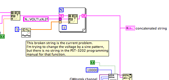
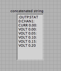
How to vary the tension of a current source continuous using a sinusoidal signal on LabVIEW?
Hi all! I have a programmable supply of GW Instek PST - 3202 DC. I want to test the resolution of temperature based on my power supply fluctuations. I started to write a VI to do this, but I don't know how to vary the tension the sine wave-shaped. I found the Wfm sinusoidal function in Signal Processing, but I don't know how to change the '1 d of double picture' which is the "double sink" waveform, which is where I apply the supply voltage waveform. The VI is attached.
The value of Format function will not accept a table, put it inside a loop. Use a shift register to add all the values in the table, to the string.
Lynn
-
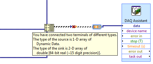
How to use generate multiple signals on a single DAQ Assistant
I am trying to generate several AO on my DAQ card, but I kept getting an error. I looked at the error and he said that I had to use a single DAQ Assistant. So, I created one, but I can't understand how to connect the signals. I get lines that don't connect. Is attached a picture of the installation. Thank you!!!
If you want to use the type of dynamic data, you must use the appropriate function. Do not use the construction. Use the Signal to merge. Then wire you the output of said directly to the Assistant.
-
Can I use five differential signals analog usb 6008?
Hello!
I have the USB-6008 housing with one and two potentiometers temperature sensor (and one meter and digital input is also beign used).
I've only got analog +-left slot but I still need to connect the voltage and current signals of a diet. Is it possible to have both connected somehow to the last + slot?
If it is not possible what harware would you recommend instead of the 6008?
6211 next best step up that gets you more AI.
Alternately, you could just put a 2nd 6008 in the system... certainly cheaper than a 621 x.
Maybe you are looking for
-
Reset the SMC on Macbook 13 inch 2013 retina
I just reset the SGC of my retina 2013 macbook, I bought there a little more than two years. Lately, it's been slow and fans have worked very hard, even though I have only run programs like Microsoft Word and Spotify. Suddenly, he showed "service bat
-
I can't connect to Vcenter using vsphere client
I installed vCenter 6.0 and vsphere client 6.0. I can connect to the web client, but when I am connected to vCenter using vsphere client I got error.In vsphere version 5.5 I can connect to vCenter using vsphere client 5.5.I can't find any information
-
Extend the existing under certain conditions drive and add if no disc
Here's what I'm trying to achieve.increase the disk space on a drive (drive C - D) especially if they are smaller than a standard value of the particular companydetect if there is a 2nd drive or not and if not then add a 3rd discOptional:(a) extend t
-
Doubt com rede (tranferencia) speed
OLA pessoal, tudo bem?Gostaria of depower uma doubt that faz tempo EU tenho, recetemente EU I bought Doi servidores Dell T410, ambos com Plaça Giga, I bought um Giga switch da 3COM, e engracado quando mando archives of um para o outro a speed not bat