Using step by step as an encoder motor
IAM using 4 engine not unipolar stepper to coil with 48 poles, and I found that I can use another engine step by step as an encoder. IAM working on a project of education - and the equipment that I have is Council NI ELVIS with Labview data acquisition... I need to know what steps I have to take to use another engine step by step as an encoder.
Thank you
Hey SK0480,
You can do this, but you have to build other circuits. Here's a simple circuit using 2 comparators. This pattern can also be useful for you. Hope that helps!
Tags: NI Software
Similar Questions
-
He said: your trial period has expired. To continue using the software Adobe After Effects; Encode; Photoshop... buy it. Is that my package is at least a year and paid every month on my credit card. I need to use it and I'm not. I can't talk to anyone... Please, I beg you! Need help.
Hello
Please see the below help documents:
Applications creative Cloud back in test mode after an update until 2015 for CC
You can also see the thread where the issue has been addressed: creative software says cloud my free trial has expired, but I have a paid subscription
Kind regards
Sheena
-
Step by step with NI 9503 motor control: cycle of use can be 50%
Hello world
I am using the module NOR 9503 with a cRIO 9006 to control an engine step by step using this module to rotatate a number of measures (480 steps) can change the direction of rotation. The frequency of the signals phase should be 200 Hz. What I need is a simple open-loop drive. No need to torque smoothing, anti-resonance coefficients, angle of correction... etc.
I tried using the example project in Labview "NOR 9503 Stepper point Position Drive". I changed so that I could set the market factor for each phase as a parameter (to 50%). Please find attached my project.
The question is when I run it, generated signals have the duty of less than 50% of the cycle. You can find oscilloscope capture in the folder "Capture". I don't know what the problem is. Please help me. Thank you very much.
I have the Labview 2014 and SoftMotion toolkit.
Best regards
Hi Paul,.
Thak you for your help.
My need is to drive an engine with 200 Hz frequency. Generate an output signal that will have this frequency playing on its cyclical report? The idea is to generate a 2 kHz PWM signal and run of 99% for a half of the period (2.5ms at 200 Hz) and then change the operating factor to 0% for the second half of the period. and so on. I think that in this way we have a resulting signal of 200 Hz.
But the challenge is to know how to generated 4 output signals? and how to change the direction of rotation?
Best regards
Lahcen
---------------------------------
-
using steps to resize the image of different size for a standard size
Hello
I have a variety of images of different dimensions. Each has a logo in it. Y at - it no way to have the application via an action acknowledge what is the logo and what isn't?
Thank you!
Actions cannot use logic. Scripts Photoshop can. But other than grateful name would be a task,
-
Using more 4 for MyRIO quadrature encoder inputs
Hello
I am doing a project where I need to drive 6 motors, each with feedback from encoder quadrature to control the position.
Currently, I use the VI MyRIO encoder, but there is a limit to 4 encoders. What is the best way to read 6 encoders simultaneously with the MyRIO?
Thank you
Timothy
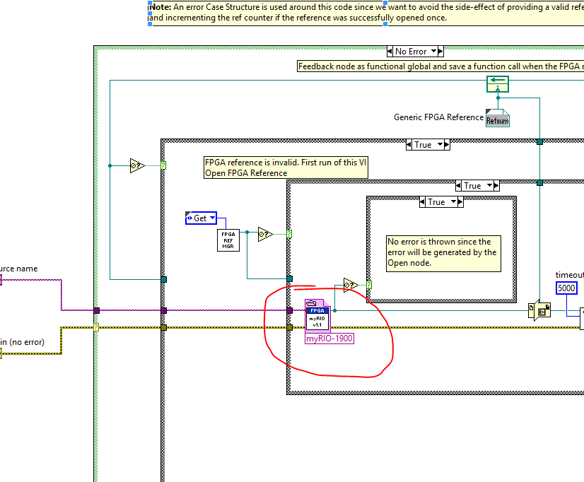
If you must change the FPGA myRIO personality you have a few options.
The best option is to start with the FPGA myRIO sample project, add and delete components according to the needs and then build your bitfile. No registry (LV FPGA control / indicators) you do not change will still work with the Advanced IO screws and screw Express. To use the new bitfile (FPGA personality) you must update the Reference of VI FPGA opened in myRIO Open.vi v1.1 (LabVIEW 2013\vi.lib\myRIO\Common\Instrument Driver Framework\myRIO v1.0\myRIO v1.1 Open.vi).
After having done all this time, you use an Express VI myRIO or Advanced IO VI it will use your custom bitfile. All peripheral channels that you left in place will continue to work. You have deleted all channels will always appear in the screws, but will not work (they will probably throw errors when running) and all new channels that you added appear in the screw . New channels, you will need to use FPGA read / write nodes for read and write configuration data and register you created in the FPGA personality. These changes will persist on this computer until you change the Reference of VI open FPGA to the bitfile original.
Let us know if you have any questions about all of this.
Thank you!
-Sam K
Join us / follow theGroup of pirates of LabVIEW on google +
-
Problems with encoder motor switching noise readings
Hi all
I wanted to ask advice with a hardware problem which seems to be pretty common.
Here I describe my request:
We are controlling an electric actuator for robotics application. We use encoders to take position readings, and we need to perform analog acquisition for other measures (for example, the force measured using strain gauges).
The problem is:
In summary, I have problems to properly acquire position readings of a linear encoders quadrature and also a few analog inputs. The cause is the switching noise generated by the drive motor that we use (which is an engine without Stricker of CC Moog BN-23-23).
Our acquisition platform is an NI PXI-8106 with a PXI-1042 q chassis. We have two possibilities to acquire the signals. We have a multifunction DAQ series NI PXI-6259 M and a FlexRIO NI PXI-7951R with one module DIO NI PXI-6581R.
The switching noise have a frequency of 30 kHz. In a scope, we see a series of peaks of noise which are present only during a short period of time (approximately 1/10th of the duration of the noise). The rest of the time the noise is not present.
The Accelnet amplification module that powers the electric motor gives us a clock signal synchronized with the noise (whose frequency is approximately 1/4 frequency noise). This clock signal provides a way to solve the problem of analog acquisition. We can use this clock to make an acquisition stamped with an external clock in LabView connecting the clock on a spit of PFI or FPGA card. But the noise is also corrupt this clock signal (we get an error daqmx us warning of possible defects in the clock signal and also to stop the acquisition). I believe that to solve the problem of encoder we can also solve the problem of the analog acquisition.
In the encoder readings noise makes our County to counter upward or backward gradually fast enough. We can get an increase in the position of about 10 cm per second with no appreciable movement in the linear actuator.
It would be a great help if someone could put the solution he uses to solve this problem.
Thanks in advance for your help,
jespestana
PS: I stress my conviction that we have a hardware problem, because we have only bad readings when the electric motor does not work. I am therefore convinced because we have already done reading encoder and analog with the help of other players, such as hydraulic cylinders. So, I think that it is not a problem with our software (of our LabView VI).
Hi jespestana,
I don't know why the noise could be the cause of your encoder can increase more slowly... However I have a suggestion on the map of the M series (6259):
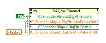
M-series cards have a digital filter integrated on the lines of the PFI (see the user manual of M series). Looks like the noise is a series of 3 ~ US of impulses (1/10 to 1/30 kHz). Of the available filtering frequencies that you can set on your M series is 6,425 US, which must ignore the impulses (high or low) that are less than 6,425 US. You can configure the digital filtering with a property node DAQmx:
One caveat is that the driver only allows you to configure the digital filtering for entries counter on M Series devices. For example, you can use a digital filtering directly on your task of encoder, but not for your sample clock HAVE. A workaround can be found here, which is to set up a dummy counter job to define the PFI filter for your task to HAVE. If you use the same PFI line for your encoder and the task to HAVE it, you should be able to just set up the PFI filter through the task of the encoder and worry for the workaround.
Regarding the RIO Flex, I think that you could implement something similar on the FPGA, but I'm probably not the best person to comment on this subject. It would be probably a lot more work to use the DAQmx API's built-in filtering.
Best regards
-
Use the angular position of the encoder to trigger Digital out
Hello
I am a novice user of labview, I have access to three modules, two NI9201 and a NI9401.
I have an angular encoder is used to measure the angular position of a crankshaft of engine, what I try to do is to use the encoder to trigger a digital camera (spark in the motor event) at a certain angular position. For example, I would like to start up (or) stalled, then I want to change that to + 5 degrees on the encoder, etc.
So far, I am able to read in the angular encoder when the engine is running, I am also able to output digital signals even if I can't find a way to connect the two.
If anyone has an idea how to do this, it would be greatly appreciated, I am attaching my VI.
Thanks in advance,
Nick
Hi Nick,
I hope that the vi attached you will get on the right track. It's just a general concept.
The while loop will work until you press the stop button.
I guess you'll need a spark by revoultion.
This VI is really just an If/Then
If the encoder value is equal to (in this example) zero,.
Trigger digital output.
I know that I have a wire cut, but I didn't know how to get the angular position of you DAQmx.
Let me know if this help. (Also let me know if I'm off-target)
Good luck
Bill
-
capture data using writing to the file position encoder
Hello dear Sir
can anyone help to check with my encoder to measure data?
I connect the writing to the file of the measurement, but when I open the .txt file,.
no result is, thank you very much for your help
-
management of the script errors when using the step of the call placed
I have a script which is activated by a trigger of jtapi. At some point places the caller on hold, makes a call using step Place call, plays a prompt and then terminates the call.
If the trigger (first contact) hangs up when the phone for the second contact rings, when the second contact answers the phone plays the default script or "Sorry we currently live the problems of the system."
Here's what I did (without success) to try to get around it: changed the default script for the application (do not know why it does not work.) This logic is invoked in a subflow, maybe that's the problem?), placed a Terminate step for the second contact in case of square step call, put in a bunch of steps On Error Goto who attend a stage finish to the second contact.
Brandon, until the original caller is replaced, an 'exception' will be thrown.
To make up for it, to the step "On Exception GoTo" > choose the ContactInactiveException > choose the label you want the call to go into the script > clears the exception (on no exception) and then play your .wav file (sorry, the band hung up.. blah, blah) > and then terminate.
who should git'r done.
Pleae rate useful positions.
-
How to operate continuously the ' frequency with digitizer step-down converter external vi "?
Hello
I use SMU-5663 on SMU-1075 chassis. My goal is to use "step-down with digitizer external .vi" in order to run the SMU-6901 frequency continuous step-down converter. To do this, I added a while loop to the provided sample (see file attachment). The problem is that the while loop does not change; the program stops as soon as its launch.
Is there anyone who can help me with this you problem?Hello
The 'get frequency response' VI aims to help correct the answer of the step-down in the acquired data. The response of the step-down changes only with frequency and reference level. In your VI, you are in a loop when you call 'Get frequency response' but do not change the frequency or level baseline for the release of the VI will not change.
To use the external digitizer, you want to adjust the center frequency and level in DAMA reference, read the frequency response and frequency step-down converter win in DAMA, to acquire data starting from the external digitizer and correct using the frequency response of the step-down, and win. You can loop through the acquisition and treatment portions until you change the central frequency or reference level.
-
Remove additional results of the previous step
Hello world
I have a step of the 'statement' (step 1) inside a while loop that creates an additional result to the stage (using Step.AdditionalResults.CustomResults.Insert). For each row in the While loop this 'statement' step will create a new additional result. After step 1, I want to delete the additional result created in step 1. If I don't delete it, after each loop my report file will include all previous results additional loop.
Is there a way to remove the additional result created in step 1?
Thank you very much!
Review the attached file in sequence. Why don't you just use the same result? Why do you need to insert and remove every time?
Can you send me this sequence you sent the screenshot? This way I can get a better feel what you are doing.
-
NI Stepper drive is compatible with NEMA 11 both NEMA 42 engines step by step?
I have an NI PXI-7350(Motion Controller), a UMI7774 or (Universal Interface), and a (Stepper Drive) P70530 NOR and tried to connect the new NEMA 11 stepper motor actuator linear Hayden Kirk and kept getting a constant red flashing light on the driver. I then plugged my new actuator linear motor NEMA 23 stepper Hayden Kirk and the pilot got the green light ahead go and it worked fine. I consulted the manual and saw that the driver was compatible NEMA 17-34 Steps. I tried the third affecting both the NEMA 11, nothing helps. Does anyone know a player NI Stepper, which is compatible with my UMI and motion controller and is also compatible with a NEMA 11 and NEMA 42 (another engine step by step I need) stepper motors?
Hello T.I.
It is true that our engine controls step by step only have been evaluated and tested for engines not to not NEMA 17, 23 and 34 size. I personally haven't seen or worked with readers with the NEMA 11 or 42 engines step by step, but given that NEMA standards are only a standard size, as long as your engines are under tension, power and plug for your engines to P7000 series inductance, walk, then they should be able to work.
-
Step property loader to load all limits in all sequences in a Seq file
Hello
I have a Seq file. There are several sequences in this file. I can export all limits in all sequences of this file as an Excel file.
My question is how to import all limits in all sequences of this file by using step property Loader. I am attaching a file seq example below (version TS3.5). Will you please show me an example to do (i.e. *.seq or screenshots are appreciated.)
From the link below, it shows that for import limits in each sequence, there must be a property Loader step in each sequence to load limits for this specific sequence. But it's annoying and not effective because the same step is performed repeatedly.
http://forums.NI.com/NI/board/message?board.ID=330&requireLogin=false&thread.ID=6522
We hope to hear from someone soon.
Concerning
Lee
Hello
The Committee for dialogue on what I was talking about is the feeder of property change (see table). Typically, you use this after you insert a step PropertyLoader Type in the installation of the PropertyLoader step sequence statically. General, you set many of the properties statically and then change one or two of the properties programmatically. Unless of course you're generating the entire sequencefile programmatically.
The properties that you need the installation would be Step.Sequence = "
", but also you must set Step.UseCurrentSequenceFile = True. Hope this helps you.
Concerning
Ray Farmer

-
skip the steps programmatically
Hello
I want a pop up dialog box in my sequence and have the user select what they want to run, a labview graphical interface. Is there an available teststand property to set to set programmatically a step to 'jump' once the race started? I could do this differently by a prior or such a condition, but that gets a little hairy and I want to do as clean as possible.Thank you
David J.
You can use interactive executions instead of normal operations. See using the API for InteractiveArgs for more details. Another possibility is dynamically defining the runmode on the steps by using Step.SetRunModeEx () (you can pass an execution in this case to make the runmode change apply only to execution, rather than being a step editing tool).
Hope this helps,
-Doug
-
dynamically change the name of the step
Hello
I'm trying to find how to change the name of the step.
The problem is: when I call a sequence several times, I can find the names of the steps in the report for about 50 times.
So, what I want to do is: I want a prefix for the name of the step of the call sequence and add this prefix in the name of each step.
Do you have any idea how to do that?
Thank you very much
Meike
Hi Meike
Try to make it public static.
Do not use Step.Name on the right side, use a local instead.
Step.Name = Parameters.sCallerSequence + Local.strName
If this will not help there is another way to rename StepNames to report, renaming the ResultList.
but you need an additional step.
Jürgen
Maybe you are looking for
-
iTunes ignores the titles help to synchronize
Since yesterday, my iTunes refused to add new music, I put in my library on my phone. I'll start the synchronization, it will finish the sync, but when it comes to determine the securities to copy, he jumps, then performs the synchronization. He ackn
-
Max Memory 4GB or 8GB G62 - B10SD?
Hello For my studies, I bought a laptop G62-B10SD about a month ago. In the new project, we started, we need to virtualize servers. Currently, my laptop works with 4 GB of memory. It is not enough to run several servers at the same time. I want to up
-
Need assistance to recover gamertag
Help! MICROSOFT WONT GIVE ME GAMERTAG OR REFUND MICROSOFT POINTS... I ME LIKE A BALL PINBALL GAME! After 4 years and more than 40 emails WHY USED MICROSOFT RESET MY PASSWORD on MY GAMERTAG GABENO my only current in mcspaddi .i responded to ALL previo
-
My windows media player mp3 music files have been deleted by mistake, they are also missing from the 'My music' file too. I got some of them to the "basket", but there are some still missing were not in the bin. Is it possible to recover the rest of
-
icant connect althogh iknow my bassword my