Visual control of an analogue Signal, varying in time
Hello
Here is my configuration (Fig. 1), where X coil - block "simulate Signal", which emulates an analog value that varies in some way.
This value is the result of a treatment on analog inputs... in this configuration the signal, I chose wave SIN just for simplicity.
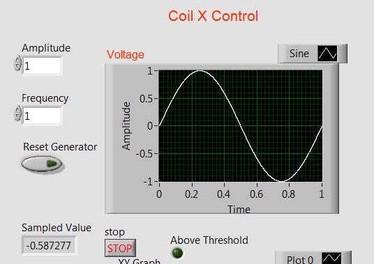
Is it possible to view the evolution of this signal in time... I mean that the "time window" on "Voltage" graph should move forward (Fig. 2).
I tried to use XY graph rather applaying (Figure 1, bottom of th), the iteration count in the loop 'While' for 'Time '.
but received an error message: "you have connected 2 terminals of different types.
What could be a solution (of course if I want it is feasible)
Thanks in advance
Pavel
Fig. 1
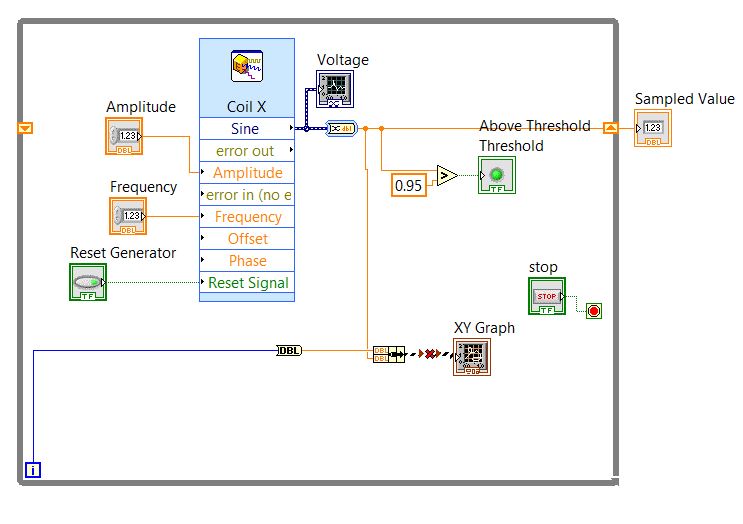
Fig. 2
Hi Pavel,
you don't 'manage' the history of a graphics buffer, you pay at the time of publishing. At runtime, it is fixed!
There is no difference between the periodic signals and not periodicals: you measure with a certain frequency of sampling and you decide Samper how useful are stored in the buffer. Point.
When you want to have a variable buffer (or: variable x scale) you must buffer on your own and use a graphic instead. So we're back to your original question: context-sensitive help will show you the data types expected for graphics, when you hover over their terminals!
Tags: NI Software
Similar Questions
-
Satellite A200 - 19L with WinXP OS - key Fn Visual control
Hi all
I have Toshiba Satellite A200 - 19L with OS WinXP (I found all drivers), but have a little problem with it:
With previous (event with this under Win VISTA) Toshiba laptops when I was doing operations with a combination of Fn keys (for example Fn + F5 - for then between the LCD screen and an external display or a projector) I could see a few icons on the screen (for the example above, a series of 3 icons representing the LCD displays only the LCD + external display) External display only; the same was hapenning when you use Fn + F6 or F7 - brightness - I saw the brightness icon and a cursor moving upwards or downwards according to the used key combination).
Now, with the XP drivers on my laptop, I have absolutely to the specific features of the Fn key combinations but HAVE a no. VISUAL CONTROL of them.
Does anyone know HOW can I restore on the computer?
Thank you guys!
I have the same problem. It worked before, until
probably a windows update has been mess up with the function FN + F5.
I tried to update the driver for the graphics card from NVIDIA. Who knows...
I try so many things, but it does not work.When I press FN + F5, I have only the choice with the icon of the LCD screen. Until I'm OCR a and OCR + LCD screen (they disappeared).
I wrote to TOSHIBA, but no response. I read on many forums that much laptop Toshiba you have this problem.Could someone help us?
Thank you -
Frequency of an analogue signal measurement and noise reduction
Hello everyone.
I'm reading a flow rate sensor that generates output signal square whose frequency has a linear relationship with the flow rate and varies from 37 to 550 Hz. My hardware does not support playback of the frequency, so I have to calculate. What I ended up doing was reading signal every 1 millisecond (1000 Hz), taking two samples spread and store the value of the signal and the time during which it was read. Every 400 milliseconds, I loop over the data and know how many cycles have taken place and the time between the first and the last cycle, divide the number of cycles at this time here.
Here's a graph of the signal.

I never use software loops timed then performing operations of data acquisition as a general rule. He's many trendy on negative issues. And as you mentioned that you cannot run a timed loop faster than 1 kHz. You should go to the Help menu in the toolbar, then select search examples. Then you look up "continuous acq. It is best to leave all the details of the calendar to the data acquisition unit and just retrieve data from the buffer of data acquisition, then it is needed. I have your case I would recommend a sample equal to 6 kHz freq. That's more than 10 times your highest frequency. You can always update your data at intervals to 400msec. Your signal also looks good. I can't have a lot of noise in your signal. If my guess is that your software is not optimal. You should not get 120 Hz, so there is no flow. If you post we can take a look.
-
How can I change a variant of time 2D a 2D string?
Hi, I'm new to LabVIEW. Can someone help me with this issue?
How can I change a variant of time 2D a 2D string?
Please see attached.
mrgudwrnch
You have variants or a 2D array. You need to break out of the loop is a table 1 d of the stamps. To convert a timestamp into a string, you can use the Format in the string or the string of Format of Date/timefunction. Writing worksheet function has an entry in the 1 d array, so you can use it instead of the 2D to entry.
-
splitting of a signal in the time domain
Please can someone help me with how can I split a signal at different time scales.
What I try to achieve is to decompose a signal in time.
UXE
Look at the subset or remove table from the table. If the data is a form of wave, extracted from the table data type, select the row and build a new waveform of the subarray.
Lyn
-
The monitor loses signal after some time
During the installation of windows vista, the monitor would lose the signal after some time (the screen turns black and does not) while the computer is still on. I am currently using ATI radeon hd 5750 and I tried to connect two monitors to the video card and it wouldn't work (both monitors loser of the signal)
Hi PaulYea,
1. what type of Installation are you trying? It's an upgrade or clean Installtion?
2. what happens when you connect to the system now?
If you attempt an upgrade installation, then try the update the video card drivers and check:
Update drivers: recommended links
http://Windows.Microsoft.com/en-us/Windows-Vista/update-drivers-recommended-links
You can also check out the link to the manufacturer to download the drivers:
You can also try running Upgrade Advisor and start the upgrade installation
Check out the link:
http://Windows.Microsoft.com/en-us/Windows/downloads/Upgrade-Advisor
Note: This also applies to Vista.
For more information, see the link:
Solving Windows installation problems
http://Windows.Microsoft.com/en-us/Windows-Vista/troubleshoot-Windows-installation-problems
Hope this information is useful.
-
Control chart and mixed signals tab crashed for LabView 2009
I find a serious problem by using the chart of mixed signals with tab control. Two examples and detailed drscription are attached. In TestMix.vi there is mixed, graphics and additional code to display the data. Normal execution of the program. I add the tab control and move the graph mixed signal in Page 2 (see TestMix2.vi). After registration as TestMix2, close the vi and oppening is façade of LabView frozen after touching on page 2 of the tab control.
Does anyone have the solution for this case?
Best regards!
In his stavljanjem digitalnog dijela na kraj grafa sam otkrio kao slucajnost, ali only Monte puku is tako I dolazi zaobilaznog rijesenja.
Kada dobije informaciju od kolega bi bug mogao biti rijesen obavijestiti cu spomenuti kada go! Moze biti u Drugom.mp3 od nadolazecih patchova ili u sljedecoj verziji LabView eventualno - a.
Srdacan pozdrav
Franjo Tonkovic
-
PCI6120-acquire an analogue signal on each edge of a digital signal
Hello
I have the card PCI-6120 and Labview 7.1.
I have a digital signal of the encoder. Am interested in buying an analog voltage on each rising edge of the digital signal. In addition, I have another digital signal (index) between which I wish to make the acquisition.
I tried several options. But I can't get on the digital dashboard via the hardware. Please help urgently. Alternative, I migrated to the acquisitions acquisition high speed analog and two digital channels and deteting change in software programming and then find the analog voltage. Which is heavy and inefficient.
Kindly guide correct programming technique.
Concerning
Marie-Hélène
Hi, Maud.
Thanks for the update and I hope that your well today.
Sorry for the delay but it was the Easter holidays!
Thank you for your congratulations.
I put your sampling frequency at the maximum rate of the clock source (encoder). The DAQmx driver uses the sampling frequency (and the number of samples per channel) information to perform various calculations and set sizes for the buffer.
If you set it too high, nothing will happen-guests still just on each edge of the unit receive. If you set it too low, your stamp could be too small and you may lose data.
Hope this helps,
-
SMU-6556 - how to control the rise in digital lines (hsdio) time
Hello
Is it possible to control the rise in digital lines SMU-6556 time?
Even in a low frequency 10 kHz signal rise time is 2ns.
TKS,
Hello engfpe,
The SMU-6556 is a 50 Ohm system, which means that the output is source series finished to be 50 Ohms and all our cables and accessories are 50 Ohms. With this configuration, regardless of the flow of data, you should have a clean edge up or down, regardless of the data rate. The quality of the production (edge up or down) on your device is related to the adaptation of impedance of your cables.
The SMU-6556 cannot adjust the speed of scanning by itself. However, you can insert simple passive components to do it for you. I have attached below the images. The first is a diagram showing a way to slow down the edge. The second is the a waveform simulation showing the rate of original edge before it slows down and the edge of idle. This simulation is not the SMU-6556 but rather a generic digital output for concept. In the schema that R1 is set on 34 Ohms because U1.8 has the 16 additional Ohms on the inside. TL1 is the output of 50 ohms simulating the cable on the SMU-6556. R2, R3, and C1 are components, you can insert after the SMU-6556 twist before moving your device/cable. In this configuration from cable to your device is TL2 which is also 50 ohm, but it could be another impedance in which case you would change R3 to match.
You can see in the attached images, you can slow down significantly the edge with this configuration by altering the C1. I hope this helps.
-
Two Apple TV - remote controls works with both at the same time
Just bought the Apple TV 4, this means that I moved my old version 3 Apple TV in the room, when I use a distance the two Apple TV now respond. How can I connect the remote control for the Apple TV right, to keep them from harm?
Try this:
Désapparier money ATV3 the remote control by pressing menu and left for 6 seconds.
Block the front ATV3 and remote peer with the ATV4 the silver medal by pressing menu and right for 5 seconds.
Block the front ATV and press menu and the central selection button for 5 seconds
Unlock the ATV4 and check that it does not meet the silver remote.
Block the ATV4 and unblock the pair by pressing menu and right for 5 seconds and ATV3.
Check the ATV3 now responds.
Remove the block of the ATV4.
A beer...
-
Control two E3631A outputs at the same time with the values of voltage defined in excel
Hello
It's my first time using LabView and I want to control remote E3631A power using the instrument driver. I downloaded the driver from this site http://sine.ni.com/apps/utf8/niid_web_display.download_page?p_id_guid=0475216F9FCA5335E0440003BA7CCD...
Basically, there are two different files excel for the two output channels (+ 6V and + 25V). I'm trying to use the two output channels to review the voltage defined in excel files every second. I am able to extract data from excel, but my problem now is that I'm not sure on how to control both channels simultaneously. Could someone please help me solve this problem?
Thank you.
Just use the VI of output configure in drivers to set each supply individually.
-
How to control the two analog outputs at a time
I'm new to LabVIEW and have some problems in DAQmx with control outputs analog multiple.
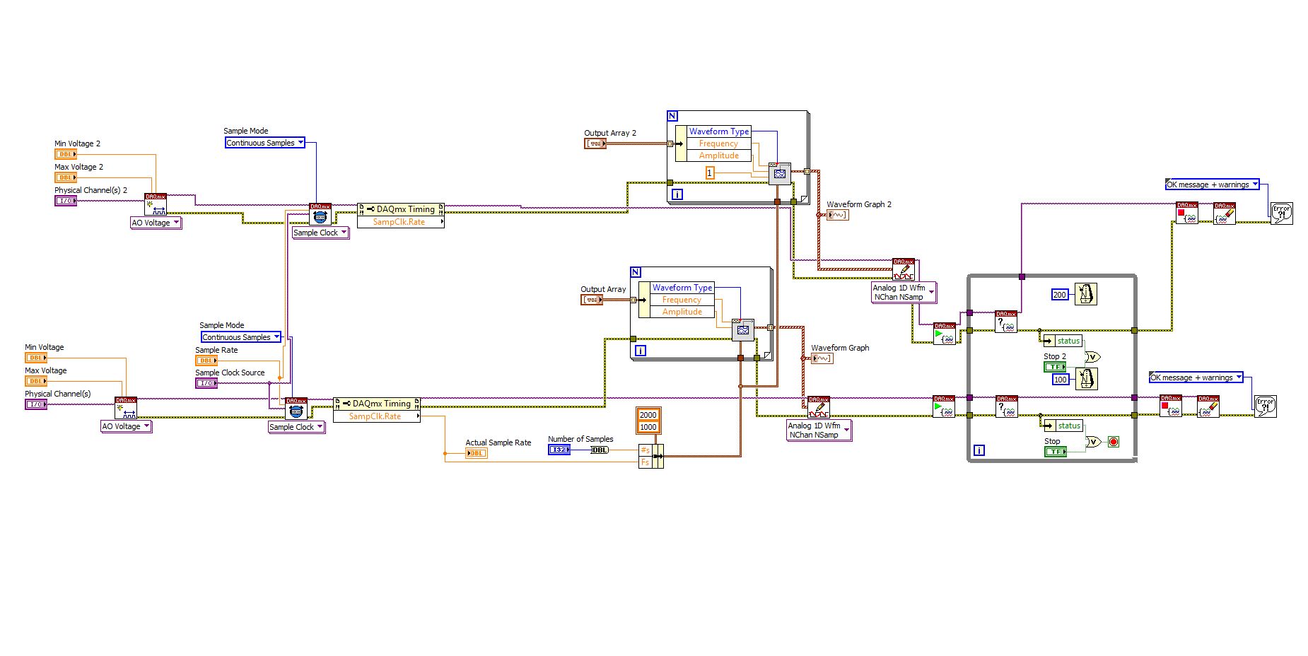
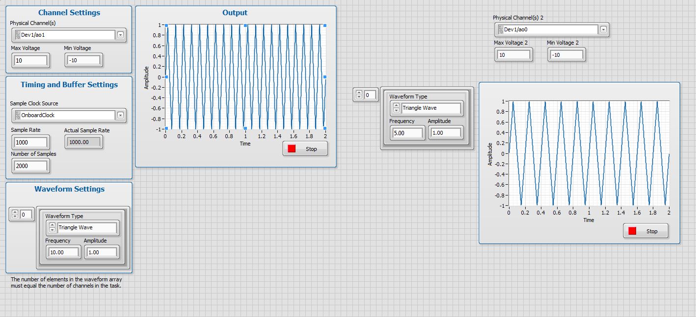
I want to set up a platform using BNC-2110 and PCIe6363 to control two rotating mirrors. The problem that I can only give an output (AO0 or AO1) at a time and I really have no idea how revise my LabVIEW diagram to control two outputs at the same time I met. I tried to change the outputs and it keeps a mirror turning instead of the old. Could someone help me with my problem and I would really appreciate. This is my blocked diagram and front.
Hi zrmaker,
As mentioned by RavensFan, you should not create 2 analog outputs different tasks if you use AO0 AO1. To your façade > physical control or the channels > select the drop-down list of the control channel physical (s) > Browse > hold down the CTRL + select the AO0 and AO1 > Select OK. Once this is done, you will see that your control or the physical channels has the following input values: "Dev1 / ao0:1" which means that you will access to AO0 AO1.
In regards to writing DAQmx, simply select Analog > multiple channels > samples multiple > 1 waveform (you should get the following: 1 d Analog Waveform NChan NSamp). Once done, you can just use table build to combine 2 different waveforms and plug in this table to DAQmx writing output. The first index will be the output for AO0 value and the other will be for AO1.
You can check this link on how to read or write from several channels: http://digital.ni.com/public.nsf/allkb/0C1ADEF06A54AB2D862575040066FD51
Additional reference:
http://www.NI.com/white-paper/2835/en/Hope that helps.
Warm greetings,
Lennard.C
-
How to get a signal triggered by TIMER (under Board user) using GetUserEvent() event
Hello
I want to use GetUserEvent() inside a loop for the TIMER event, rather than use the calllback RunUserInterface() and TIMER to vote.
but it seems that GetUserEvent() can not get the TIMER event. Is there something I should note before using GetUserEvent()?
I use a button (PANEL_Add) switch TIMER ON / OFF, the time interval is 1 second and TIMER is initially DISABLED.
PANEL_LED indicates the State of the TIMER POWER indicator.
PANEL_LED did turn after I click on the command button, but the value of the counter has not changed anyway when the TIMER is activated.
Thank you for answering ~.
Here is my code
==================================================================
int main (int argc, char * argv [])
{
error int = 0;
int done = FALSE;
int eventPanel;
int eventCtrl;
int panelHandle;
unsigned int Count = 0;
flag of the int = 0;
/ * initialize and load resources * /.
If (InitCVIRTE (0, argv, 0) == 0)
Returns - 1;
If ((panelHandle = LoadPanel (0, "Timer.uir", PANNEAU)))<=>
Returns - 1;
/ * display of the control panel and run the user interface * /.
DisplayPanel (panelHandle);
While that (is FALSE) {}
GetUserEvent (1, & eventPanel, & eventCtrl);Switch (eventCtrl) {}
case PANEL_Add: flag = (flag == TRUE)? FALSE: TRUE;
SetCtrlAttribute (panelHandle, PANEL_TIMER, ATTR_ENABLED, flag);
SetCtrlVal (panelHandle, PANEL_LED, flag);
break;case PANEL_TIMER: SetCtrlVal (panelHandle, PANEL_Counter, Count ++);
If (Count > 19)
Count = 0;
break;
}
}/ * Cleanup * /.
DiscardPanel (panelHandle);
CloseCVIRTE ();
return 0;
}and here's the .h file
==================================
#include
#ifdef __cplusplus
extern "C" {}
#endif#define PANEL 1
#define PANEL_Counter 2
#define PANEL_Add 3
#define PANEL_LED 4
#define PANEL_TIMER 5#ifdef __cplusplus
}
#endifHello
According to aid GetUserEvent Gets the next validation event or an event defined by the programmer of the GetUserEvent queue. A validation event occurs when the user changes the State of a hot water or validate controls or selects a menu item.
Place the events defined by the programmer in the GetUserEvent queue by calling QueueUserEvent.
Because the timer does not generate a validation event, you must call QueueUserEvent; to do this, you will need to use the TimerCallback function that you don't like... I see no other way than to use the timer callback function
-
signal split several times on target RT
Hello
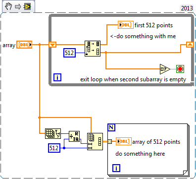
I have a signal composed of 50,000 items on my RT cRIO and I want to split the signal into 97 signals of 512 items each. Is there a way to apply this using blocks of Labview? So far, I've implemented using a MathScript and a loop, but the program is very slow work because of this.
THX,
Valentina
Here is an excerpt with two ways to do this - assuming you want to use on your 97 subdashboards one after the other and not them erupt in 97 different threads on the same scheme, which would be cumbersome to say the least!
The first uses Split 1 table D a while loop with a shift register and an empty array? in the range of comparison to determine when leaving the loop. The other uses the table to reshape and a loop For with automatic indexing enabled - I am no expert on this but I think that the compiler may be able to paralellise that better, if performance is a problem.
Note that if your input array is not an exact multiple of 512 points then the first solution will give you a short range at the end while the other is will ignore the last<512 points="" -="" you'll="" need="" to="" modify="" whichever="" one="" you="" use="" if="" that="" isn't="" what="" you="">
-
problem while conspiring waveform of the signal in real-time
Dear Sir
I use LabVIEW8.2 and USB1208FS for data acquisition. I have configured hardware with LabVIEW and data in real time using the Universal Library VI AInScBg.vi. When I draw my signal on the waveform (amplitude vs. frequency) then on axis x frequency ranges from 0 ~ 0.49 hz. I have change the sampling rate of 1000 Hz to 4000 Hz, but on the x-axis without frequency change occurs and it is set at 0.49 hz. Can you please guide me how can I get the frequency of my own interest on the x-axis.
I enclose you daughter of LabVIEW for reference.
Kind regards
Muhammad Irfan
Student
UTP Malaysia
0060149087570
Simply change the text label of the x-axis of frequency does not automatically the correct calculation. You do not pass in the sample information in the service spectrum, so you get no frequency information. You can see the strain on the entry point. The function expects a data type of waveform as input. Without it, the dt will default to 1. Then, use the function create a waveform and add information from dt to it as well as your table of Y.
Maybe you are looking for
-
Flashing LEDS with digital control
Hello I want to do a simple program that goes like this. I have 2 digital controls and 2 comparisons. 1 digital will compare if the number if there is less than 50. Second comparison if it is longer than 50. If less than 50, according to this number
-
Incorrect password for computer Sony laptop XP
Yes was lettin my daughter use my old laptop sonypcg-frv37 got in a fight now I can't get the password right back to what to do? * original title - me professional xp lockout on my viao old *.
-
Need to cut a few passport-sized photos.
Remember - this is a public forum so never post private information such as numbers of mail or telephone! Ideas: have looked for size and reduce aid with no result. You have problems with programs Error messages Recent changes to your computer What y
-
I had problems last week with media player in Vista Business, so on the advice of here, I have improved. Everything went smoothly, relativley until this morning. Media and Expressions work just fine. However, I backup images that I download in RAW a
-
installed Office 365 on windows 7
I installed Office 365 on my Windows 7 computer Now I opened Excel, create a new workbook and I do what I've always done, nothing more and nothing less. After changes to the workbook and other tasks, I close and save the workbook in my documents dire