Voltage divider
I created a four, three loading voltage divider resistance in multisim. I did all the calculations for the circuit. When in simulate mode the values of voltage and current that are returned by the software do not match my calculations. It looks like multisim may not resolve to the correct values on this type of circuit. Is this an accurate statement or I don't expect too much of the software?
Multisim 11.0.1
I used dynamic probes under the simulation menu. Thank you very much for the help!
Tags: NI Software
Similar Questions
-
USB-6210 voltage divider Calibration questions
I'm trying to calibrate 14 tensions that I read from a voltage divider in 14 channels of a device USB-6210. Attached is an Excel spreadsheet of data I'm trying to understand. On the bottom of the sheet, I applied the same voltage to all channels and draw the raw tension for all channels and the differences between the expected voltage and voltage of raw. I find that these differences are not constant but linear I do not understand. I then use the basic linear function to find the factors in the top of the worksheet. Therefore, in the upper part, I read the input voltage by using a probe high voltage and voltage of Labview which has been adapted by the linear function of base in the background. Most of the multiplying factors are ~ 1000 as expected, but the tensions for the last 4 channels are significantly different and are not linear for the last two channels. I mounted the two worst voltage channels with polynomial which is ok but not make any sense. Does make sense to anyone. I'm using Labview 9.0.1 and Windows 7. I ran Diagnostic Utility for the acquisition of data on the device and it passed all tests. I looked into the issue of ghosting, but the criteria seem not valid here because of tension in the neighbouring country of the channels is small. I also enclose the VI that supports voltages raw to show how these functions are used. According to me, the results are stable and precise, but I can't explain the above mentioned discrepancies.
The problem was solved by changing the sampling frequency in the DAQ assistant. I think the default frequency is 1 kHz and I had given up to 750 Hz. By lowering the frequency 150 Hz, the capacitor is allowed time to discharge so that no ghost image occurs. In summary, the question always was ghosting and solve the I: question
-Removed in the wizard DAQ, channels that have been disconnected and therefore not used.
-Change the wiring to the DAQ assistant by sending the low voltage in channel 1 and the second lowest voltage on channel 2, etc.
-Change the sampling frequency of 1 kHz to 150 Hz to let the capacitors discharge time.
-
How do you install resistances for channels 8-31 voltage divider in scb - 68?
I use an analog output card, NI 6723 and I need to ease the tensions between the connector of channel 8-31. Is it possible to install to these channels voltage divider resistors in a block of connection scb-68? The manual I have shows, it is possible, but it doesn't seem to be enough positions in the box for 24 pairs of resistors.
I found a newer version of the online manual. It seems that 2 channels AO can be conditioned in this way. Thank you.
-
A voltage divider will be enough to read a 28V pulse in NOR-6251 digital input ports?
Hi all
I am a scientist life sciences that attempts to read a 28V 4.2mA pulse signal sent from my operative box animals in my NOR-6251.
Sounds like a voltage divider should do the job. But I would be aware of anything else that my card OR not to burn? And should I be concerned about the current entry in the map OR?
Thanks for your help!
Hello
Research on page 7 and 8 of the Datasheet of NOR-6251 , it shows that the maximum voltage is 5.25V, so use a voltage divider to make 28V up to 5V and you should have no problem providing you can guarantee your 28V source will always be to 28V or less and your resistances are fairly accurate. Under no circumstances should provide you more 5.25V to the digital input.
The only concern you have on current is that the resistance divider is not affected by the impedance of the digital input which is little likely (datasheet says max 250uA), so if you use resistors around the range of 5 to 50 k, you should be fine. Also, be sure your part of wiring resistance as if she had the wrong way, you will have a great chance to break the map!
I hope this helps!
-
out of meter can be fed in a simple voltage divider?
I managed to install this labview program: http://www.ni.com/white-paper/2991/en
and I know it works because I see a pulse when connecting to the Terminal counter on the BNC-2110 block train on the oscilloscope.
I use a DAQ 6259 pci-e card.
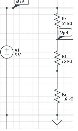
I noticed the amplitude of the signal is about 5V, but I need it to be approximately 3V. Then I fed the pulse train in a circuit voltage divider simple that looks like:
Above v1 is actually the PWM signal from the counter of the BNC-2110 block Terminal. However, when I measure the amplitude on the oscilloscope, it's always as 5V (or perhaps 4.9).
Am I missing something big here?
Hi invasion2121,
There should be no problem with dividing the output voltage of your meter. Your photo has been cut off slightly in head - are survey you the voltage falls through R7 where you see 4, 9-5 V? That means the voltage on the rest of the circuit looks like? The output of the counter provide more than 5 V output to the Earth, so if A7 is down more than that, then your voltage on R1 and R2 should be almost 0.
What is the impedance of your reach? This can have an effect on your measure, but not as you describe.
Kind regards
-
1V - 5v linear output using power supply 5v, voltage divider, and variable resistance
How can I get 1v - 5v output linear using power supply 5v, voltage divider, and variable resistance?
Have the you wired as an attachment? Using my schema, you can calculate the current flowing through the pot based on the fall of the tension in the pot
4V / 10Kohm = 0.0004
Kirchhoff's current law, we know that the same current flows through the circuit so now we can calculate the leg below the wall, based on the current and the fall of desired voltage across the resistance
1V / 0.0004 A = 2.5 K Ohm
My scheme maintains the current flowing through the circuit of constant, so the voltage divider must never change. Assuming a linear pot, you will get a swing of such linear voltage as measured at the wiper. If you wired the pot, a different way, then more then likely, you change the total resistance of 5V ground that would have the common effect that would effect the tensions.
-
MyDAQ handeling voltage 10 v If we have the tension goes down
Hello! I use a MyDAQ and I need to get a signal from a different device. Here's my question. Looks like the MyDAQ can manage 10 +-volts, but can it be damaged if I give him a 24V signal and use a lot of resistance to lower blood?
I show a short way of how I think about the attachmentfile.
Thank you
Hi Kristage, you can design a voltage divider to reduce from 24 v to 10 v range. Always remember that when designing, select resistances so that 0 to 24v cards to-10 v to 10 v for better accuracy on the beach of the full scale of the device. Best regards Deepu Jacob
-
SCXI 1338 - input voltage range
Hi all
I use SCXI-1338 blocks in modules SCXI-1125. Currently channels measure currents in the 4milliamps range at 20 Ma.
I'll be able to measure signals VOLATGE by connecting to the SCXI-1338 module, and what is the range of acceptable voltage AC or DC? And also should I do everything
changes in the SCXI-1338 module block in order to measure the voltage signals? I want to measure 20V DC signal controlled by a PLC.
Thanking you.
Well, what it really comes down to the Ohm's law in the end. V/r = I, you'll 20V/250Ohms = ~ 80mA which is well above the limit of the 1125 and the 1338. I recommend you either go with the voltage attenuator 1327 or you could possibly do external cables to a voltage divider. If you place a resistance of 1kOhm serial then your V/R = I equation turns into 20V/1250 Ohms = ~ 16mA max. To find your tension, you must create a custom scale to account for this new resistance. However, given that most of the resistance will be a mistake, it would be better if you measured the resistance of the circuit using a multimeter or an equivalent for an estimate more precise of the real resistance.
In the end, the 1327 is going to be a cleaner solution, but you can also go the road of voltage divider if this does not work for you.
Lars
-
NEITHER USB 6008 voltage offset using CSR and measurement of diff.
Hi all
I am currently trying the NI USB 6008 housing and I'm getting problems when reading voltage analog using CSR or differential.
So basically, what I want to measure is a PWM signal (0 to 12V), which is divided by a divisor of tension (by two). But instead of measured 0V and 6V
I am in a position a constant 0.8V and approximately 3V.
On the side of digital data acquisition, I give you on impulses for the SSR... and it works fine.
I connect it that way: http://digital.ni.com/public.nsf/allkb/95CC0CB11D7DF3D18625712E000C4ABD?OpenDocument
Would apreciate any help
Best regards
EDIT: Attached graphics acquired are
What is the impedance of your voltage divider? The input of the USB-6008 impedance is not very high. If the impedance of the partition is large, it could cause the effect you see.
Lynn
-
Measurement of the current rail voltage > 10V
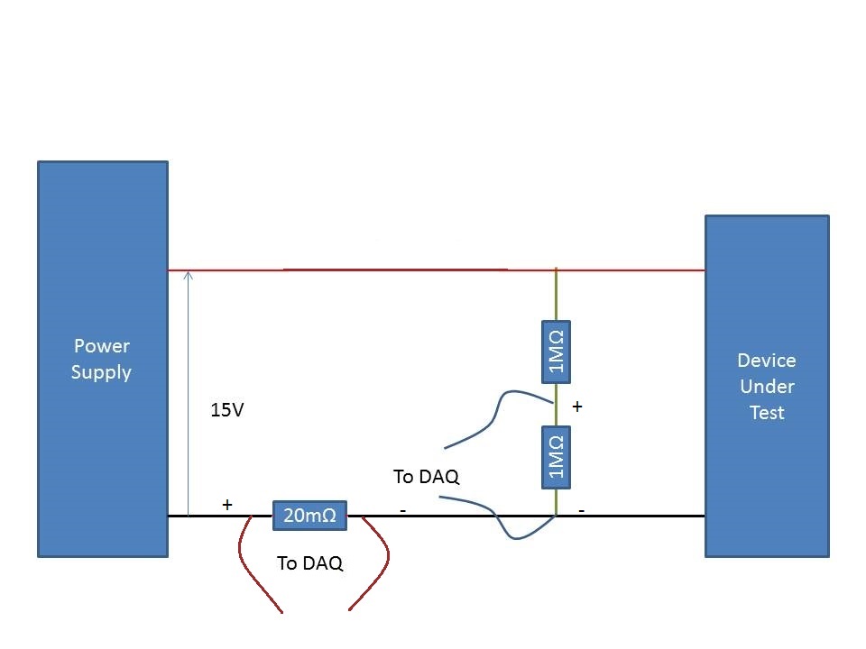
Who am I to measure the current and voltage on a 15V supply rail. (Here's a copy of my circuit attatched) I use an acquisition of data USB-6225 and Lab View,
I have my camera to test connected to a power source. I connected two differential channels to the acquisition of data, one for the current and the other for the voltage.
I understand that data acquisition is unable to manage more than 10V so I use a voltage halfway through the voltage divider. When I run the action, the indicated current is incorrect. It shows the 10A when it should be about 500 my.
When I reduce the tension on the power supply 10V, it everything works fine, so I think that its got something to do with the limit of 10V.
Please can you advise how I can connect that places correctly?
Do it this way.
-
I have already built a 8-channel 10:1 voltage divider using 1% resistors. My problem is there is a lot of AC noise on the signal of the DC and tensions do not match my Fluke DVM who is seated nearby.
A little more info... Only channels 1 and 2 have signal going to them. CH1, (a0), is connected to a battery of 9 volts and ch2, (a1), is a set of power-related variable bench for 17Vcc.
The digital Voltmeter is rock steady, however, the LabVIEW indicators show which I suppose is a product of AC noise.
Any help would be appreciated

Thank you very much
-Matt
-
floating voltage solution 6008
Hi there are many questions concerning the entry volatages analog of usb 6008 floating 1.4 volts which is logical because of the electronics.
How people come up with to get around this?
My circuit is shown in the attached Jpeg format. I effectivly have a voltage divider from 0 to 200 volts up to 0 - 5V using values of resistance of 470 K and 12 K. A solution would be to abandon the resistance values down, so he pulls the bottom of the daq so resistor network. I would like to avoid droping the values down too as I want to minimize the current drawn by the circuit. I see currently on 100mV on my entry.
It would be good to have some solutions in the following areas:
(A) electronic hardware
(B) equipment OR IE what DAQ would be better
Solution software C) (obviously there are limits, but there could be a combined hardware/software solution)
An output buffer amplifier low impedance is probably the solution the most straighforward and costs quite a bit less than buying another DAQ hardware. I haven't checked all the other devices, but I don't think that the USB-600 x devices have this strange input circuit.
Since you know the circuit of your part, it should be possible to calculate the effect and compensate for in the software. If you try this, run the calibration checks. "On page 18 (last paragraph) of the USB-6008-9 User Guide he mentions the shooting to 1.4 V and adds input circuit:"
This behavior is normal and does not affect the measure when a signal is connected. "It can be concluded that devices of are internal compensation under the assumption that there is no source impedance. If they do, it will complicate any effort to compensate external source impedance.
Lynn
-
Hello
I use PCI 6025E to control load Bank and to measure the voltage, current and frequency of a generator.
Current and the frequency is not a problem, voltage is toublesome.
As on test bench already there are few PCI cards and large number of sensors, I don't want to add NI 9205 or any other additional maps and the size of the area (other people are also working there).The problem with blood pressure is three two generators spend 400 rpm to 1600 rpm is. some 15 to 55 Hz.
I got two solutions for this:
1, put a step down transformer (230 Vac / 5 Vac) and then measure the voltage. But I have to deal with magnetic saturation with commercially available processor during the test to something like 15 Hz. I don't want to take the pain to built my own transformer.
2, using high precision voltage divider. The problem is that what should be the galvanic insulation? Insulation transformer, but still low frequency problem.
Where could someone suggest me because there is a bit of confusion in my head.
Thank you.
If you have a sinusoidal generator (15 Hz migth be hard for the soundcard
 ) you can do a calibration of your transformer.
(If only the amplitude of the voltage is of interest, use a DMM isolated as a reference and run your generators)
Or you buy an insulation voltage amplifier. (weidmueller, phoenix, wago,...)
-
Geographical address on the device voltage map PXI express
Members of the forum good day!
I am designing a PXI express card that must be inserted into a NI PXI express chassis. I read the documentation and specifications PXI, PXI express, of the cPCIexpress, but it seems that I'm not able to find any specification of voltage level for the BC (pins geographical address) that are present in the J4 connector. I need to know at least the input voltage prior to high level connect them to the FPGA that is on board. I'd like to connect a 12 Volt signal directly to a Bank of the FPGA 1.8V. Yes, I know, I can always use a (made with resistors) voltage divider in front of entrances FPGA, but better know the spcifications before conception to design something wrongly, in my view.
Can someone give a tip?
Thank you very much
Emanuele
A more precise answer to your question: the GA pins are floating or tied to GND. You are expected to pull up on your Board to what voltage is suitable for your device.
-Robert
-
Why voltage does not change when I put a resistor in parallel?
Hi all
I have observed something that seems quite strange and I do not understand. I'm under Multisim 10.1.1.
I have a sinusoidal voltage source that is diode full-wave rectified by a RC parallel network for the purpose of obtaining 120VDC, who has everything works beautifully. I am in a position the voltage with a voltmeter. Crazy is when I put a resistor in parallel with this output 120VDC, voltage drastically changes. For example, when I put a resistance of 1kohm in parallel with the release of 120VDC, the voltmeter reading falls drastically to 0.835V.
Of course if I perform this test with a simple DC 120V source, the voltmeter reading remains stable at 120VDC.
Does anyone have AN idea why this is happening? I am full of ideas. Thanks a lot for all the help in advance!
Sorry for the frequent posts, I was not thinking clearly yesterday night when I posted this question. Voltage divider simple problem. Sorry again!
Maybe you are looking for
-
Satellite L670-12J - Chicony camera does not not after installing Win 10
Hi I have just upgraded to Windows 10 on my L670-12J and the camera not working anymore. I tried to search for a driver Win 10, but I have found none.Also some of the function keys don't work anymore and of course the tab that opens at the top of the
-
Microsoft Visual C++ Runtime Library: Buffer overflow
Hi, recently I met problems with call of duty 1 when executing it. Whenever I double click CoDSP.exe this error message appears: "Microsoft Visual C++ Runtime LibraryBuffer overrun detected!Program:... .gram Files\Activision\Call of duty 1\CoDSP.exeA
-
method accewwing from another thread causes some 'bad object type' error with c# VS2008
I'm snapping a picture to a main Viewer, draw a rectangle around an alignment and extract the part of the image to a different viewer for further processing. I tried everthing and all was good until I started to build a Wizard for the operator throug
-
Hu_RSAKeySet RSA public key encryption
I have a public key and I'm trying to encrypt data with it. This is my code: sb_GlobalCtx globalContext; hu_GlobalCtxCreateDefault(&globalContext); hu_RegisterSbg56RSA(globalContext); hu_RegisterSbg56(globalContext); hu_RegisterSystemSeed(globalCont
-
installed slow start with driver for HP Color LaserJet CM2320nf MFP
I have Windows 7 pro 64-bit installed. After that I installed the latest driver for HP Color LaserJet CM2320nf MFP, my network is not initialize 2 to 5 minuets and the PC won't start any programs until it does. The printer works very well after start