Vst 5645r PXI gain / attenuation calibration chain RX TX
Hello
I work with PXI vst 5645r. I did some research using the RF output of the transmitter connected with the receiver RF input.
In my application, it is important to know the equivalent mitigation and win I get (output of the DAC) generation up to the acquisition (input of the ADC) (loop gain).
I looked at http://zone.ni.com/reference/en-XX/help/373680C-01/vstdevices/5645_analog_input/ and http://zone.ni.com/reference/en-XX/help/373680C-01/vstdevices/5645_analog_output/ in order to better understand how to build the structure of my channels.
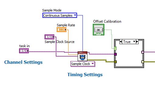
Whole, I looked in the drawing in labview how these parameters are controlled and value (example VST streaming (host)). I found only the configuration of gain for the transmitter in the 'LO_cal' block but I don't see no calculations for the various mitigations of transmitter. I have to check these datas for the transmitter.
How are managed and put all these settings in the transmitter and the receiver normally?
I guess that the receiver channel attenuates the signal in order to use the dynamic maximum range od a/d converters and use good power from receiver... calibration changes the values of gain/attenuation in the receiver string whenever I use a different gain (peak power dbm) of the issuer?
Thanks in advance
Best regards
Giuseppe
The reference level is a 'guide' for the driver VST set the attenuators and win as well as the range of the ADC/DAC are used at best.
Depending on the frequency that you and the chosen reference level, the VST pilot will focus on the best combination of the mitigations
and win to get the Signal arriving at the ADC to use his full range:
You can see the calculations in this niRFRIO Group A Config 1.0.0 Shared Private.lvlib elect RF calibrated Gain.vi
This Gain is 'Gain of frequency step-down converter' that summarize the entire path of Rf In.
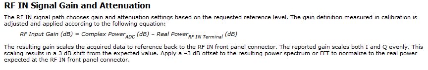
So practicall frequencies/Upconverter Gain step-down converter is the total analog gain that is put on the signal just before and after the ADC/DAC.
This is done in the niRFRIO Group A Config 1.0.0 Shared Private.lvlibelect RF calibrated in Gain.vi.
The discovery to Gain Index scan all possible power levels for this frequency and get the level closest to the chosen reference level.
Whith this information, he knows what attenuators and win it must reach the power to get at its best at the ADC (input gain settings)
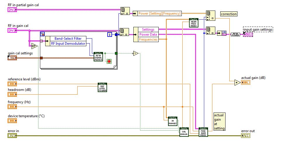
So to calculate the loop gain, you must define a level of refeerence fix so that all mitigations and gain in the two paths of remain fixed, test it with a calibrated CW and then use this configuration for your DUT.
When you read the QI of the VST (retrieve a single record) this information is passed to the function, so it can calculate the values of CDA and calibrated to their actual value on the RF In:
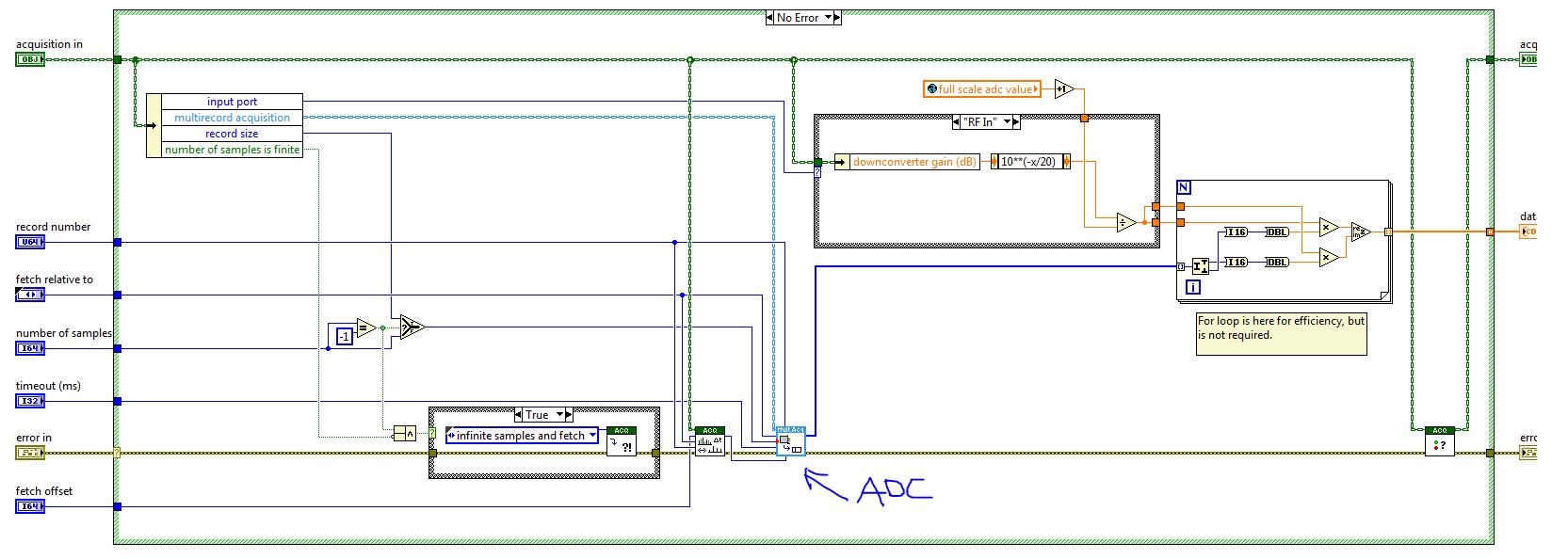
If you calculate the gain of loop inside the FPGA, then he must send the information of step-down converter frequency/upconverter gain between the host and the FPGA. You can then use this information to calculate the loop gain.
Best wishes
Tags: NI Hardware
Similar Questions
-
Time-out error when you try to calibrate a PXI-6552 using Calibration Executive.
I make a mistake I never saw elsewhere trying to calibrate a PXI-6552 using Calibration Executive. We have been calibrating these cards for 3 years and never had a problem. The error I get has to do with the HP 3458 A DMM taking a reading.
1074126845 error occurred at IviDMM Read.vi in audit generation step voltage
The possible reasons: maximum time state of the driver (Hex 0xBFFA2003) exceeded before the operation is complete.
The primary error: (Hex 0xBFFF0015) timeout expired before the operation is complete.As soon as Cal Exec implements the PXI-6552 module then will take a reading of the 3458A what an SRQ message on the 3458A, then the error message above appears in Cal Exec. I tried to reinstall the drivers OR DMM. The voltage on the meter screen is good for the first stage (5.5 volts DC), but it times out and gives me the error as indicated.
Nevermind, I got the latest drivers and install and everything works fine now.
-
withdrawal of a th ack PXI module
I need to send some PXI modules for calibration but am unable to get off the PXI rack PXI modules and rather
to force these and potentially break.
I googled for how to remove the PXI modules, but unfortunately, I can only find online information about how to install the PXI modules.
Can someone send me a link to any documentation OR how to uninstall the PXI modules from a PXI square?
Thank you
Too bad...
I just found out that National Instruments skillfully hid a mounting screws out of sight under the level of edjector
and then took the trouble of this document anywhere on how to remove a PXI module in order to improve the
customer experience.
...
-
Read Calibration expiration with Labview
Hello everyone,
I found a way to read the configuration of my PXI-1044. I would read the section external calibration of the Calibration tab in MAX for my PXI-5114 and PXI-4065 (last calibrated and recommended the next Dates of calibration) using Labview to read. The preferred format, I'm looking is similar to the configuration of my PXI-1044 which retrieves data in a format delimited by tabs. Thanks in advance for any information that can throw this forum on this topic.
Kind regards
Scott
Hi Dennis,
Thank you for your most recent reply.
Thanks for the vi. I tried on one of the systems and other that it could not find the Initialize.vi, I replaced with one that is the measure of e/s > System Configuration, it will do the job and data retrieval will not be a problem.
Many thanks for your efforts to help me better understand this particular function and please pass the file. I consider this closed post.
Kind regards
Scott
-
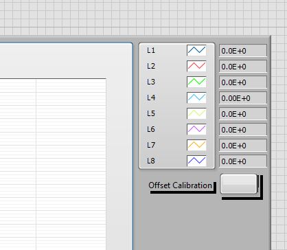
Place a button for calibration of the strain gages on the façade
Hello
I'm relatively new to LabVIEW, and I'm trying to place a button on the front of a VI that is designed to graphically view statements for voltage of several strain gauges. I tried to use the offset calibration DaqMX bridge Subvi initially, but is not the same thing as the calibration button of the strain on the device tab in MAX.
Can someone help me to do it properly? I know that's not much more difficult to just do the calibration in MAX, but my supervisor is looking for the VI to be as simple as possible for the user.
Thank you!

for a project that I use on average for gauge calibration chain
I Place a button when the press op that he finds the average of the last ten value of voltage and then I use it as V0 in the vi strain using shift register
is this great method for you?
If so I can give you examples of code -
Problem of reliability data acquisition PXI-4071
Hello
I'm having a problem of reliability using my 4071 Pxi digitizer mode.
I have a number of tests that use the SMU-6363 (usually configured for DC) analog output to provide a stimulus for our own device, which has a number of a/d converters. We use the PXI system for calibration and testing.
1. I select a voltage ranging from tensions.
2. program the PXI-6363 to drive this tension
3 TIME about 10ms to settle. Note there no discrete capacitors or resistors in the circuit. Everything is parasitic and would generally be under the nF mark and less than 10 ohms
3. configure and Initiate() acquisition of data with the PXI-4071. In general, I use a sample rate of 1000 s/s and get about 30 samples (worth 30 ms). Activation is immediate and I used the default a queue time, 0, set the time and it doesn't seem to make a difference.
4. measure the voltage with the CDA. For debugging purposes I have sometimes made twice once before calling Initiate() and once after. The after is normal. The time required to measure the ADC is shorter than the acquisition time, but regardless of stimulation by the SMU-6363 is constant
5. extract the waveform.
6. the average waveform and compare the value of ADC measured by applying tolerances etc.
Here's the problem: it works well most of the time. But only 0.1% of the time (1 on an acquisition of 1000), I get 8-12 samples that are close to 0. It sounds like a problem of time settling (on the surface), but no matter the amount of wait time data, I always get this behavior. Not only that, but the tension before the call to Initiate() in height CDA, it always confirms that the motor voltage is already set to the programmed value. Nevertheless the acquisition presents near data 0.
So far our independent ADC always reports the expected before and during acquisition (100%) voltage. It's like the DMM input is disconnected during the acquisition during a period of time, because we have confirmed that the voltage is already present prior to the acquisition (component can). I have no errors the insider or FetchWaveForm calls. I still have all my samples. And 99.9% of the time that everything works as expected.
The DMM and ADC are connected to the same point and both are referenced to ground, and as I said before only the parasitic capacitance and resistance (cable). We use a matrix of switching (PXI-2530 (b) to make these connections. We almost always use 51/2 digits and 10V range for data acquisition.
Hello
I thought about it and was going to repost but am distracted.
The device with the ADC also has a mux and switches the mux to an internal node. It only switches when measuring and is open at other times. There is a race condition where the acquisition starts too early and maintains the acquisition after that the switch is open. Unfortunately I don't have the option to trigger.
I forgot the internal mux that I had designed the test years ago and I did some updates to improve the stability of the test. That's why we start the ADC measurement when acquiring.
I just added a routine to reject samples below a threshold
-
Emulator CVS displays bitmap color black and white images
I use a VBAI2009 inspection on 1454 CVS which uses a camera firewire AVT Guppy F - 036C. This system is on a production machine inspect the product we make. VBAI uses the legacy IMAQ for IEEE 1394 on a CVS not the driver IMAQ-dx cameras. The VBAI script contains several steps function color inspection. To get the AVT camera to display the color, I had to install the files of MAX camera using the Bayer color tab because Bayer settings are not accessible from the driver on the CVS IMAQ. I'm no adjustment of the camera of the VBAI. This configuration works well and has worked for 6 months on the machine of production without any problem.
Now, I need to edit the VBAI script but can't stop the machine to make the changes and test the program. I captured images bitmap using MAX during the inspection was installed 6 months ago and they stored on my host for just such an occasion. I am using these captured images and the CVS emulator in VBAI to make the changes to the program offline. I performed the inspection under the CVS emulator and the acquisition stage is configured to point to the captured bitmap images using the button Configure Simulation settings. The problem I have is that bitmaps are displayed as black & white in the emulator, even if these are images of color seen with paint. I can't find a way to fix this. Is - this problem as a result of using the parameters of Bayer to create the image color or something else in the emulator? The emulator, no installation of color image treats?
Any help would be appreciated,
Mark
The stages of acquisition camera record video mode information used to acquire images. If you use these steps in emulation mode, it converts the type size and the image to match what has been gained for calibration and processing step use the same type of image. Looks like than the stage thought that the image was mono, even if you got it to be color. I will consider how it could have be saved incorrectly when you use the settings of Bayer. In the short term, you can disable the acquisition stage (don't delete so you do not lose the camera settings saved in step) and use a stage of acquisition of simulation or a new phase in the acquisition of 1394 and won't force the image size/type.
Hope this helps,
Brad
-
VST: entered password for calibration of VI
Where do we get the password, which is a string input required for the screw for the VST calbration?
The default password of calibration is 'NOR '.
-
error "device could not be calibrated" to PXI-5105
Hello
I want to calibrate my PXI-5105. But I get an error in MAX and a calibration vi. I tried to install NO-SCOPE 4.1.3 on PXI, but that does not solve the problem. I have labview time real 13.0.1 installed. I enclose the error messages.
See you soon,.
Syed
Syed,
So there is not a lot of good information on this error. Automatic calibration works by connecting a known signal that is embedded in the digitizer at the ADC and to adapt the constants and phase shift. The 234107 error means that there is a problem with this calibration signal or the signal to the ADC path, etc. This known signal is calibrated during the external calibration and since your device is off external calibration (calibration necessary since February 2011), the problem is probably the calibration signal drifted too far from its known value.
To resolve this problem, you will need to send the jury in external calibration, and I would recommend National instruments, send it because if there is a problem with the hardware with the Commission, we might be able to solve this problem, as well as of him have calibrated.
I hope this helps.
-Nathan
-
The self-calibration for VST (niVST self Calibrate.exe) utility has a button "Cancel". Is it possible to interrupt a self-cal, that was started by calling the niVSTCal_SelfCalibrate function in niVSTSelfCal.h?
Hello, where do you find the niVST self Calibrate.exe?
I notice that the function VSTSelfCalibrate in LabVIEW (Instrument i/o"instrument Drivers' NOR calibration VST' Self - Calibrate.vi is not an abandonment of entry, so I think that the text equivalent does not have this option.)
-
How we control the gain of the digitizer PXI-5102 factor?
Dear Sir, I have a question on the gain settings in the wfmInfo structure that is returned when you use fetch or read functions. Dose it be determined by the digitizer (internal) automatically when you set the attenuation range and vertical probe? How he determined? Thank you very much for your help.
Double post. See the answer here.
-
Calibration of the PXI - 2548 relay module
#1) where can I find the date when my PXI-2548 relay module was first calibrated?
(#2) y has different ways to calibrate this relay module and if yes what are?
(#3) combien of time should this relay module be calibrated?
Thank you
Julian
Hi Julian,.
NI PXI-2548 requires no calibration because it does not all electronic components that can be calibrated. Therefore, there is no calibration carried out, there is no way to calibrate the module, and there is no timetable for calibration.
Note that you can compensate for the loss of insertion of the passage on a per path basis. These offsets typically include loss through cables and are carried out when the Board is placed in the system. It is more than compensation compensation for 'switches + connectivity' system rather than a Board calibration; It is dependent on the system. I recommend you do this compensation measure before proceeding with automated tests.
I hope this helps!
Chad Erickson
Switches Product Support Engineer
NOR - USA
-
What is the maximum voltage of the members of the PXI 4461 gain 20 dB?
I use a Board, PXI-4461 sample sine wave with an amplitude of slightly greater than 1 V peak (1.0005 V). The gain of the Board of Directors is set at 20 dB and the input range should be from-1 to + 1 V V! That's why I expect that see a saturation of the converter ADC when the input signal is greater than 1 V. However, I do not respect this saturation of the output value, and I don't understand why?
Could someone explain that to me?
Thank you in advance.
Frédéric
Hello Frederic,.
almost all NI DAQ devices I know has a small "margin of safety" in each range given acquisition (usually about 0.5-2%), allowing you to accurately measure the voltage specified limit.
The exact width of this margin is not explicitly mentioned, probably to prevent users to use this line on a regular basis.
In short: there's a small safety margin, but do not count on it when designing measurement applications. ;-)
Best regards
Sebastian -
Change in gain on the PXI-6221
Hi all
I apologize in advance for a newbee question. I recently started to work on the measurement of force in the laboratory of fluid mechanics. We got a load cell 3 - axis with 0.5 mV/V, power per channel, which I hung on SG24, which sits on SC-2345, connected to the PXI-6221.
As far as I understand, after the signal comes out SG24 unit, it is amplified to 500mV and powered to PXI card, which in turn have 4 possible gains of 0.2V, 1V, 5V, 10V. To keep the resolution as fine as possible, I'd be interested take a +/-200mV gain, which in turn cut my signal more then half but keep a resolution ~ 6.1uV, I like not having the range, my forces expected fall shorter reach.
The problem is that I can't find neither manual or MAX a way how truly change the gain. If I open MAX > NOR-DAQmx devices > PXI-6221, I see no possibility to change the input voltage. I can see +/-10V in the Test Panel, but if I change to +/-200 m it resets at + /-10, after I close and reopen again.
Can someone help please on this issue?
Thanks in advance
Hi Chris,
You made my day
 )
)Thanks a bunch!
-
measure chain Gain in TDD system
I want to measure the gain of the channel between pairs of RX - TX during each symbol using view USRP RIO and laboratory Communication Design Suite.
Meathods suggested? Are there features of RSSI measurement?
A known signal.
Receive the signal and measure (n) ^ 2 + Q (n) ^ 2, given the elements of signal, which essentially corresponds to the signal strength.
Maybe you are looking for
-
The choice of 'Request to allow' to go in the drop-down list of my addons?
Flash Adobe bogs my system to a halt, more often then not, so I choose only allow it if I intend to look at something. But after have rebooted and do a check of the firefox addon my addons have all changed to always allow and the option "Always ask"
-
Language setting for photosmart 8050
My Photosmart 8050 just died, so I just bought one at a thrift store, works great ($6), his impression in English but the language on the display screen is French. I found some posts for language issues, but not found to the 8050. Any help would make
-
QBert does not work on WIndows xP
Received a gift of a Cd of Qbert that is for windows 95/98. The machine I'm using is Windows XP with Vista. Options in compatibility mode is for Windows 98 / ME, so could not use the 98 / ME because it was for 95/98. Then desperate has decided to use
-
I installed Java to print the good and now I have lost sight of some of my toolbar, it has black background so I can't read my file name and the rest that goes on this line, I can't read my bar tools either, they are there simply not visible. What ca
-
Image of the Webcam on the side
I have a new T420 with integrated webcam. My problem is that my webcam image is always on the side. For example, this happens when I press Fn + F6 to bring up Lenovo's Communications Utility, which displays the image of the webcam and allows me to co