W7 en Ultiboard
In 1998, I bought the Ultiboard 5.62.0 studentversion.
I'm an amateur and I use the program only 2 times per year.
In Windows XP, I could use the compatibilitymodus "Windows 98/Windows ME" to use the program.
I now use Windows 7 and I get the message to manually edit thde registerentrys.
There is no more possibility to go from Ulticap to Ultiboard and this is one of the most useful parts of the whole
The 'export' function shows that the possibility of "Library".
The research on the Internet does not give solutions.
Who knows what keys entry I do?
PTR Zet
Hi Thierry
Last month, I worked with Ultimate.
In the Utwin folder, I saw UCwin32.exe.
I worked on a W7 64-bit.
So, I tried a W7 32-bit computer and later a W8 32-bit computer and everything works fine!
So, if you want to help others:
1 do not boot from the CD
2 right-click "Setup.exe" and go to 'Properties' - 'compatibility' - and make the choice "" windows 98 / ME ".
3. install the program
4 go to c:\UTwin and go to "UCwin32.exe" and go to 'Properties' - 'compatibility' - and make the choice "" windows 98 / ME ".
5 go to c:\UTwin\ULTIshell.exe and go to 'Properties' - 'compatibility' - and make the choice "windows XP (service pack 3)"»
6 everything works!
Bye,.
PTR
Tags: NI Software
Similar Questions
-
Nets not transferred to Ultiboard
I have a Multisim 13 design for an extension table simple using a card-edge connector. The custom component is the Multisim and Ultiboard of databases. The nets appear in Multisim, but the ewnet file does not show their links with the custom component and so (I guess) just Ultiboard ignores all.
What should I do to get this to transfer the nets through?
I tried to reach one of the ewnet files, but that failed.
Thank you
Dave
DOH! Forgot card footprint component pins.
Now works as expected.
Dave
-
Ultiboard DXF to Gerber Polylines do not convert to polygons
Hello
I am trying to import a DXF to ultiboard antenna file and export it as a file gerber. The DXF has two layers, edge contour and copper, I chose merger to the Board outline and the copper top. I also check the option "Convert polylines, polygons", but when importing, there is no area of polygons/copper, just as traces of copper imports as you can see in the screenshots. No idea why the polylines are not convert? Dxf was generated from solidworks, so I am confident that the pads are closed areas. At the bottom of the antenna, you can see there is even a text (part number) which clearly would be closed, but is not a conversion.
This article is basically said to check the option "Convert closed polylines to polygons" during import, which as I said, did not work for me. But for anyone else having this problem, I solved it by editing the dxf file so that areas of copper I filled, were met. Then when I imported dxf updated the ultiboard, they properly imported as areas of copper regardless of whether or not the option "Convert closed polylines to polygons" was checked.
-
What is the meaning of the four triangles around the hole to the left? It is a layer on multilayer design. See the attached figure.
All I can say is that more, if not all, page layout systems use the "thermal optimization" to related to a plan of copper pads. The power supply looks pretty good - we use this technique with a senior system Ultiboard for decades and never had any problems with pins of caliber of several amperes power supply.
-
Ultiboard files does not open in the box tool
MS began to open UB files in Ver13 for some reason, I went and removed my 11-13 versions.
Now they will not open in the box tool MS at all.
I can open them directly from UB14 and then loading the file of design project...
How can I fix?
OK, I've corrected this myself. Win10 has a 'useful' feature that resets your associations to file something, they think you will like better (to them) without your permission. In this case it was probably changed to ver13, then a stranger after that I removed ver13.
Don't know if that's what caused it this time, but I just had to go together as the association of file back to the correct version of ultiboard.
-
Missing components in my file Ultiboard if I transfer my file Multisim
Hello!
I am after this Introduction:
http://www.NI.com/white-paper/10710/en/?CID=Direct_Marketing---em80795&espuid=CNATL000018702741
On the point
5. the part D: transfer to PCB Layout
"" (8) select transfer "transfer to Ultiboard ' transfer to Ultiboard 13.0 and save the netlist file. Ultiboard opens automatically
This pop window ups:
Components with no package will not be exported.
See the results tab in the spreadsheet for a list of these components.Continue with the transfer?
I press ok, and my thread Ultiboard opens.
My resistance do not appear in the file ultiboard.
Any tips?
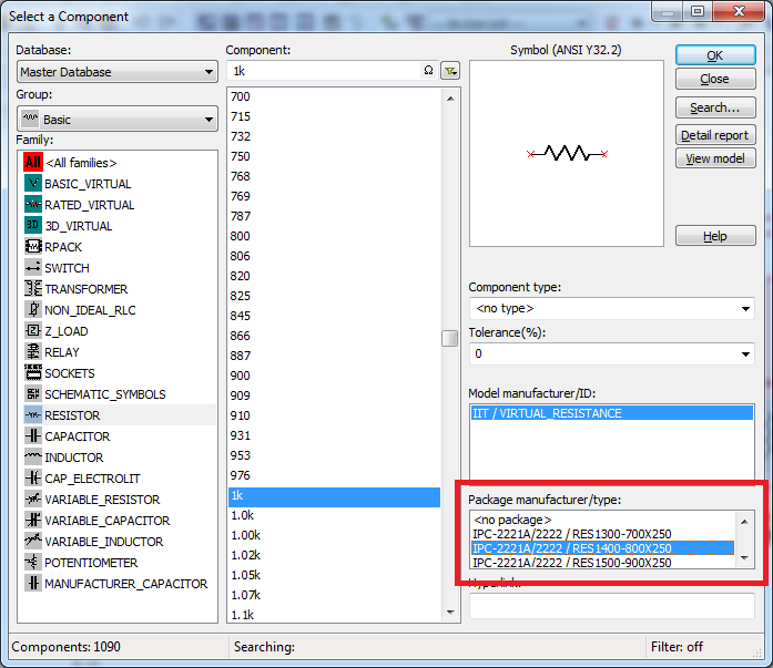
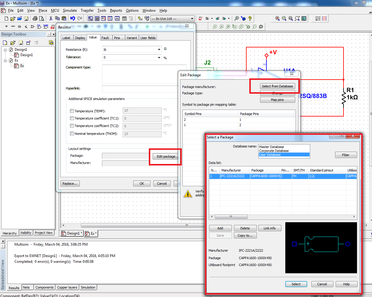
By default, when you place the RLN base, it has no assigned package. The package contains to Ultiboard layout information. Is this the message you saw said you, that the list of components in the spreadsheet was not exported to Ultiboard because they had no information about the package.
If you want to be able to transfer your RLC to Ultiboard components, you can choose a package when placing it down on the diagram:
Or you can add a package to a component that you have already placed. Double-click the component to open its properties and click on the tab 'value '. From there, you can edit the component package and select one in the master's degree, business, or the user database:
Let me know if this helps.
See you soon!
The f
National Instruments
-
Transparency of body part 3D Ultiboard
My last edit session footprint editor Ultiboard rendered part 3D of the body as being transparent. It was nice that I could see all the stamps hidden under the part. When I started re UB it was back to the solid rendering.
Someone knows how to turn this 'feature' on intentionally? UB14.0
OK, I've figured this out. Double click with the right button of the mouse on the preview 3D and it changes from solid transparent.
-
Multisim for transfer Ultiboard Glitch
Hello
We have made many PCBS using Multisim as our software for schematic capture and Ultiboard for layout. The last room back does not work because the netlist in the schema is incompatible with the netlist in the provision of one piece (which is used several times on the map). Not only all the pins are reversed, but one of the pins is quite non-connected. Since the 8 pins are connected to the schematic side, this clearly isn't simply a matter of mixed up of PIN, but when I annotate with impatience, it is said that found no difference.
I went through and double and triple checked the symbol, the footprint and mapping of the PIN, and everything is OK. As a witness, I created a new schema with nothing else that the part in question and transferred to Ultiboard, and everything was OK.
Everyone knows about this problem before? This is a known bug and is there any workaround or recommended solution to avoid something like this happening in the future (outside routing by hand and without taking into account the ratsnest altogether).
Thanks in advance for the help!
CDM,
Please contact our support group. You should not see this question in v11.0. I'm not aware of the important issues with annotation front/rear, since we redesigned the annotation capability and improved reliability in v11.0 (from 10.1).
http://sine.NI.com/apps/UTF8/NICC.call_me -> select ask support
Kind regards
Pat Noonan
-
Formate Ultiboard Enterprise support export Valor ODB ++?
This question relates to the request of the House of PCB Fab I treat for an export format that works with their new Aegis 'CircuitCam"System. are there characteristics "additional export format" in the Enterprise of Ultiboard version?
Thank you very much, Tod
There is no 'Ultiboard Enterprise' version, so I'm not sure that you are trying to compare the versions, but there is no export ODB ++ to Ultiboard.
See the NI Ultiboard Professional product features for an overview of the professional features.
-
Try to migrate Ultiboard user database of the 11 to 12 worm
I updated my software to Ver 12 and noticed that my user database have not migrated. Then I copied my worm 11 critical db space worm 12 and restarted Ultiboard. On call for Ultiboard, I received a diagnosis indicating that my user database was the wrong version and that it would not be usable. So, how can I migrate my database to the user, and why was it not this part of the update process in the first place?
Hello smh55,
Tools > database > convert the database should do the trick...
-
Difficult to change the width of talk about thermal discharge in Ultiboard
I'm trying to change the width of talking thermal relief of various buffers on an existing Ultiboard layout done with an earlier version, and that they do not change. Can I change the "type" for x or +, etc. but not the width of the shelves. Is there some global setting prevent this? That means "use the polygon settings' when you set the type, and how will this affect the width talking thermal relief? I see nothing in the help file. I also searched help and the user manual for what happens if I select Auto for width, but I can't find any instructions on what it means.
I was able to confirm the behavior you're seeing where the width of the rays is limited by the width of the measurement of the surface of the coppe / diet plan. It is certainly not intentional and I produced it for R & D to address a defect report. I am very sorry for the inconvenience that was done to you.
There are no files attached on your post so I can't confirm your actual designs. Please let me know if the workaround solution (to adjust the width of the measure) will allow you to get the results you're looking for, despite the incorrect behavior.
Jeff
-
AUTOPLACE Edition education Ultiboard Version 11.0 (11.0.278)
Hello from Germany!
I can´t find the automatic agent in Ultiboard. I work with the edition Version 11.0 education (11.0.278).
If I look in the Release Notes OR Circuit Design Suite I find "automatic alignment"... (= Autoplace!).
Maybe someone can help me to find it.
Thank you
Sascha Kruse
Hi Sascha,
automatic agent is not included in the edition of education. This feature is only available in the Professional editions (full and Power Pro).
Kind regards
Fernando
-
Is it possible to edit the ultiboard log file (v10.1.1)?
I made the mistake of removing parts of a design Ultiboard and will then mark them up a very different conception of Multisim. Now when I try to renumber all reference indicators and annotate back to Multisim, he wants to remove all items first and then make him renumber. It is with the version 10.1.1. Is it possible to edit the log file if it doesn't do the renumbering of part?
Since this drawing took me 3 days to deliver, she really sucks if I start more can renumber parts.
I thought that the answer would be no because I think they address this version 11. But I found a way to 'cleansing' of the log file. I created another design, just copied and pasted in the new design. At that time, I had the same exact design, with the same reference indicators and all traces of tact, but none of the nets. I've annotated front of Multisim and introduced all the nets without error. Now I have renumbered all parts and retro-annotation. He wanted to stick all over again but this time that Multisim just said "not supported - add part xxxx" which meant that there nothing done. But she made the reference of all changes of the indicator. Yay. Even if she was in trouble with multi-sectioned parts. He would get a right door, but the rest would be something different with "xx" in the reference indicator. As "Uxx6A". So all I had to do by clicking on the parties and select 'replace the component' and it will show the indicator just with a single gate used and I just had to select the same door.
So problem solved.
-
I can't get rid of the layer names in the general properties tab layers PCB Ultiboard
A bunch of DXF layer names have been concluded by Ultiboard 10.1 error a few years during a DXF for import operation. I have recently updated to 12.0 and hope that the old layers would be eliminated. I wanted to get rid of them for a long time. I tried to delete the file ub_config in AppData, but it didn't remove them. Is that all you can think to extract them from the clutches of the program? Thanks, Tod
Hi Tod,
I suspect one of your design files is the cause. If you go to Options > CFP properties > general Layers, you see here DXF layers? If you see the layers, you can select it and then press the delete button?
-
Ultiboard make printer laser method
Hey guys im new to this program. I got a diagram, transferred to ultiboard, autoplaced and routed automatically. I have some problems. One I want to use the method to fabercating the real jury laser printer. When I'm putting my copper layer on the top not the bottem highway. How to fix this? And also I need to print a mirrored from the actual size of the copper layer. I couldn't find that. Sorry for asking here guys but I spent like 2 hours looking in the help file. Im a student in electronics and this is my first design of the card.
Kevin
Hey Kevin,
It was the missing piece of information. Boards front has had problems and have been removed in the latest version to avoid problems such as this one. Of course, it is always possible to create them (it's just a two-face where it is not used).
For your second question, you can change the shape of the cushion directly in Ultiboard.
- Make sure that the selection filter, Activate by selecting Pads and SMD by selecting activate Pads , are turned on (I don't know if this part is THT or SMD, so this covers both cases)
- Press the Select button, then click on Edit > properties (double click also works)
- You can change the form in the dialog box that displays on the tab of Pad . If it is a part of the THT, you will need to change the shape, on each layer of the Board of Directors.
A last suggestion (dealing with nestor) is to make sure that everything is once you're done. You can do this by printing the Board with footprint of paper and making a Visual check of the part.
-
Ultiboard 14 project files are compatible with Ultiboard 13?
A colleague brought by a project file, it creates 14 Ultiboard for me to watch, and I was unable to load with Ultiboard 13. These are totally incompatible?
Hello
as much as I thought, MS14 open *.ms13 files
but
MS13 does not open the files *.ms14
Best regards
Michael
Maybe you are looking for
-
Pavilion 6650z: upgrade Windows 10
I was wondering if an upgrade to Windows 7 SP 1 Windows 10 could prove useful. My desktop computer Pavilion meets all the hardware requirements to run Win 10. It's a CTO in January 2011. I've already tried an update to Win 10 on-site the weekend of t
-
Cannot install Toshiba Virtual Sound on Satellite A100 - 01 L
My new Satellite A100 - 01 L, PSAARE Have a problem! When I want to install Toshiba Virtual Sound Utility said installation that I have incompatible computer!Whats wrong here? Why I can not install this utility?
-
Simple pass stopped working all of a sudden
Simple passage no longer works, on my windows laptop 8.1 Envy 15 j009wm, suddendly today. HP Recovery Manager and tried to fix it, but it did not work. When I manually click Simple passage, it does not... ie the page starts to come, but then it flash
-
Hello... I want to ask that if I improve my current DDR2 memory in my HDX-16 what is the speed MAX of memory can buy for this model? Thanks in advance!
-
How can I set password lockout policy on the XP Home Edition...
How can I set password lockout policy on the XP Home Edition...