waveform, with an average of results using labview to O-scope
Hello fellow engineers! I'm a first-yeargraduatestudent in CHEE at the University of Houston. Basically, I know nothing about labview. I am trying to program an application that looks like this - I collect a waveform of the signal of O-scope. This waveform does not change its characteristic shape. I need to find the wave form average of waveforms of N (100 for example). Thus, the slight changes (or noise) in the feature of form during the period mustbeaveraged out and I need to have a resultant waveform that represents the average waveform over a period. So, basically, I'm collecting the wave several times (for example 100) on a single period. The O-scope that I use now is Tektronix TDS 2024 B. It communicates with the computer via USB. The version of labview is 8.5. For now, I am able to communicate with the computer using our o-scope through labview. I already downloaded the driver of instruments of your Web site. It turns out that the program can give me only the average result I can get directly from o-scope manually. I need to have more say on average (100) using labview. I wrote a program that relies on the instrument driver that is downloaded on your website (for loop part is average, the waveform). The program that I modified and an instrument driver are attached. The program cannot be fully open, if the driver is not put in the right place in the labview (under lib inst.) When I run the program, the average waveform does not appear on the front panal and signal waveform file is not saved correctly. Is there someone can find where I did wrong and it develop for me? Because I barely know Labview, it will be even better if you can add an image or program that you have changed. I'm waiting for your creative ideas.
With the best regards,.
--
Weiye
Tags: NI Software
Similar Questions
-
reading photoplethysmograph waveform with serial port on PC using Labview
Hello world
I'm gaining time real Photoplethysmography waveform of serial port using Labview.I have managed to acquire data from serial port by using the following features:
-Baud rate: 38400
-data bits: 8
-stopbit: 1
-No parity bit
-Time delay before reading the serial port: 10 ms (according to what was written in the manual that every 10 ms there is a frame in serial port)
After the reading string will be converted to byte array to be able to extract the bytes associated with waveform (1 & 2 bytes in a frame) even for SOP2 (6 & 7)
(what is read in serial port is in decimal and must be converted to hexadecimal based on what made the software of prodeuct for some result.that in the waveform properties, I chose the hexadecimal representation)
Then, as mentioned in the manual, I associate these two values to draw the waveform.
Although I used the filter band digital waveform of pulse but not significant pass that was seen (cutofffrequeny:10 high low cut-off frequency: 0.5).
I have attached my program and result in front of Panel and manual for the sensor. The result is still far from what is supposed to be. I was wondering if you could help me and let me know your opinion on the program and the protocol used. I have to get the result as soon as possible. Please let me know if you need more information.
Kind regards
-
Dynamic link with after effects file results using different fonts
I have a scene first pro and I use a dynamic link with a legacy file where all my titles and text effects are made.
The font used in the aftermath of file is not used in the file first pro. Only a few times. Even in a text effect, he uses the correct font for a few seconds, then the default font.
Very strange. How is it possible. Everything is OK in the after effects and in first pro file, it is not.
Can someone help me quickly here. Thank you!
.. .and while typing the last message he set himself.
I erased the caches for Premiere Pro and After Effects in the media of each Preferences section.
Then I opened the sequence of the Premier Pro and he settled himself later.
-
How the interface with a multimeter Keithley 2000 using LabVIEW
-
need help with an order first level using LABVIEW PID control process.
As the program begins to run the PV value also increase when it reaches the SP is not settledown instead it stops.
Have you tried on the NEST? There are a bunch of examples here on the forum
-
With an average of a spectral waveform and view / save
Hello world!
I am currently on a University project that consists on the use of Labview to obtain data and spectra of atmospheric plasmas using a spectrometer Ocean Optics HR4000.
After not not using Labview for almost a year, I managed to get most of my knowledge back and I managed to display the spectral waveform, that I expect to get. However, as this is a fairly simple design I get a lot of noise and I would on average it for a graphic display more smooth.
I looked into a lot of messages from the forum, but I couldn't really find what I was looking for.
I also had a problem when you try to save the data and Spectra: I can't find anything in the directory of my VI.
In the attachment you will find the current VI I'm trying.
Thanks in advance for your answers!
Jeremy
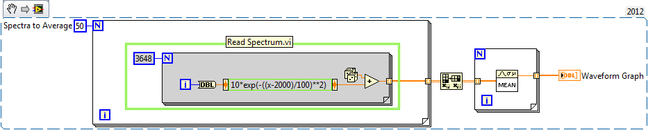
I wrote an example for you below. This is an excerpt from VI, so you can drag the .png in your diagram and it becomes code. Pretend that everything in the green box is your Subvi spectrum acquisition.
-Place the Subvi in a loop to run as many times as you like on average there
-Out of the loop For is a table 2D with individual spectra on the lines
-Transpose output, so individual spectra on the columns
-Enter the table another loop to take the average rank by rank (with an average of different Spectra togeter).
-Output is 1 d spectra average table
-
Deal with failure when using LabVIEW 2011 and DSC MODBUS communication
I'm currently reading from operating records a PLC with MODBUS/TCP. I confirmed that the PLC will update the values and in response to a MODBUS communication correctly by using a third-party program called Modbus Poll. However, when I try to query the PLC using the LabVIEW shared variable engine, I am unable to read the values of the same addresses that I consult with Modbus Poll.
My installation is simply to a PC directly connected to the controller via Ethernet without a router between the two. I'm using LabVIEW 2011 SP1 with the DSC module.
I opened the Manager of distributed systems OR to display the State of all variables in the Modbus Library that I created, and I noticed that the ILO CommFail permanently the value 'true '. All other variables with a 'read' access mode signal "failure of process". I tried to restart the process and stop and start the local variable engine without success. I also restarted my computer several times to see if any services did not exist, but this does not appear to have solved the problem.
Finally, I resorted to listening to communications on the network card I have the PLC connected via Ethernet using Wireshark and found that while Modbus Poll communicates with PLC, number of MODBUS and TCP packet is sent and received. However, when using only LabVIEW or the DSM OR communicate with the controller, there don't seem to be any communication on the network card.
Something that may be interesting to note is that I could communicate with the PLC and to read values with the DSM just once, when I understood everything first what address I should be reading of. All of this has stopped working shortly after. Prior to this, 'CommFail' was not generally set to 'true' with my current setup. Thinking it was my firewall, I have since disabled my firewall, but this seems to have had no effect on the problem either.
Any help on this would be appreciated.
So, I thought about it. It turns out that the IP address of the server i/o MODBUS must be set to the address of the MODBUS slave, not the local computer. The address of the i/o MODBUS server is defined by the navigation in the Explorer window projects, expanding the variable engine shared library for MODBUS and right click on the server MODBUS (for example Modbus1) item and select Properties.
In addition, the addresses seem to be shifted by + 1.
Thanks for the tip so.
-
Load a file in tiara with a use using LabVIEW
Is it possible to load a file into tiara with a use that is customized by using LabVIEW. I looked through the palette and see nothing.
Hi Siriusly,
I've added 2 additional lines of configuration of trainer to the use, and now that the last row of empty values has disappeared from a single file you sent me.
Brad Turpin
Tiara Product Support Engineer
National Instruments -
How to contact with SQL using LabVIEW 7.1... ?
Hello...

I want to create a system that deals with the database and stores the database to the server through SQL... Can someone guide me please how to contact SQL using LabVIEW 7.1... ?
Thanks for any help on your part...
You can either use the LabVIEW Database Connectivity Toolkit or LabSQL to communicate with the SQL data bases. Take a look at those and after if you have other questions.
-
Call a visual basic executable file with arguments command line using LABView
Hi all
I try to call a visual basic executable file with a command line using LABView 2014 argument. What I'm trying to accomplish executes an executable file that communicates with a device via a COM port. So, I would open the .exe with a command line argument to communicate via com 3 using the SYSTEM Exec VI. It seems that the command prompt window flashes and closes and then nothing happens. Not a lot of discussions about this on the forum. Any help would be greatly appreciated. Thank you.
With some programs, instead of passing in the string:
Somefile.exe
Instead, you can use:
cmd /c "C:\Full Path\to the EXE\Somefile.exe"
Can you tell us what exactly you are trying to run?
-
Possible to use labview with daq system not of NOR?
Hello
I have a daq system and the software from another company that NEITHER. But I want some changes in the software. If the opportunity was to make a new program with Labview.
Is it possible to use the old system of data acquisition? Is this compatible with Labview? Or I have to buy new hardware?
Thank you.
Hi VIassaks,
Good afternoon and I hope that your well today.
Thanks for the post.
LabVIEW can communicate with 3rd party hardware using the library function call is located in the tip under the functions Palette palette. If your equipment is equipped with a DLL at the driver level LabVIEW can communicate with the hardware. However, you must obtain documentation of the DLL so that you can create your own interface for the material of the part 3.
Another option would be if the hardware manufacturer provided LabVIEW VIs that control their material. You will not be able to use the screws (National Instruments Data Acquisition DAQ) because these screws use the DLL OR-DAQ, which is our software at the level of the driver for our DAQ cards. Other companies use their own software to the driver level to control their own material. Only the National Instruments hardware uses the NOR-DAQ driver that allows you to use LabVIEW DAQ screws.
Hope this helps,
-
Covered wagon with an average of analog voltages DAQmx
I searched through screws, I can't seem to find something that will automatically average numbers of boxcar fed into it. I am trying to create a feature of my software that will allow the dynamic configuration of the car covered with an average of some inputs. I would like to avoid hard-coding tables which are filled/rotation etc etc.. Any help is appreciated
Thank you
If you use a Functional Global to store the values and call that VI of two different screws, you will access the same data. You could use two Global in the functional shift registers and use a selector to place / extract data from / to the appropriate shift register. Only VI call access one commune VI at the time, so one of the caller of the screw will be 'blocked' until the first caller is done. This does not usually work for data acquisition applications high speed.
You might consider using named queues instead of functioning overall. You might be interested in this thread on the forums of LAVA that deals with boxcar implimentations. You create a queue for each data stream and can perform functions such as "preview" queue to get all items without actually removing them from the queue. If you use a LabVIEW 8.6, there is a new feature called with loss of queues. You set an upper limit on the size of the queue and "lossy enqueue" allows to add items at the end of the queue. If the queue fills up, then the oldest data element will be lost.
-
Strange behavior when using Labview to collect data from Tektronix oscilloscope tds8200
I hit a wall in trying to understand this one. The problem I have is that my application will not start the oscilloscope when it should.
I use an oscilloscope Tektronix TDS8200. My goal is to collect data from the oscilloscope using Labview waveform. First of all, my program initializes and configures the oscilloscope; This part of the program works very well.
The second part of the program begins the acquisition of data with the function 'Tktds8k Start or Stop Aquisitions.vi', which is to press the button run on the scope. The function "tktds8k to Waveform.vi" is used and should ideally return data, which I connected to a waveform playback graph.
When I run my program, the first part runs without a problem, but as soon as the program comes to the service get the waveform, the run button in the scope, which is green when running, turns off; the program then expires, and no data is collected.
Here is where it gets weird. I went through the debugging to try to understand this point, and I put breakpoints on the beginning and get shape wave functions so that I could scroll through the last part of the program. The program continues with the departure function, and the button run in scope is green. The breakpoint for the function get the waveform is reached and when I press on continue, turns the Run button and turns it off then back on almost immediately. data are collected, the waveform graph appears and the program ends without error.
I thought that the timetable could be the problem, so I did the program wait as long as five seconds between the functions of start and get the waveform and that did not work. I also tried to move the start function to before the configuration functions and remove start completely; no method worked.
is there any ideas on why, the program works when I enabled breakpoints and isn't when breakpoints are disabled? I'm sure there is an easy solution, but I was not able to find a solution.
I have attached a pdf that contains information about the functions of the Oscilloscope (tktds8k.pdf), and I have also attached my program.
-
with an average of 5 minutes of data - is no way
I need average 5 minutes worth of data, save this average and then again on the next 5 minutes of data, with an average of this data block. I tried to use the average function pt-pt in LabVIEW, but who seems to take an average continuous market, I do not want. I probably read data once every 0.1 seconds, so I can not used stacked registers at offset, because it would be not very economical. I thought to build a table, but I don't know how to remove all the data at a time on average to it in an efficient manner, and more I'm stuck on the concept of re - create the table/clear the Board after five minutes of data has been collected, averaged and recorded.
Does anyone have a suggestion? I would really appreciate any advice or suggestions on how to go about it.
Keep a running total in a shift register. When your 5 minutes have expired, divide the sum by the number of samples taken, the sum to zero and start over.
-
Power SVFA - with an average of question spectrum
Hi all
I used the power spectrum of SVFA to treat a signal from a trasnducer of pressure. All the options associated with this block seems to work very well with the exception of the settings on average. I used Linear/One Shot mode and assign number ofa averages 20. The prioblem is once it reaches 20, it continues to go further. I added a boolean flag to check if she treated the number required of averages, he did in fact. So now I'm stumped. Restart of the averagting seems to work as expected so.
Any thoughts?
Oleks:
The sounds and vibrations help file for the Modes of time on average, we see that this is expected behavior:
"In an average of peak-hold, the largest value of sound pressure level measured in all the previous values is calculated and returned until a new value is greater than the current maximum. The new value becomes the new maximum value and the returned value until a new value is greater than it. Peak hold is not really a form of averaging because successive measurements are not mathematically average. However, as with other processes of establishing an average, average peak-hold combines the results of several measurements in a final measure. As for the average exponential, the process of averaging continues indefinitely. »
So because Peak Hold do not average in the strict sense, it does not restart on average the number of averages you specified as RMS and the vector average which are a true average.
Tori, w.
Maybe you are looking for
-
Cannot load websites after a while
Firefox cannot connect to Web sites after a while. It will keep on the connection but no results. Sometimes, the page will be able to load. Other times, I need to restart the browser. I tried the things:1. disable the plugins and modules.2. the other
-
THE PROVISION IS THE 3.6 NOT LAYOUT THE 4.0.1IN RESPECT OF THE AID, IT SAYS I'M RUNNING 4.0.1
-
The fcpcmcia.sys file is not found on a Portege M200
Hello Someone at - he never understand the problem "the file fcpcmcia.sys is not found"? I saw in another post, but suggestions does not solve it and the post has been locked while I couldn't answer. I have a Toshiba Portege M200, who has the same pr
-
Question about RAM in Satellite A100-192
Hello! Help me please. I can replace standard Ram (512 MB, 533 Mhz) on nine with frequency 667 Mhz? So also, will it work?
-
I use airplane mode on my iPhone 6, with wifi and I still receive calls. I don't want to. How can I change?