What is the analog input of the NI PCI-6229 impedance?
I am trying to determine the effect of a 12 K resistor that is in series with an analog input of an NI PCI-6229 data acquisition card. Resistance of 12K seems to be part of a RC filter. I have a 0-10 VDC source this supply circuit. What is the impedance of the analog input of the NI PCI-6229 data acquisition card? If it makes any difference, the analog input is connected in differential mode with a 180K resistor to Gnd AI.
Thank you
RWB
Hi, RWB,.
The input impedance is classified in the specifications 10 GOhm. So, the effect of your k 12 resistance should be relatively low. Take care!
Tags: NI Hardware
Similar Questions
-
Hi all
I'm starting my first app using a card of RIO for the analog input and power (two PCI-7833).
My previous experience with DAQ systems was on PC so I'm especially familiar with DAQmx. It is my understanding that DAQmx is not really being used on these boards, there is no DAQmx tasks to play with.
So, my question is this: How can I dynamically set the range of the signal of the analog inputs so that I get the best possible resolution?
What I want to say in DAQmx if I know that the input signal is only 1 V pk to pk I can put this beforehand in the task.
Thank you!
OK, a little further digging shows the input range is set to +/-10V, is this correct?
-
What is the minimum response of analog input, through DSP online, output analog time?
Hello experts!
I want to know if it is possible to get a very quick response latency (~ 1 ms) sound recording (analog input), through online registration (DSP online), the presentation of his (analog output) processing, by using the DAQmx programming codes. My system of NEITHER includes NOR SMU 8135, SMU 6358 DAQ Multifunction controller and SMU 5412 arbitrary signal generator. I also have access to the latest version of Labview (2015 Version) software.
My project is on auditory disturbances, which inovles record vocalizations, manipulating the recorded vocalziations and then present the manipulated vocalizations. My current idea of how to achieve this fact triggered output voltage after reading the input using DAQmx Read samples. DAQmx Read output is filtered online and then passed as input for the DAQmx writing for analog output. For purposes of illustration, examples of code are presented below. Note for simplisity, codes for the trigger part are not presented here. It's something to work in the future.
My question here is If the idea above should be reaching ~ 1ms delay? Or I have to rely on a totally different programming module, the FPGA? I am very new to Labview so as to NEITHER. After reading some documentation on FPGA, I realized that my current hardware is unable to do so because I do not have the FPGA signals processing equipment. Am I wrong?
Something might be important to mention, I'm tasting with network (approximately 16 microphones) microphones at very high sampling rate (250 kHz), which is technically very high speed. Natually, these records must be saved on hard drive. Here again, a single microphone is shown.
I have two concerns that my current approach could achieve my goal.
First, for the DAQmx Read function in step 2, I put the samples to be read as 1/10 of the sampling frequency. It's recommended by Labview and so necessary to avoid buffer overflow when a smaller number is used. However, my concern here associated with the latency of the answer is that it might already cause a delay of 100 ms response, i.e. the time to collect these samples before reading. Is this true?
Secondly, every interaction while the loop takes at least a few tens of milliseconds (~ 30 ms). He is originally a State 30 late?
Hey, I've never used or familiar with the hardware you have. So I can't help you there.
On the side of RT, again once I don't know about your hardware, but I used NOR myRIO 1900, where he has a personality of high specific speed for the RT where I can acquire the kHz Audio @44 and process data. Based image processing is ultimately do the treatment on a wide range of audio data you have gathered through high sampling frequency and number number of samples as permitted by latency, please check this .
I lost about 2 weeks to understand host-side does not work and another 2 weeks to understand the even side of RT does not work for online processing (real time). Then, finally now I'm working on FPGA, where the sampling rate is 250 kHz (of course shared by multiple channels).
The complex thing with FPGA is coding, please check if the filter you want is given below as labview automatically generates some codes of some filters.
Most of them will work in 1 SCTL IE if your target has 40 MHz clock algorithm will run in 25 ns. That's what I was looking for, I hope you

See you soon... !
-
iMac with Thunderbolt - how to get the old analog inputs
I hang up my old Mac Pro in 2005. I used it to record video cameras and mainly music best of my plate rotating and stereo system - vinyl and CD disks via s-video and RCA cables and Firewire for Mac Pro.
The iMac 27 "new is primary Thunderbolt and I can't find a Thunderbolt conversion box so I can enter my analog input RCA and S-video signals. No indication on the Thunderbolt converters 'both ways' I can't exit analog in the iMAC, then the iMac as well?
They certainly run Final Cut Pro X on the iMAC, then how people get their old media and music in the machine?
I'm about to talk to the local Apple store, but the chances of finding someone who knows what they are talking about with the iMac, Thunderbolt and analog input is going to be a stretch.
Al Donn
You can probably use a converter DV firewire as a Canopus ADVC 110 http://www.bhphotovideo.com/bnh/controller/home?O= & sku = 349146 & gclid = CLSF0_qUnswC FQ8vaQod9VkFFw & is = REG & ap = y & m = Y & c3api = 187... and then an adapter firewire-crush.
-
read the multiple analog inputs at the same time
Hi all
I use USB-6001 and want to develop an application to multiple tasks in C++. I try to read several analog inputs at the same time, but got some errors. To put it simply, I copy one of the sample code to read in analog data in a channel, and then turn it into function. Then I call this function to thread with the names of different poles (for example Dev1/ai0, Dev1/ai1) and I come across this error:
"The specified source is reserved. The operation can not be specified such complete"code of State-50103
I have search the forums, this may be because I use the hardware timing in this function, and this material timing cannot be used simultaneously by multiple tasks. I may have to put all the lines, I want to read in a single task (such as Dev1 / ai0:1). This way I can read two lines at the same time. However, when I try this, I encounter another error:
Status code "buffer is too small to contain the data read" - 200299
So here is my question, what should I do if I don't want to read the multiple analog inputs at the same time? Is the thing that hard time cannot be used by several true task? If I have to read several lines to a single task, how to set the settings?
-
Several analog inputs seem to change any of the other (details DAQ: 2120 BNC and 6062E)
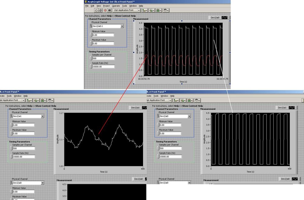
I use the BNC 2120 DAQ board connected to the data acquisition card 6062E to record two analog inputs. An entry is connected to ai0 and the other at ai1. Example vi: "Acq & graph int clk tension" has been used to measure the two entries with the value read NChan NSamp vi (channels being dev2 / ai0:1). The output is the top graph in the image. However, this seemed a bit strange to me that one of them should be modulating with a different frequency. When I record both entered individually (two in low pictures) they are indeed different since the entries shown in the top graph.

Why this would be the case, and how can I overcome this to measure the real signals?
Thank you!
The E series card takes the samples as soon as possible. Thus, for example,.
If you have 16 analog input channels but you only read of
channel 0 and 1, the map will show the channels 0 and 1 right
After and then wait 14 'ticks '. What's that little run-in
the origin of the afterglow.
I think you can get the card to wait a certain
number of ticks with a property node. I have attached a screenshot. You
can find the property node in the palette of functions >
Measurement of e/s > NOR-DAQmx > node Timing. Expand it
Property node so there's two entrances. The properties are in
Left click on the node and going more > converted >
Its properties delay units and sampling clock delay and delay that
you want.If the phase is important so the above is not the best
the option because it causes a delay in phase. So, if you need true simultaneous
sampling, then you will need different hardware. The S series is everything
simultaneous sampling.Or, rather than the Delay property and delay units, try the Rate property
find more > converted > rate.If this is not
work either, you can move the second signal source to, say, AI8 and
Connect everyone to the ground. Readings for these, but just do not take into account
the data. In this way the ADC will sag to the ground at the time where that can happen
the second string in the way so that you should not see this frequency
ghosting on the other channel. -
reading of the analog inputs with RPC
Hello
Because LabVIEW can not handle this (in VI; the value that you have saved the excel file has not been the same, that I saw during the measurement...) This confused me for a long time
 ), I want to write a C++ program (IDE: Dev - C++) which can read & record 2 analog inputs of the NI USB-6009 box. For this, I looked for an example of National Instruments and I found a little. But my problem is that I can't even use any example, because it has always held a mistake, after that I have compiled and started.
The error once the task has been created and has the :-200220 error number with the description "device identifier is invalid. But I do think that its invalid, because it's the xP example
I must say that I am new in programming C++, which means I could have a rookie mistake. And I couldn't find documentation or something for the NOR-DAQmx library.
Someone has similar problems with DAQmx and C++ and know how to fix? I don't really know what I can do now without a working example or documentations...
Hi Mario
It's the same thing. You didn't just save all of the data:
Please take a look at my comments in the attached VI.
Christian
-
PXI-6071e offset drift on the analog inputs
Hi, I have three cards PXI-6071E, sitting in a PXI-1042 chassis that is controlled by a computer with windows XP. The 6071Es are connected to the SCB-100 break out boxes that are wired to a pannel of BNC female Panel Mount on twisted pair.
I noticed that all of my analog inputs will drift around-10 V to + 10 V if they are not connected to what whether forcing them to a certain tension. This has always happened. We also see a bit of crosstalk between channels. For example if I open a panel of test in the measurement and automation Explorer I can watch the voltage read on the drift tickets through their full range, and alteration of the signals on nearby channels will appear on the channel, I am able.
Is this just standard behavior and to predict? Is there something more I could do to minimize this drift and crosstalk? I am trying to reduce noise in my system so I figure optimize my DAQ could not hurt.
Thank you
With nothing plugged into the catch to high impedance, drifting you see is quite normal. The front end of the circuitry builds up a charge, crosstalk is proabably due to the multiplexer input (did not check but I think that the 6071 has a) transferring the load to the other channels when they are analyzed.
Search the Forum of ghosting, you will find related discussions.
-AK2DM
-
Read the counter timeout in synchronized to count-analog input
Ciao, Giovanni.
The two tasks are run in parallel so there is no guarantee which task starts first. I suspect that when you are away from the counter samples, it is because the task of analog input before starting the task of counter. In this case, the task of counter would be ready to accept examples of clock and may be missing some edges of the clock at the time wherever he is started.
One way to solve the problem would be to use the wires of the error in order to ensure the time started the task of counter in front of the task of analog input. You can also use a sequence structure to do that.
The counter is sampled on each edge of the sample clock HAVE no matter what you set the 'rate' of entry to the. When you use an "external" clock (external to the task that is), the driver uses just the entry rate to set some default parameters (size of buffer for example).
If you have any questions, feel free to ask!
Best regards
-
What is the best way to get direct playback of audio input?
I know it must be easier that I am making, but somehow I can't seem to make it work right. I use a myDAQ taking into data analog voltage and eager to play back (with some filtering) through its built-in audio system taken or my computer. Seems to me do not understand exactly how the DAQmx voltage output is supposed to work; using anything else that the screw express so far just gave me errors. Using the express screw, I was able to taste and delayed reading data blocks, with spacings between them (not exactly ideal).
An example of code could greatly help to understand how this process should work and would be useful to many other people as well. Thank you.
I think that this example does exactly what you want. It supports analog input of the myDAQ, then has the ability to add a filter, and then she out back. I can't remember where I found it but it was in a workshop to learn how to use the myDAQ and LabVIEW.
-
Toggle the analog inputs and tasks of output on the same card in LabView
Hello
I'm relatively new to LabView and am trying to find the best way to switch between reading and writing tasks on my PCI-6024E. It seems this would be a common thing to do, but I found no good documentation or any relatable example program. Basically, I would like to be able to monitor certain analog inputs and then write that some outputs if an entry is in accordance with certain specific conditions (say > 4 Volts voltage). It is my understanding that you can only signal (input and output) types associated within a single task in DAQmx. I also understand that you cannot have multiple tasks running at the same time on the same material/map, otherwise you get a: 50103 error 'The specified resource is reserved. Calendar is not really all that matters to me, but quite synchronous and effective would be nice.
I have attached a sample program that shows more or less what I'm trying to do. I want to follow several analog input lines (AI0 AI1, AI2 and AI3 and) effectively at the same time. If certain conditions are met, AI3 > 4 Volts, then write 5 Volts for analog AO0 and AO1 outings. I also want to maintain output at 5 Volts up to AI3 falls below 4 Volts. Is there a better way to pass the task to read and write than what I've done here? In a sense, all I really do is toggle of a state machine if the required conditions are met and if start/stop tasks of reading/writing necessary.
One last question, is there a way to display the four channels in the waveform graph using the 1 d NChan 1Samp mode so I can have a time chart and indicators?
P.S. I'm under LabView 2011 on Windows 7. Your ideas and suggestions are appreciated.
Thank you
KJ
I also understand that you cannot have multiple tasks running at the same time on the same material/map, otherwise you get a: 50103 error 'The specified resource is reserved.
This is incorrect. You can't have two tasks of the same type running on a single card. You can have an analog input and analog output task running simultaneously on the same hardware.
You are right that each task can have only one type of task (entry or exit). Discover DAQmx examples in the example Finder to get examples of synchronized input and output.
PRO TIP: In the Finder of the example, go to the drop-down list in the lower left corner. Pull down and select Add Hardware. In the pop-up window, add your PCI-6024E to the right pane. Click OK in this window. Then in the main window of Finder example select your hardware from the drop-down list and check the filter results by the hardware. The example Finder then only you will show examples that are out-of-the-box compatible with your hardware. I am sure you can find something to fit your needs here.
-
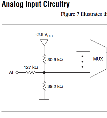
Cut-off for the 6008 analog input voltage
I am using the analog inputs NI USB-6008. The specification says they have a 144 k ohms input impedance. But it does not say what is the cut-off voltage. If you leave a disconnected and measure the voltage you will get 1.4 volts. So I guess it's the cut-off voltage, but it is not spec'd.
Someone agree that these Amnesty International isn't terminatied by 144 k - ohms to 1.4V? Is this in the documentation somewhere?
Figure 7 on page 16 of the NI USB-6008/6009 User Guide and specifications shows the strange input of this unit circuit.
Lynn
-
Registration of the analog inputs in continuous (Clipping)
Material:
(1) USB NI CDaq-9174 chassis
(2) NEITHER 9234 Analog Input Modules
(1) digital input module 9402 OR
Goal/Requirements:
To read the analog inputs continuous only in digital input is "high".
Problem:
Timestamp in log file prooves that logging is not continuous. It seems that the first seconds of 0.6 of every second is recording, I guess the other 0.4 is used to write custom? I can't use VI SignalExpress for this application because logging must be triggered by a high digital input.
File is attached. Thank you all!
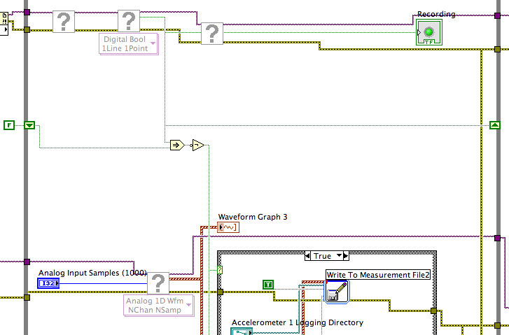
To detect changes in the digital input, you need to compare the current value to the previous. The easiest way to do this is to plug the output of digital playback on a shift register. The Boolean function involves will tell you when a transition has taken place. See the central part of the image below. If you exchange the true and the false case of case structures, you not the inversion function. Look at the help file for more information on what the function actually implies.
You must also change the wiring of the name of input for writing custom file FIle.vi so that the name is automaticlly changed. Depending on what you want the naming system to be, that it can be simple or rather complicated.
Lynn
-
Test the analog inputs in a PCI-6013
Hello. I m using a PCI-6013 OR DAQmx 9.1.1 with Labview 8.2 (sued) WinXP. The jury has undergone an immersion in water during a flood but was cleaned, recognized by WinXP and NIDAQmx.
I have run the Measurement & Automation explore and use the test under option OR-6013 'Dev1' panels 'devices and Interfaces. Here, I can see that the digital and clock output work perfectly (I can change the State of the digital channels and duty cycle and frequency of the clock). The problem arises when you try to measure an analog voltage. I tried on several cases not all analog channels using NRSE and differential modes (switch accordingly connections).
The signal comes from a (4 Hz, squares and sines, 5Vpp) signal generator via a CB-68LPR connector.
I only see something comparable to the entrance of singal when you use differential inputs (signal connected by J57 and J23) AI7, but the signal I see comes with 100 mVpp instead of 5 Vpp (I can see changes in the shape, every time that I have spend of a sine, square, ramp...). I also tried connecting J23 AISENSE (J62) and AIGND (J67), to avoid the problems of floating source. The same thing happens when enter and set up the acquisition by the vicinity of data in the Explorer of Measurement & Automation. I m using the reach of the signal in the different ranges, tried with 04:55, -1 to + 1, 09:50... When you configure tasks NIDAQmx I choose to read different samples (100, 1000, 10000) rate (100 Hz, 1 kHz,...) and combinations. Anyway, the input signal is always 4 Hz. I checked the signal with an osciloscope and I see it perfectly.
Is it possible to have the broken while the digital and general-purpose analog input clock outputs are OK? Y at - it a tip for the connections I should know about? Thanks in advance for any guidance!
Thank you both, KateB and MarisolM for your answers.
I made several the tests con señales DC y con señales senoidales, instalando placa en back different computers, y no obtengo resultados positivos, is spite of what el self-test selling well. Seems that the Plaça realmente esta fallando.
I did several tests with DC signals and senoidal, installing the card in two different computers, without positive results, even if the self-test is OK. It seems that the Council really works hard.
Are concentration cotización por su reparación. Gracias!
-
Synchronize the clocks of 2 PCI cards for analog inputs with e/s digital reference
I'm trying to synchronize the clocks of reference of 2 PCI cards so that the analog inputs are synchronized. However, my appilcation has also digtial e/s on two cards, and who apparently made the mistake DAQmxErrorResourcesInUseForRoute_Routing. This discussion describes a similar problem, but the solution was to just put the reference clock to the slave device, who had no other tasks running on it, so what mine does.
Is there way I can synchronize the clocks of refernce without interfering with the digital I/o?
Thank you!
PS: My application is in C++.
The reference clock is really a lower-level component that is shared by all resources on a given device. All tasks on a given device must use the same reference clock. So if you use DAQmxSetRefClkSrc for a task, you can use it to set the same value for your other tasks.
Best regards


Maybe you are looking for
-
It's my all first time owning and you use a router, so I have a few questions that I would ask. 1. my router connects (with flashing lights) constantly, or should it be unplugged when not in use? (By fear it overheats). 2. If I stay connected to a w
-
Message icon new blackBerry Smartphones won't go away
My new message notification icon says I have 2 new messages and will not disappear. I checked all my boxes e-mail and sms and mms and even deleted all messages. I rebooted the unit several times and it will still not go away. anyone has a solution or
-
Is it possible to see the names of the places for the uploaded images of office?
I downloaded several collections of images Fund (lightning, moon, scenery, etc.), but cannot see where these images are taken. My office of Bing puts a new picture every day and I can move my cursor over the "i" zone and see where he is. Is anyway
-
How to disable the datepicker based on the selection in a table list
I created an example onhttps://Apex.Oracle.com/pls/Apex/f?p=85310:23:9121532652163:follow-uphttps://community.Oracle.com/thread/1119800but no luckMy needs: -.with selection N dymanic action datepicker should be disabledand now, I think I need help.an
-
Problemi lettura PDF tipo .p7m ed sommergibili add on.
Ho CD nel PC con Windows 10. Non riesco a leggere i PDF con .p7m extension.NEI download del sito ho trovato the QDS .it che should risolvere addon addon it problema.Ho downloaded the my quando vado ad installare addon, device he message che serve tur