Wiring - PXI-6624
Hi all -
I have a request that I need to use a meter, we chose PXI-6624. I'm really good with the rest of the material, apart from FPGA and RF meters are only lines that I've not used. I'm running into some difficulties to understand how to configure my son on the 6624 and thought I'd ask here.
I have an optical sensor (Monarch Instruments model ROS) that I'll have to watch the impulses on. Its got 4 wires coming in the distance, a commune, a signal, a + V excitation (10V) and cable shielding (IE common). I am also connected to an SCB-100 using their 100 flex cable.
The thing I'm getting hung up, each meter on the module has 10 terminals assigned to him. I continue to go through the manual, but I can't understand. Went to NEITHER and the engineer he basically just copied and pasted the same part of the manual I did not understand. If you ask for more details on the portal + / for example, the response I got was 'you can if you want to signal that you are using the pins of the door the door '... I guess that means that you can use these pins as a switch to take the signal or not, as you would the door on a FET used as a switch. Just one example of how detailed responses are :-)
In any case, I am reading and looks like each entry almost has multiple functions that overlap, but I'm unable to digest it. Can someone help with the wiring on this?
Cordially - in the short term, I have 1 sensor which will include rpm for 1 pulse per turn. We also want to make direction which will need a second sensor with the set of two upward slightly as the squaring function requires. Only two will have only 1 pulse per revolution, rather than an encoder with say 120 pulses per rev. Should subsequently over them both, but I think that if I can figure out exactly one that I can use it to understand the rest of the installation on my own :-)
Thanks a bunch!
External connections:
Commune of sensor connected to the source - meter
The connected sensor signal to source + meter
Any signal of door that you would use for this application would be generated internally by using another counter and then routed internally to the door of the counter which counts the external pulses. In this case the door signal would provide a specific window of time count impulses. An example could be measure RPM. If you decide to measure the pulse for a full minute, with accuracy what a minute? If you do not exactly one minute, your RPM will be incorrect. Calendar of the software will not work.
Tags: NI Hardware
Similar Questions
-
Measure the frequency of the pulses PXI-6624
Hello. I work with a PXI-6624 and am interested to make measurements of pulsed frequency for frequency and duty cycle on its inputs using DAQmx.
When I go to create the virtual channel, however, I have error-200431:
"Physical channel selected does not support the type of measure required by the virtual channel you create."
' Asked the value: pulse frequency.
«You can select: frequency, period, pulse width, period of Semi, separation of the two edges, Position:...» »
Is this card really not capable of doing these measures of pulse frequency?
Yes, the "Pulse" (not to be confused with "Pulse Width") measure was introduced with STC3 of OR including CompactDAQ and X series devices.
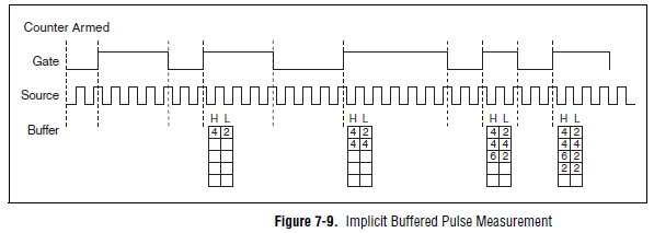
Measuring the pulse:
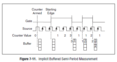
However, you should always be able to measure the frequency and the duty cycle on your card with a half measure:
The half measure:
The images are in the X Series user manual.
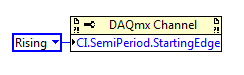
The difference between these two modes boils down to how the data is stored and implemented in buffer on the map - with the period semi method that the material does not distinguish between high and low samples and puts everything in a single buffer. However, if you start the meter on the song (see below the node property), then you would know the order of low and high samples in software, and are easy enough to calculate cycle frequency and the duty of this.
Best regards
-
How does one change the setting of the PFI on the PXI-6624 line filter...
Hello!
Please post on the Forums OR! I found a knowledge base that deals with that specification in detail. In addition, you can find TIO help this KB pointing to a good resource. Take a look at the attached screenshot. The digital filter property node can be used to change the filter settings. I hope this helps!
-
Hi all,
This is my first post so I apologize if I missed something and also for my English
We have conducted many years successfully applying LabVIEW RT (version 8.5.1) on a PXI-8184 (2 PXI-4472 modules, 1 module PXI-6624, chassis PXI-1042, 1 module PXI-6224). In our maintenance protocol, we loaded a picture of the traditional configuration of PXI (that we always use), using the system replication tool, as we usually do.
A few days ago, we did it. After the application has started running, suddenly restarted PXI. Since then, the PXI application always restarts junk.
This does not happen if we run the application directly from LV (no build request).
It is important to mention that we have no trace of falls or visits that could affect the integrity of the PXI system. We tried different solutions, but nothing happens (resetting, reinstalling,...).
First it hardware or software explanation to this? (watchdog, CMOS).
I would really appreciate any comments.
Greetings.
Roberto.
-
How to count the edges within the great period of door?
Hello
I use a PXI-6624 counter/timer in Visual Studio C++ with Meassurment Studio.
I want to count the edges on a signal within a high period of an input signal.
I found the documentation entries "CTR n CBC", "CTR n GATE" and "CTR n to THE.My idea is simply configure the counter 0 to count the edges on CBC by blocking via DOOR.
can be an example to my problem in the installation of nor, but above all I do not understand the description of landscaping.
to find a good example, you must know the name of the function you want to use.
can someone tell me the good examplename for my problem?
What call configuration should I use?a little less important than my first problem is a similar.
I want to count the edges on a signal between a start trigger and a relaxing stop.
SRC-> signal
DOOR-> start signal
To THE-> the stop signalI found a way to count the edges of the internal clock between start and stop (2 Seperation of edge), but not for an external signal.
can someone help me with this? especially with the first.
B
Hi John,.
Thank you for your help. It works very well.
I had a few problems with how the timebaseSource should be implemented.
Finally, I found the solution.
for those who do not want to search long for the code, it is here:
Create the task
CNiDAQmxTask ("CITask") m_task;Create the meter inlet channel
m_task. CIChannels.CreatePulseWidthChannel ("PXI1Slot16/ctr0", "",)
atof (minimum), atof (maximum), startingEdge,
DAQmxCIPulseWidthUnitsTicks);Retrieve the channel to change
CNiDAQmxCIChannel chan is m_task. CIChannels.GetAll ();
Fix the DOOR Signal
Chan. SetPulseWidthTerminal("/PXI1Slot16/PFI38");The value of the Signal SOURCE counton
Chan. CounterTimebaseSource = ' / PXI1Slot16/PFI39 ";CNiDAQmxCounterReader myCounterReader (m_task. Stream);
Double measuredWidth = myCounterReader.ReadSingleSampleDouble ();Thank you and goodbye
B
-
Hi all
I have to do a test system optimal hardware configuration OR for an application where the system should simulate Serial interfaces, interfaces to MIL STD 1553 and analog, Digital O/Ps & I / PS. Modules OR for the best match for this requirement were NI PXIe4322, 4300, 6363, PXI-6624, 8430/4,8431/8, Pickering two rtd PXI cards and a card of 1553 PXI SMU-1075 controller SMU 8840-frame. BUT this current price of configurations will on budget than we expected. for this reason I think to change this part and part PCI system in 6363,6634 tax SMU system, serial interface cards and card MIL 1553 with a PCI/PCIe platform and keep the rest of the map with the SMU platform chassis and eliminating controller SMU 8840. So can I use MXIe controllers to implement this system of type test so that I can put all the pci cards in a high-end modules SMU and PC and industrial PXI chassis SMU (1065/1075/1078 one)? If so please guide me what controller MXIe to choose and what would be the compatibility problems that may occur with this type of system in the future.
Thank you
My experience with USB has been nothing else to headaches. So I wouldn't go the route of USB. Normal PXI slots can also accept the cPCI, so you could look for those as well. If you just need a very simple map of 1553, I'd go with 1553 Excalibur cPCI card. I used their cards and they work fine. Drivers LabVIEW need a cleaning, but they can be used. This card is a simple send and receive, so if you need to do some testing of weird signal integrety (I don't remember the number of test at the top of my head), this card will not work for you. But this card was sever thousand dollars less expensive than the GOAL cards, I also used.
-
Wiring question: PXI-2501 1 wire 48 x 1
Dear friends,
I need wiring help. I have a setup of the PXI-2501 for 1 wire 48 x 1 with a block of connection TB-2065. I have an analog signal entering the block I want to switch between 5 different LEDs. The incoming analog signal has two sons (positive & GND), and my Bank of LEDS has 6 wires (5 separate positive & a shared GND). I have reviewed the documentation section 'NI Switches Help' 'topology, NI PXI-2501/2503 1fil 48 × 1 Multiplexer', but he has not quite figured it. Can I connect my two ground wires and then connect the rest like this?
analog input
+ 1-> the Terminal 27
output LED Bank
+ 1-> terminal 67
+ 2-> 66 terminal
+ 3-> terminal 65
+ 4-> terminal 64
+ 5-> terminal 65
Also, should I be connecting GND wires on the block somewhere instead of themselves?
Any help would be greatly appreciated...
Thank you
Zach Barnett
Hello Zach,
Try to move the analog input + 61 terminal connection. You can a) connect your two ground wires or b) can connect the ground wires to the TB-2605 terminal block.
The image below shows the resulting configuration if you connect the wires to the Earth to the terminal block:

I hope this helps!
Chad Erickson
Switch Product Support Engineer
NOR - USA -
Hi all
I would like to know how to wire the PXI-4132. You can check the links below specification.
http://sine.NI.com/NIPs/CDs/view/p/lang/fr/NID/207349
http://www.NI.com/PDF/manuals/375128a.PDF
-My problem here is that I do not understand is that a terminal guard. (check the p5 on pdf)
The output HI and LO match ups and downs (current or voltage) source, you need to source.
The sense HI and LO correspond to the upper and lower (current or voltage) measurement, you need to measure.
-How to the voltage source and to measure current?
Seems to occur at the same time. That means output HI sense HI are connected to the same point and feel Lo and LO as well.
-Is this someone obtain a wiring schematic of the PXI-4132?
Thank you for reading and discussion
Vincent
Hello
You can call screws of TestStand or use the DAQmx driver so I think that it should be possible to make this kind of measure using TestStand.
Kind regards
-
2515 PXI to wired, and correct connection to GND
Hi all
I am interfacing Board (DIB) test of switching pxi-2515. The switch will connect PXI-4130 EMS & PXI - 6552 to ESA to characterize several tests.
I'll use the connector VHDCI 68 pin on my Board to connect to via a NI SCH68-C68-D4 cable 2515. I will not use all channels of the ESA. Based on the schema of pine http://zone.ni.com/reference/en-XX/help/375472A-01/switch/2515_independent/#MakingAConnection ; How can I connect right connection GND pins to my connector on the Board?
I'm a little confused, should I connect all pins of MASS to the land of my Board? Or can I choose some GND pins to connect to the land of my Board of Directors (since I will not use all channels of OTC in the 2515 - i.e.do some GND pins have chandres with some pins had?)?
The left plug in 2515 is connected to pin right connector (which connects to the DUT) PXI-6552 DI/O. would be GND be referenced to GND via left connector (through the land of 6552 system)? Or should I always connect everything to my land of the system HAD?
I would appreciate any clarification!
Thank you
Saami
Hi Sami,
The PXI-2515 will share the land line between the DUT and the card HSDIO when you use the GND lines. All GND pins share the same physical terrain, so it shouldn't matter what PIN you use for each channel. Just make sure you have each HAD the ground connected to the GND PIN. There are usually several distributed through the connector simply GND pins for easy access on the ground of several channels without having to connect multiple threads in an earth pin.
Which is better?
Hope this helps.
Chris G
-
Using SMU 6612 to measure PXI-6528 pulsewidth channel - channel is not available.
Hi all
I use SMU 6612 card counter to measure the pulse width of the signals to PXI 6528 DIO card. These two cards are in the same chassis PXI (NI-SMU-1065). I could measure the pulse widths using the example LabVIEW 2013 Counter - pulse width of reading and (over) frequency example of .vi. However not all channels of the PXI-6528 map appear in the drop-down list of channels on the pulse width can be measured. Try to connect any other channel that those which are available in the drop-down list returns the error. On the PXI card port 6528 0,1 and 2 are entered ports and port 3-5 are output ports. I can measure the pulse on port 0, 3 width and line 0 port 1 and 4.
Can someone explain to me why don't see port 1 or port 2 channels in the drop-down list or force the VI to measure the width of pulse on these channels?
I can plug PXI-6528 external input channels SMU 6612 counter input channels and measure the pulse width, but if possible I'd like to avoid the external wiring between the 2 cards.
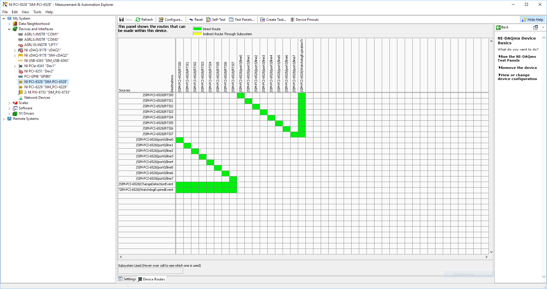
Probably not. Unless the routing plan is in fact reversed as it seems a bit sorta that. As stated on my system, you can route * of * a port of entry * to * RTSI, or you can route * of * RTSI * to * one output port. This does not make much sense to me, but that's what I see:
If the routing card * is * reversed, your only likely workaround without physical wire would be to generate impulses in question of port 3. It's pretty clear that 1,2,4,5-tetrachlorobenzene ports have no ability to interact with the bus timing, physical wiring would be the only option.
-Kevin P
-
While with PXI-5122 digitizer loop counter
Hello world
I am a beginner of products NOR. Currently I use the PXI-5122, 2014 Labview for the ultrasonic signals. I have a problem when you count the number of signals using an external trigger (by a function generator) source. When I trigger the digitizer under 50 Hz, the meter is working properly (a single trigger = a signal). With a frequency greater than 50 Hz of trigger, the meter is malfunctioning. For example, with the shutter to 50 Hz and 500 number of signals, the counter takes 10s to get data. But, with the trigger of 100 Hz and 500 number of signals, the acquisition time was always around 10 s.
You can see the code in the file attachment.Please let me know if you have any suggestions or recommendations for my situation, I would appriciate that.
Thanks in advance!
Best regards
YouWorldALoneMe,
Looking at your code, you're software re - trigger your device. With your Setup, you configure the digitizer to hold a single record acquisition in your "A - Scan.vi". This VI opens the resource OR-SCOPE, configure, captures, returns the data, then closes the resource OR-SCOPE. It then does this for each unique A-Scan that you do and would be the reason that b Scan.vi takes so long. It appears then that fewer than 50 Hz, this reset any software and reconfiguration and the acquisition can occur without missing a trigger, but more than that, your triggers occur faster it takes to do these things.
What you need to do set up the digitizer to a multi-record acquisition. This is done using the 'niSCope configure horizontal timing.vi' and wiring in a number higher than '1' in the entry "number of records". "You can find an example of how to perform a multi-record acquisition if you open the Finder of example OR > material input and output > Modular Instruments > NOR-SCOPE > Getting Started > niScope EX Multi Record.vi.
In this example, the digitizer is only once configured, and it returns all the documents requested at the same time. For your application, each record would be a simple Scan of A, and then if you configure 500 files, your B-Scan would be 500 wide. This time allows the material to rearm between triggers that is much faster to do it in software.
For a verification of more complex example out (in the finder of the example) "niScope EX Multi record go get more available Memory.vi"
Kind regards
Nathan P.
-
Extract and save all the channels of the PXI-5105 with 4 M of edge detection... Help!
Dear collegaues!
Please help me to improve my request, exhibit attached and sorry for my English.
So my task is to extract and save all the channels (eight) of the PXI-5105 with 4 M of detection of peaks and sample rate 4 M with loop 1 sec...
Entered all my channels are wiring detectors NaI with 0, 5... 1 microsec pulse (really) width and 0 kHz at not more than 40 kHz freq.
Why I chose the registration of 4 M and the sampling frequency of 4 M namely? Answer is that I tested previously PXI-5105 40 kHz generator and pulse width 0.5 microsec. It works great and detection of peaks indicate 40000 pulses/s for me. If I set lower than 4M record and sample rate of 4 M, it is without work. In my honest opinion record 4 M and the frequency of sampling of 4 M are parameters very min.
In the detection of peaks time present only 6 working channels... When I connected to diagram more 6 "detector.vi peak" - I see the error "...". out of memory... ».
Advise me please, what needs to be done to it, it's all working well.
-
PXI-5421 Signal routing to PFI4 and PFI5
Hello
I am trying to route bits 0 and 1 of a waveform I generated using a PXI-5421 AWG group work PFI5 and PFI4 respectively for the ports. What seems to happen, this is the first installation is written the second set so that only one PFI port is set up. I've attached a screenshot of a section of the configuration of the VI. Can two bits of a waveform being routed to two ports separated the IFP at the same time?
Thank you
Steve
Hi Steve,.
Yes. There is data on the PXI-5421 4 markers, and each can be configured with unique values for each of the attributes of data marker. To set up the markers of data independently, you must specify a 'Active Channel' for the polarity of marker data and number of bits attributes. So in your example, you would just need to add an entry "Active Channel" on your property node above the attributes of marker of both data and wiring in the "datamarker0" to set up the first brand of data and the "datamarker1" for the second. "NiFgen waveform Arb marker" shows how to do this. Do not wire the active channel range cause really all markers 4 data to configure when the value of each attribute of data marker.
Hope that helps.
-
Is it possible to route signals of relaxation between two chassis PXI-1002 with the PXI-8335?
Hello
as the subject says, I am interested in the delivery of a signal to trigger between two chassis PXI-1002. At present, these two chassis are connected by a MXI - 3 system using maps PXI-8335. The software is Labview 2010 sp1 and 380 NIScope drivers.
We want to keep (a PXI-5122 by chassis) scanners supply separated due to the requirements of our measure! The chassis are connected via cable to fiber optic. This explains why I can not just use the shutter release in Star, or connect via 'Trigger' or 'clk' cards (the inputs / outputs to the front of the cards).
I found a few examples, but they seem to all be designed for use with a chassis only, I'll call later to the examples that inspired me to this point. Each guide explaining the synchronization of several chassis systems seems to use another material or VI is not accesible to me. This makes me wonder if my hardware has the capacibilities I need.
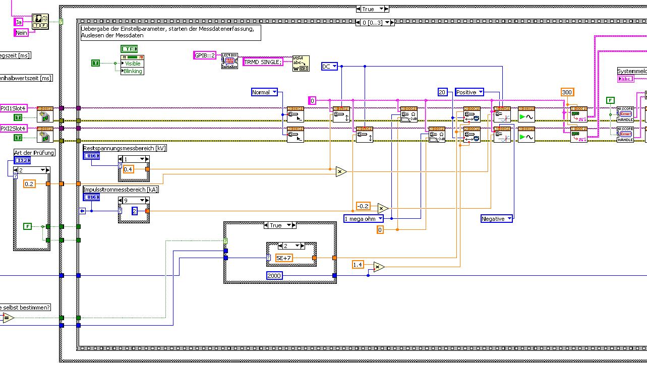
The first picture shows approximately where I started from (sorry I can't post VI, confidential...):
Only the middle part is interesting. Two sessions are initialized and manipulated parallel, trigger too. This has led to delays in the signals and should now be fixed. This apart from the VI works fine.
Goal is to trigger only on one channel but both devices! If possible, the device will trigger must be chooseable.
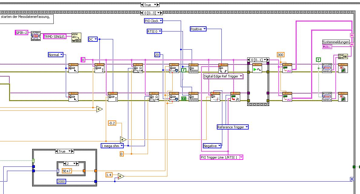
I started to rebuild the VI using the "EX Synchronization.vi 5xxx niScope' seeming spontaneity. The result is shown in the following image:
I tried different RTSI lines, but had no positive results. only the main channel has triggered.
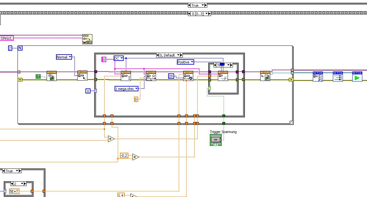
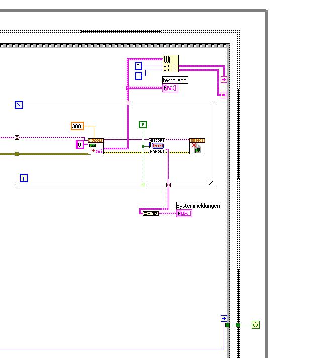
After this first approach, I looked in the "niScope EX .vi multi-Device configured Acquisition (TClk)" and other examples of TClk which seem to work for similar problems. The VI of reconstruction can be seen in the following images:
(Sorry, I had to use two photos..)
In this case, I didn't have no choice for trigger lines, it would automatically set the VI TClk. I tried to trigger on both devices, though. This second approach seemed promising to me, but it was an error:
"niTClk Synchronize.vi:1".
Index (starting at zero) of the session: 1
The error reported by the pilot of the instrument:
No registered trigger could be found between the
devices on the route.If you have a PXI chassis, the chassis correctly identify in
MAX and make sure that it has been configured correctly. If you use PCI
devices, make sure they are connected with a RTSI cable and that the cable RTSI
is saved to the MAX. Otherwise, make sure that there is an available trigger line
the trigger bus shared between devices.Source device: PXI1Slot4
Target unit: PXI2Slot4
Status code:-89125niTClk Synchronize.vi:1
Index (starting at zero) of the session: 1
The error reported by the pilot of the instrument:
No registered trigger could be found between the
devices on the route.If you have a PXI chassis, the chassis correctly identify in
MAX and make sure that it has been configured correctly. If you use PCI
devices, make sure they are connected with a RTSI cable and that the cable RTSI
is saved to the MAX. Otherwise, make sure that there is an available trigger line
the trigger bus shared between devices.Source device: PXI1Slot4
Target unit: PXI2Slot4
"Status code:-89125"
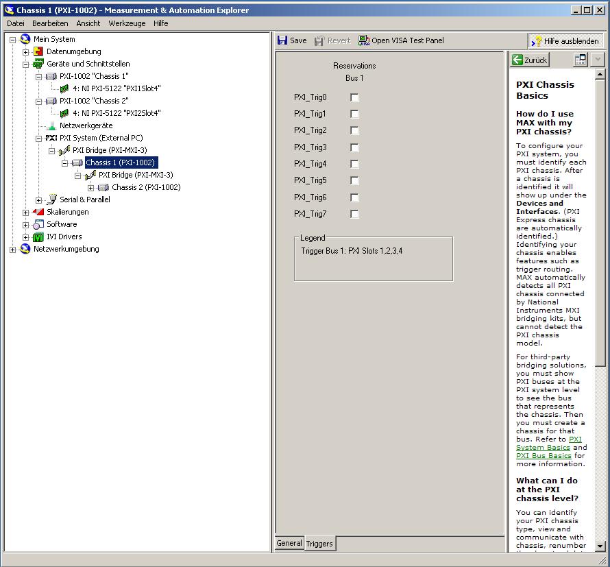
This error came back even after I've identified this drug as possible to the MAX, as shown in the screenshot:
In some of the textbooks, they showed how to get the MAX trigger lines, but as you can see, there is only booking options in my MAX. Whatever I do, I can't find options to define how to get my trigger signals...
In principle, it is possible to trigger instruments in different chassis, which is indicated in this Guide and others... the question that remains is can it be done with my set of components?
I understand that the use of multichassis compromised the integrity of the lines very adjusted as trigger in Star etc., so the configuration should be taken into account in some way, that my approach does not, I knew... But there must be a way to do this? And to start: to get just any signal from one device to the other trigger!
For any advice on this issue, I would be very thanfull!
Concerning
Max1744
Hi Max,.
Thanks for the detailed post and explanations of your application and requirements. You're right using TClk, because this is the optimal method to synchronize the 5122 digitizers. The original VI you worked with is unique for some of the legacy scanners and does not directly work with scanners based on the most recent CMS (for example the 5122). The good news is that you can synchronize these cards to separate chassis, but it will use the calendar 66xx and synchronization (T & S) cards in the chassis of the master and the slave, as indicated in the guide that you have accessed. These are needed because a common reference clock must be shared between them as well as a couple of tripping. MXI itself can not handle export triggers and clocks, so there is no way to do this without physically wiring between the chassis with cards T & S. Unfortunately, regardless of what specific method, you use for synchronization, it will take a material extra beyond what you currently have.
As one of your needs looks like it is necessary to retain wiring between the chassis directly, you may need to consider to synchronize using 1588 or GPS protocols. 1588 Protocol is a system for synchronization on the network while GPS course use antennas and locks for a common wireless signal. Although these synchronization methods may allow you to keep your chassis isolated, they will also require some manual configuration because you would be able to use the TClk synchronization and so the level of synchronization you can get between the cards may not be as good that can physically wire signals between the chassis using T & S cards.
Hope this helps,
-
Degraded signal: PXI-2501 1 wire 48 x 1 w / TB-2605
Dear friends,
I have a PXI-2501 configured in 1-wire 48 x 1 w / a TB-2605 terminal block. My goal is to move analog square waves generated with a PXI-6259 to a Bank of several LEDS. Last week I posted a question about the wiring of the TB-2605 and wired my block according to the jpg (attached below), I received. Unfortunately I'm having a degraded signal once routed through the switch... Very dark LEDs as opposed to very bright cases, I connect directly to the channel of the PXI-6259 AO. My first thought is that there is a bad connection GND somewhere in my wiring. However, before you disconnect the wires and hunt this grimlin with the voltmeter, I would like some consensus of the other members on the diagram below. I'm wired up properly?
Thank you
Zach
Hello Zach,
What features of the PXI-2501 make it suitable for your application? Have you considered using a different switch? The PXI-2503 has the same 48 x 1 1-wire topology and can be used with the TB-2605 terminal block. It's spec'd path resistance is < 1="" ohm="" and="" bandwidth="" is=""> 10 MHz. The PXI-2503 using electromechanical relays, so this module has a life expectancy over relay and a rate of slower cycle compared with the PXI-2501.
The PXI-2503 might work best for your application?
Chad Erickson
Switch Product Support Engineer
NOR - USA
Maybe you are looking for
-
Back to the same place of the web page
When I click on the arrow to the left happens to me on web page, I was ahead, but there also go to the top of the page, but not to the task, I was working, so I have to scroll down to this place. How can I get back to this place on the web page?
-
From time to time the body of my messages in my Inbox is "scrambled", which means that the messages all resemble http code and cannot be read. And code in one does not necessarily match the message - inside can refer to a different message. It occurs
-
I can't get a site to print an entire page. on the right side is cut off.
The page is too large in width. I tried to 'fit to page' but nothing helped.
-
Human resources and GPS info collected
Hello Is it me, or there is no fitness application that can capture HR and GPS to be collected and reviewed online? I understand that native watch OS 2.0 applications now have the ability to read the data of the health package, including human resour
-
Salvation; I have 2 vectors of 2 dimensions of each of them, and I take the element x, j of the vector (2D) first and the element x, j of the second vector (2D) to another. I have not found a component to work with this 2D vector, someone has an idea