With the help of control and simulation module; e to get the time the MISO model Manager
Hello
Please can someone show me how to find the response time of the system below using the module control and simulation?
(y (k) - 1,7407 y (k-1) + 0.6236y (k-2) + 0.1782y (k-3)) =-0.0932 u(k-1) + e (k)
where there is out, u came and e is a white noise.
I tried to enter the CD construct MIMO model, then connect it to CD response time. * s vi.
But what I really need to enter the model coeffs every time? and I still don't see the answer!
Help, please...
Kind regards
ruser
Hello
you have the correct image... I used the Toolbox ID sys (Assistant)... to estimate the system model...
and I tried all week last get the model of my system in labview for use the control on this module.
Alhamdulillah...
I ended up doing... I saved the template to a file from the Toolbox id sys... (my model is in discrete form) then I loaded it in labview using load file pattern...
so now I in labview...
now for control parts...  ..
..
Thank you again...
ruser.
Tags: NI Software
Similar Questions
-
control and simulation Module spring mass
I'm using Labview 2010, and tasked the simulation module (just 15 days before the date of expiry. trying to see if the program will work before I spend $4 K) and try to calculate the dynamic response of a spring index.
I was able to complete the program in the simulation section (I think). I now need to feed a sign of acceleration in the module which I have already captured at a sampling rate of 100 k/s.
Test technician said I should add 500 ms from zero to the front of the track to make sure that the system is stable before the trace of acceteration of power is in the simulation module. I have alreay done reading and adding zeros to the chain.
I can't feed the trace in the module control and simulation.
The engineer said he was able to do the math in MatLab and simulink (I think), because I have not used this program and we do not have a copy I am doing it in LabView.
In addition, I would add that this forum is blocked by my firewall to work.
If you need more information, I'll have to return to work and get it.
-
External template function (control and Simulation Module) on Linux using target
Hello
I am trying to run the 'EMI_Integrator.vi' for example on one OR cRIO-9024 (nor a myRIO).
I moved the file 'EMI_Integrator.so' to the ' / or-rt/system ' on the cRIO and the .so file added to the target in the LabVIEW project. I can not navigate to the .so file directly so I specified the .so path manually, but the VI is not able to run and an error of-2366 'reissue model '.
"You can find the original version of VI in the Finder for example OR", but I've included my modified version that has a LabVIEW project and targets already loading.
Thank you
Mitch
Hello Mitch,
If you want to use the external model on a 9024 node, you must copy the appropriate VxWorks library (.out) file to the/or-rt/system folder of the target. The .out file is located in LabVIEW\Examples\Control and Simulation\Simulation\External model Interface\EMI_Integrator\RT-Lib\vxworks.
In LabVIEW, have the external model node refer to the file of the library appropriate for your operating system. In my case, I use a .dll for Windows file located in the folder EMI_Integrator, above.
When I run the VI on the cRIO target, referring to the library on my host computer, it will automatically search the folder to/or-rt/system for a file with the same name with .out.
Kind regards
-
Discreet Integrator (control and Simulation Module) - LabVIEW 2015
Hey everybody,
I'm trying to drag the discreet Integrator on a block in 2015 of LabVIEW diagram. All other vi in the "range of discrete linear systems are draggable, but not the"discreet"Integrator." I noticed the same thing for the continuous Linear Systems Integrator. Anyone explain how to solve this problem?
Sincerely,
Lex
Lexicondi,
Unfortunately, these functions cannot be moved out of the loop control & Simulation. We support only discrete transfer, of State spaces and ZPK models function.
So, if you want the "discreet Integrator" outside of the SIM card, you have the following options:
one) to use the "discreet transfer function" as T /(z-1) (or any other type of discretization available in discreet Design continuous monitoring);
(b) you can develop your functions inside the control and the Simulation loop and then create a subsystem of her. The subsystem can move outside the SIM card also. Here, you can use any SIM function you want;
I hope that this should be sufficient for your application.
-
Control and Simulation in a loop / while loop with TCP/IP reading / writing of synchronization
Hello, I have a problem with reading TCP/IP and written in two loops. The problem is NOT to get the two loops to read and write to and from the other. This has been accomplished. My problem is when I run control and the loop simulation on my laptop and the while on a RTOS remote on the controller on-Board of LabVIEW in a remote PXI chassis, the while loop the remote system running on four 4 times faster than the loop control and simulation on my laptop. In other words, for each iteration of the loop control and simulation on my laptop, there are 4 four iterations of the while loop on the remote system. I need to know how to get a degree of kinship (1:1) with these iterations of the loop. When I run a longer simulation in real time, say 10 seconds, the control and Simulation loop begins to slow, i.e. the simulation time slows down until it is no longer in real time and the "Late Finish"? Parameter is set to true and the LED lights and continues to stay lit. At this point, the system destabilizes due to what I believe is being well sampling rate too discreet and I have to end the simulation. How can I get a ratio of one to one between the loops and also to avoid slowing the loops causing destabilization?
To give an overview of my application, I implement a control system in a network, seen in "image2.png". This is achieved using my laptop as a subsystem 1. Reference signals are generated from the laptop and the error signal is produced. Control measures taken and the control signals are sent via TCP/IP to the remote system. Position feedback is returned, and the process repeats. My system has Core I7 Procs w / 3 GB of RAM, up to 1 GB/s speed via ethernet and LabVIEW 2011 installed with all necessary modules and networking tools. The attached VI Custom_Wireless_Controller works on my laptop. The remote system I'm working on that has the 7830 NI R Series with FPGA card. OTN runs on the PXI chassis with an enbedded controller that has networking capabilities of up to 100 MB/s via ethernet. I use the FPGA for the acquisition of data and apply control signals to my plant. The plant is the PCE twist connected to the FPGA through the cable of the ECP - RIO of NOR. Subsystem 2 is this side of the CNE. The FPGA collects position, he sends to the controller via the network, receives signals from the network drive and writes signals to the plant power amplifier that operates the plant. This process is repeated and the VI and is titled Custom_Wireless_Plant.
I appreciate the help really and look forward for her and for any question!
Well, the first step is to understand what you have set up right now. Your control and Simulation loop on the side of the controller is configured as 'Runga Kutta 4' and you have a loop timed on the other side. In addition, you have the primitives of TCP/IP on the control and the Simulation diagram and means he will perform (a message) on the size of each minor step, which in your case is 4.
So, you have two options:
1. replace the Solver side controller Runga Kutta 1 (this must synchronize loops)
2. hold RK 4, but create a Subvi around two primitives of TCP/IP and configure from the VI to run than the major (continuous) step-size. If you do it right, you should see a 'C' on the upper right part of the VI you have created.
Please let me know if what I said is not clear...
-
loop control and simulation: sync settings
Hello
Is it possible to access times higher at 1 kHz source in synchronization settings, control and Simulation in a loop, without use of real-time targets? For example, using time cpu.
I use myDAQ OR data acquisition, and I need a 100 kHz synchronization source about.
Thank you very much.
Kind regards
Keshav
N ° when running on a PC of the class, you are working with a set of standard material (with its clock 1 kHz) and a non-deterministic BONE, and there is nothing you can do about it. That is why acquisition cards NOR are all smart devices with their own processors, memory, and clocks.
Mike...
-
Problem control and Simulation
I worked in the module of control and simulation of NI Labview 2013 and created a VI as indicated in the attached file, but I don't understand the output of VI.
I applied a progressive input signal to device to transfer function = 1 /(s+1) and the desired output (exp (-t)) appears in green color (drawn by me in MSPaint) but it displays the output as one shown in red color.
As the inverse of 1 /(s+1) Laplace = exp (-t), the graph must be a value of 0.3678 at t = 1 and 0 to t--> infinite but the (red) output is exactly opposite.
Can someone explain please exit this is why it is like that?
Concerning
When you apply a step response, you must multiply your transfer function of 1/s to account for the progressive input signal before making the transformation from Laplace to get the correct result. In your case, the transformation gives: (1 - e ^ (-t))
There are many explanations of answers online, but here's onestep.
-
How can I extract a part of a signal inside a loop control and simulation?
I would like to extract the part of my signal between 0 and 3 seconds. I tried to use the extract of Portion of Signal VI Express, but it does not work. I'm setting the length to the offset 0 and 3 seconds. However, nothing is displayed in the output. I used this before VI successfully, but it wasn't in a loop control and simulation. Is there something special I need to do to make this work properly in this case?
This forum shows how to measure the time between the Digital pulse http://forums.ni.com/t5/LabVIEW/Measuring-time-between-digital-pulses/td-p/1056881
In addition, it would be a good link https://decibel.ni.com/content/docs/DOC-12160
-
I replace my airport express with the new model. Flashing orange. It works, but cannot configure security. Tried to reset via the reset button. Tried unplugging and tried unplugging the modem. I would like to fix.
Modem... doing and... model number you have?
What operating system do you use on your Mac, or you are using an iPhone or iPad set things up... or a PC?
-
Sometimes when I start my PC I have a black screen with the Windows boot manager at the top. Although there are several options available, that nothing happens no matter what keys I hit and the only option is to shut down the computer and restart completely. Sometimes the Boot Manager page turns and my office sometimes opens fine. I've updated with everything Microsoft has Windows Vista and I still get this screen. Anyone has any ideas.
Do a startup repair and see if that fixes it:
Download the ISO on the link provided and make a record of repair time it starts.
Go to your Bios/Setup, or the Boot Menu at startup and change the Boot order to make the DVD/CD drive 1st in the boot order, then reboot with the disk in the drive.
At the startup/power on you should see at the bottom of the screen either F2 or DELETE, go to Setup/Bios or F12 for the Boot Menu.
When you have changed that, insert the Bootable disk you did in the drive and reboot.
http://www.bleepingcomputer.com/tutorials/tutorial148.html
Link above shows what the process looks like and a manual, it load the repair options.
NeoSmart containing the content of the Windows Vista DVD 'Recovery Centre', as we refer to him. It cannot be used to install or reinstall Windows Vista, and is just a Windows PE interface to recovering your PC. Technically, we could re-create this installation with downloadable media media freely from Microsoft (namely the Microsoft WAIK, several gigabyte download); but it is pretty darn decent of Microsoft to present Windows users who might not be able to create such a thing on their own.
Read all the info on the website on how to create and use:
http://NeoSmart.net/blog/2008/Windows-Vista-recovery-disc-download/
ISO Burner: http://www.snapfiles.com/get/active-isoburner.html
It's a very good Vista startup repair disk.
You can do a system restart tool, system, etc it restore.
It is NOT a disc of resettlement.
And the 32-bit is what normally comes on a computer, unless 64-bit.
See you soon.
Mick Murphy - Microsoft partner
-
problems with the adobe application manager
I have problems with the adobe Application Manager.
Please see the links below.
- Does not open App | Wheels of progress turn continuously
- Creative Cloud Desktop App taped blue spinning wheel after update.
Hope this will help you.
Kind regards
Hervé Khare
-
Is it possible to record "Mozilla Persona" - password with the FF password manager?
Is it possible to record "Mozilla Persona" - password with the FF password manager?
Thank you
polltiPersona.org or login.persona.org is present in your Exceptions list?
-
Function of memory in the loop control and Simulation - problem of the ODE Solver
Hello
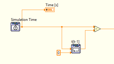
I'm correctly using the control loop & simulation to simulate the behavior of what is essentially a shock absorber-spring-mass system. In the process of change in time (dt) is used to integrate an arbitrary value. I use a rack depending on memory to store the time, to calculate the change of time (dt).
The simulation is quite complex, because of the precision required, not all the ODE solvers can all support. Currently I use the Adams-Moulton method, this works very well for the simulation. However, it cannot detect the change in time, the change is constantly zero. This problem has auto market by using an another ODE Solver, but then the simulation has been messed up instead (even when I listen to the step sizes and tolerances). So I'm pretty confident that Adams-Moulton is one of solver ODE best suited to the problem at hand.
Is there another way to store the previous hour and use it calculate lag, that the use of the memory function? Everyone knows about these problems before?
I did a lot of research of error using the probe, but I'm sure that there is a problem with the ODE Solver and memory function. See the image below, showing basic how is calculated the change in time.
I'm pretty new to LabVIEW, so if there is something else I missed I would be happy to hear it.
PS! I set the tolerance minimum step of size/relative and absolute for the Adams-Moulton to simulate the behavior of the system properly.
Problem solved!
It turns out that the ODE Solver has struggled because of two "table 2D find" used functions. This was created for the interpolation/extrapolation, which caused a problem constantly and the ODE Solver could not resolve correctly, so the functions of memory doesn't work does not correctly or the other.
By increasing the table manually, I could use closest method instead, with also good results as interpolation.
-
I use RoboHelp 9 with WebHelp output.
I have five outings, which one contains help for common functions, while the other four contain help for modules under license. When a user opens a module under license assistance, the user sees the soul help and authorized assistance. In addition, the files are conditionalized so that the unauthorized search a help licensed module brings nothing.
I have been solving problems with the previous topic and the next topic which, thanks William, I learned are associated with browse sequences. After having tried various configurations, I have a few questions:
- HR support a sequence to travel alone in a project, even when the project has several outputs & fakes?
- If HR supports a sequence to browse only, does that mean that there is no way to create a unique navigation for each separate output sequence?
- If HR supports several sequences of travel, which is the workflow?
I also maintain a table of 'master' contents which contains all the modules, frequent and without a license. What I've done for now is to autocreate a browse sequence based on the table of contents "master." When I generate the output of a module under license, which is conditionalized, I only see the table of contents for this module and, therefore, can only travel between books and subbooks for this add-on. I also checked that the subjects that do not appear in the module conditionalized as for another module licensed, do not appear in the list of search results either.
Carol
Me again, Carol
You also questions about the functional differences between WebHelp and WebHelp Pro, so let me explain.
I know only two major differences other than (the additional benefits of analytical feedback reports) and the management of 'Zones' with authentication in RoboHelp Server.
- The behavior of browse sequences as explained above
- The fact that the categories of content are not supported in WebHelp Pro for this latest version 9.
In regards to sequences to browse you try to anticipate the various modules (licensed, etc.): multiple browse sequences are included in an single . File BRS. Sequences are defined in the XML code in the single file.
As a solution (for WebHelp and WebHelp Pro), you could create a Help.brs of the NPM. that you have already created a module; then backup and archive. Then create a change for the different module before generating again. The Help.brs of the NPM. will need to have the same name as your project, so you will have to manage the .brs desired file in the project folder when you build this version. All your other choices (table of contents, Index, conditional tags, etc) remains the same for the respective modules.
Finally, I notice that you generate apparently WebHelp Pro right now even if you are not published on the server of HR? This is really not the best practice. You must generate WebHelp plain for a web server that has no HR server on it (even if you can be getting away with it). Regarding your concern about "breaking" something; each output is placed in another! SSL! folder automatically when you build, so you should be able to generate WebHelp without interfering with the release of WebHelp Pro. Then, you can republish on the HR using WebHelp Pro Server, whenever the server is ready.
John Daigle
Adobe Certified RoboHelp and Captivate instructor
Evergreen, Colorado
-
Control and simulation and data acquisition
Hello
I am applying to motor control in Labview. I'm sampling speed from DC engine in real time through an acquisition of data. (my sampling time is 1000 samples per second)
Then wrap speed as input to a Simulation (simulation and design of the order) and inside the loop simulation, I have a PID controller. The PID has the actual speed of the engine for the acquisition of data and the engine reference speed as input.
Reference engine speed comes from the generator of signals (control design and simulation-Simulation) and is a waveform.
My step in the engine size is 1000.
I am running this application real-time and drawing the reference signal and the motor real signals. I run into several problems with regard to the calendar.
1. when I change the size of the step of the simulation loop, the frequency of squares of reference also seems to change. For example. What step size = 1000, duration of pulse = 1 s. What step size = 100, pulse width = 0.1. (My pulse frequency is 1 Hz, Simulation clock - 10 kHz). How step size can affect the pulse width.
2. can you explain the relationship between the DAQ, the Simulation step size loop sampling time, Loop Simulation period.
3. If I want to collect different sets of data using sampling different hours, it's OK to change the sampling DAQ time without changing the size of the step of the simulation.
Would also like to emphasize that the DAQmx calendar under sample clock mode is placed in front of the simulation loop and the output is connected to the loop simulation.
Appreciate any help.
Hello
Maybe some screenshots of your code would help. Furthermore, what you have read your samples together with your DAQ screws?
(1) If you have a waveform, the output is specified as:
For example, if you change the size of the step of the simulation loop, you change the simulation time which are introduced into the signal generator and affecting the waveform that you see if you do not have a size quite small step to characterize the waveform that you generate.
(2) sampling DAQ rate is the speed at which samples are taken on the acquisition of card data itself. The size of the simulation step, help. "Specifies the interval between the time when the ODE Solver evaluates the model and updates the results of the model, in a few seconds." Simulation loop, still using, "Indicates the amount of time that elapses between two subsequent iterations of the loop of control & Simulation.". " "Step size determine the value of t that is introduced to the functions you use in the loop simulation while the loop simulation period controls simply to how fast you change the following t value. The sampling rate of DAQ hardware is a clock of completely separate hardware controlling the analogue-digital on the DAQ card converter so that you can get a deterministic dt between the samples being acquired.
(3) you can change the schedule for the acquisition of data, but you will need to restart each time the changes take effect. If you change the calendar of data acquisition and want your values to correlate with your simulation, you will need to change your size of step as well.
-Zach
-Zach

Maybe you are looking for
-
Cannot show the contents of the message when searching for local folders
Using Thunderbird version 38.2.0 I have recently moved most of my emails from our server to a 'Local Folders' directory to free up space on the server. Using the Thunderbird global search feature (top right), I can see the emails (subject lines, of /
-
Coordinate the functions of Boolean values by their name
Hi all I have somewhat a challenge I appreciate some help with. I am trying to create a program that synchronizes the function of a group of Boolean values by their names. If the Boolean values are names bool 1_i, I want that they be synchronized suc
-
CQ61-105ed (IDT 111:7608 subsys 103C 3069 d) audio drivers
Hello Just try to get your hands on a driver for the Compaq CQ61-105ed audiochip for Windows XP. I tried tons of files and drivers, even forced a couple, even if they were not intended for it (closest to you I had was a subsys d 111:7068 103C 3064 dr
-
SP 3 installation error message: "file not found and the installation is stopped.
Original title: Setup servicepack3 error received message error servicepack3 file installation will be locater and installation is stopped
-
(Help) Need to Code Simple to print "Printer Bluetooth Blue Bamboo"
Hi masters, I need sample code for printing in Bluetooth printer BAMBOO BLUE, thank you for all