Custom control with look system visa
Hello, I would like to have control of Visa's resource name with the same look like a ring system. See the file attached what I mean. I'm not sure how to work with the customization tool, I need some advice.
Is there any library on the web with xcontrols and custom controls?
Kind regards
Jimmy
Would the .ctl I have attached to this workstation for you?
Control of NI-VISA for Style XP
Tags: NI Software
Similar Questions
-
Custom control with couple or the input voltage system
Hello
I'm relatively new to LabVIEW and this is the first time that I'll use for an application of movement. I have a controller/chassis cRIO-9074 with a few modules NI 9514 IO, servo motors and drives, and I'm trying to do is to use a custom control in my system (a sliding mode control law) to generate the signal for the movement of the engines. I was able to produce a movement OR softmotion but so far I've been able to produce with position, speed and acceleration as inputs and to optimize PID gains. What I want to do is to send commands to torque or tension from the entrance of my right to command control is torque for motors. What I was wondering is if it's possible with the components that I use now and if someone could direct me to useful articles or books that can help me.
Sorry if is a noobie question but I only worked theoretically with systems of control far and I didn't simulate the results with matlab before that. It is the first time that I had to get the experimental results to validate my proposed control right. Thanks in advance.
Hi,.
This may be possible, but since sending the commands of torque or tension directly don't are not supported in scan mode, you can use your 9514 FPGA mode.
This link describes the components needed to run the FPGA device.
You should be able to find examples in the Finder for example NEITHER, but here is an overview of the use of FPGA that can be useful as well.
-
custom control with the mask of the image
Hello
I am trying to create a custom control that looks like a bulb. I want to do is have a picture of a light bulb with a Boolean flag behind it so when you press a button the light bulb gets dimmer or brighter. I know how to customize the controls and can change the color of the Boolean indicator but have no idea how to do it. Any help would be grateful.
See you soon
James
GIF will allow transparency. This will show through the image.
Also, few throughts. Change the box color instead of a Boolean, this event will allow you to change just the color instead of use the Boolean color via a property node.
Another easy method is to use a ring to the bottom of the picture load the image of your bulb, fill the bulb with several shades (May 16) brightness, then import the sequence into an image control, then you will have multiple shades you can view any required customizations.
-
Hi all
I would like to create a button custom as a master, so that if I change the look of the master all other buttons are changed.
I did it with a custom control, such as a 'type strict def' otherwise the look will change , BUT if I do this as a strict type def I can't change the Boolean text more which should be different on each button.
How to create a master control of a button where the look apply to everyone else but not the Boolean text?
Steve Chandler wrote:
I don't think that you can do. I just looked and as I suspected the Boolean property text is read only for strict typedefs, you cannot use the nodes property to change the text.
As a just solution make it a typedef. When you want to change the open look the typedef and strict rendering, make your changes, then make no strict again. You will need to update the text Boolean yet once for all instances. Kind of pain. This is perhaps something for the exchange of ideas.
Alternatively, remove Boolean text and replace with legend
-
When I click on any icon in my control panel, a black window opens and C:WINDOWS\system32\rundll32.exe is what's wrong with the system
{Assuming the rundll32.exe file is not found}
See if them can restore the file rundll32.exe:
http://support.Microsoft.com/kb/812340 Ramesh Srinivasan, Microsoft MVP [Windows Desktop Experience] -
Hi guys,.
I use labview to control test, but normally predispose the user interface as a windows with buttons, indicators, graphic controls program etc...
But "they" want to be a process diagram that can be used to control and monitor the user interface stuff. Fine. However, I created custom controls by changing true/false images on radio buttons.
They work great when the program currently does not work, IE real gives an image, click on it and the image changes, great. But when I run the software as soon as I move my mouse over the control, on what it shows default image for example a radio button, if I click and then move the mouse, it shows the picture its supposed to, but how can I stop it showing the radio button on a mouse?
See the attached images.
Thanks, Zac
You can find a great video tutorial on how to create a system of buttons on the forums of JKI. For your particular purpose, you might want to look at the DSC Module, which has the commands you seem to be wanting to use.
-
How to turn RT FIFO on a shared variable for custom control
I try to get my shared variables behave: update when I tell them of and only update once. It's the sort of 2 separate problems. Update only once should be fixed by activating RT FIFO on the shared variable. However, if you create a shared variable by using a custom control (because your data type is not available on the menu drop-down), allowing RT FIFO is not available. Why is this? Will there be an another GUARANTEED way to do this?
Description of my goal: after having many problems with a large scale of my real-time program version, I started from scratch. My program is that the bases in order to send a signal to my goal of running on a few D/A channels, then return the data that I read A/D channels to ensure that the waveform has the same appearance. In addition, the program should be able to repeat this process without having to reboot.
-Host is a state machine with: initialize - reset variable, check that the UI events - start target, target stop and end program, send data - to create 2 waveforms and send it to the target using the variable "data entry" (table 2D-double), data Get shared - read the entire waveform on the different channels after it ran using the shared variable "all data output" (table 2D-double) , Write to the file - (does nothing), stop - program ends.
-Target is a loop with 2 States inside: false - target does nothing as he waits to be the host to say 'Start', True - target Gets the shared variable input data, runs on 2 D/A channels and reads the equivalent A/D channels to make sure the waveform actually ran as expected. This happens in a deterministic loop with a non-deterministic loop waiting for the command "Stop" on the host. After the written entry, the D/A signals stop and playback of signals/a. are placed in a 2D array and sent to the host via a variable shared, "all the output data".
-J' tried to put "all the data output" in a while loop which must reiterate if he does not obtain data in the specified time-out period. I also removed the while loop but kept the specified time-out period. In both cases, data are collected twice!
-Without specifying a time-out, the host never gets data updates "all output data" before he goes into another State.
Summary: I need update they once when I asked to a my shared variables. I think that my program is about as simple as you can get, so I'm surprised to see why he is currently not completely reliable.
(I have attached the vi host, target the vi and variable)
Hi FireIce,
To answer your questions:
1 RT FIFOs are supported data types can be pre-allocated space. This is to keep the determinism on the RT system.
2. reading of the variable in the loop and have the chart outside the while loop will only show the last value of the shared variable, showing actually only a single reading. Then if it works for you, it will give the same result.
Looks like you have network buffering enabled on your shared variables. Is this true? Shared variables must always have a value, and so it will continue to contain old data to the new data is written to it. If you have buffering enabled network, new data can be added after the former, which actually look like you read the old data twice before getting the new.
-
Custom control in the new VeriStand workspace
Anyone know if it's possible and how to make the custom to the new UI controls? I have a custom device that creates channels 400 + and I would like to find a way to add them to the user interface without having to manually configure each channel individually.
I have a way for the user to choose if each digital output is discreet, PWM or encoder mode. Currently, they have to drag into individual channels labeled 'Enable channels', 'Output Mode' and either 'Discrete Value,' 'PWM Duty Cycle' & 'Frequency PWM', or 'Encoder quarter' & 'encoder Index Control. " Is it possible to create a custom control that contains Boolean controls and digital necessary? I know that this was possible in the old VeriStand workspace, but I have not found a way to do in the new, as there does not appear to use a directory full of screws for its controls.
Thank you
Mitch
Hi Mitch,
I'm sure that this functionality does not yet exist for the Manager of the user interface, but I guess that NEITHER is likely to know that it is a widely used feature.
When I asked him about this a few months ago, I think the answer is that it must continue to use the workspace controls customized with the workspace and migrate the rest of your features to the UI handler. Once the UI handler and the Worspace may operate at the same time in the same application VeriStand.
Could you describe the feature you're looking for with screenshots?
I hope this helps, but maybe someone of NOR can enlighten us more about it!
-
I'm just starting to use the evaluation copy Veristand to see if it can do what I need it to do. It seems very customizable, and I tried to create controls in the workspace personalized with Labview. I would like to make things like radio buttons, lists and menus in the workspace to control my drop-down model. I have tried everything just by taking one of the digital controls and its replacement by one of the controls mentioned previously, but it gave me an error message saying they were not supported. It seems that I'd be able to do this using the free label template, but I'm not sure how to do this. I was able to find an example of a custom indicator (min/max one), but could not find everything related to custom controls. Are there examples or tutorials, that I could look at? How could I go for some of these controls of Labview in things that I could use the Veristand workspace?
-Eric
Hello Junior, I have some answers for your problem.
1. I have attached a zip file that contains your renamed control and build a project in it. You should be able to unpack, check the construction features and make sure that the output destination is C:\Documents and Settings\All Users\Documents\National Instruments\VeriStand\Display models. Trigger a build on that and you should get EricHettlerSample - Radio.vi and EricHettlerSampleControlSupport.llb in there. Once you have this launch a workspace, you will be able to drop the EricHettlerSample - Radio in the control list control.
2. for the explanation. I think that when you perform a save as on the example of the min - max you download the Web of LabVIEW cross link on the screws that the llb with that of the vi.lib. Do a save as will not work. What works, it is that you create a project and setup a source distribution to generate the custom control. Here are the steps that I have take based on your attached file:
- Rename in windows Explorer, the attached digital indicator - radio.vi to EricHettlerSample - radio.vi
- Open LabVIEW convert the .llb you connected to a directory.
- Create a new project file.
- Radio.vi open EricHettlerSample - under my computer, when LabVIEW invites me to some VI I search in the directory to convert llb. Note that LabVIEW search more files under vi.lib because these are the files that NI VeriStand install labview directory.
- Once I added some of the screws, I mass compile the project.
- Create a source distribution. Add the EricHettlerSample - radio.vi. Go to setting source file main vi for the folder models and all otherwise go to a folder of llb.
- Trigger the build, LabVIEW will do a better job in creating an isolated component which is properly connected.
In General, you always want to create a project to create a custom, control given that Save As not always worked with the LabVIEW VI link in NI VeriStand.
To create a completely custom control project base what you do is:
- Copy C:\Documents and Settings\All Users\Documents\National Instruments\VeriStand\Display Templates\Decoration - free Label.vi in Explorer windows in a directory of your choice.
- Make a change of name on VI in Windows Explorer.
- Open LabVIEW to create new project add the renamed VI in my computer. This will create an empty project to customize the custom controls.
I hope this helps, let me know if it still does not for you.
Also if you still embarrassed by the error messages appears so you will want to clean directory C:\Documents and Settings\All Users\Documents\National Instruments\VeriStand\Screens this directory being where NEITHER VeriStand puts all the controls that you drop into the workspace cache. So if you have a control that cannot be loaded remove all screws in this directory should remove the wrong screws.
-
Configurable custom control of reference for NI VeriStand
I'm working on an application of VeriStand where I'm modeling more than 100 pieces of similar material, each demanding a set of controls and indicators on the VeriStand workspace. Because I have a few hundreds of orders and total indicators to configure VeriStand workspace, it was recommended to me that I should look at using reference varied Custom Control (http://zone.ni.com/devzone/cda/tut/p/id/11123), which is much more efficient to configure.
The main problem I have with varied Custom Control reference is that when it is configured on the workspace, the full channel path appears in the legend next to the indicator/control form. As I have a simulation model complex faily using several levels of submodules, the complete track path is very long (for example. ("Controller/Simulation models/models/CCH_v1_0_bad/Inports/Islington 220kV Bus EAD/CB668/host_close") and tend to clutter the workspace and also make the workspace very ugly looking (more space is used to display the text of the legend that occupied by buttons/lights).
Is there an easy way to remove traces of full path display, while allowing the user to verify the path full path required by say, right click on the object? Or at least it is possible to display one or two levels of the path of the canal, rather than the full path?
Thank you for your attention.
What do you think makes a lot of sense. To do this, you will need to modify the source code of LabVIEW and recompile (build) the proposed model to screen with the right mouse button. You need LabVIEW 2009 for this.
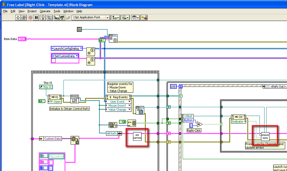
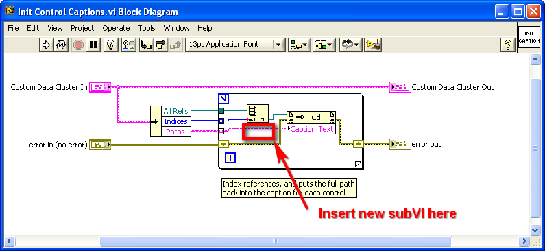
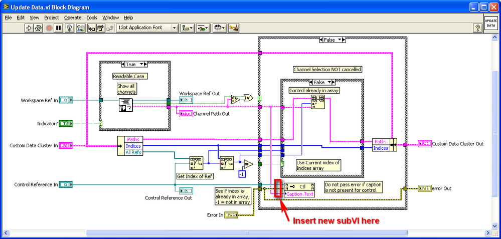
The text of the legend is set to 2 different places in the right-click main-model VI: Init control legends VI and VI of data update. They are presented below:
You need to change both of these screws to do some string manipulation to cut parts of the path that you don't want until it is written in the Caption.Text property node.
I recommend creating a Subvi, which makes the string manipulation, in this way you can insert it just in the two screws you need to change. Use a while loop that traverses the chain from the end forward, find the 11th ' / ' end, then only retains the final part and coming out of the slot - VI.
These two images highlight the places where you should put the Subvi said:
You will need to add your Subvi in the folder Source Code/sup screws, and then recompile the project (run the specification building called "Right-click"). Then put the Library.llb to control newly updated with the right button in the model display VeriStand folder, as you did initially. If you want instructions on how to proceed, see the video embedded in this page:
NEITHER VeriStand module-control custom Configurable reference
If you still want to help get started on this, let us know.
-
Not the custom control based on existing controls
For my UI I need a directional Panel control 8, somewhat like a D - Pad or a digital arcade stick, as seen on the left side here:

Or this:

His output would ideally be an Enum, identifying the direction in which it is proposed:
0: Center
1: left
2: right
3: to the top
4: bottom
5: left upwards
6: left down
7: top right
8: right down
The order doesn't really matter. In fact, nor the data type as long as it works. He must also be able to respond to the keys on the keyboard for example the arrow keys.
The problem I have is that I can't do this control. To the best of my knowledge, a control like this does not natively exist in LabVIEW. So I looked in the creation of custom controls, but all the resources that I found only show you how to take a control existing (for example a cursor) and change its appearance. Absolutely nothing about creating controls that behave differently than the default, the controls made NEITHER.
I spent enough time looking for resources that I have to ask: is it still possible?
Edit: I would reluctantly with a cluster with 4 Boolean controls, each corresponding to one of left, right, up, down. But then, can I do their people in charge of the graphics from the other? If not, can I at least prevent press left and right at the same time?
Do some research on the XControls - they allow you to create custom with custom behaviors controls: http://www.ni.com/tutorial/3198/en/
-
Placing the control in a custom control file
Hi all
I'm new to LabView and have a simple question. I customize an example of LV for my purpose. There is a custom control used in the example file. I'm setting up a new (combobox) control and want to place this control in the file of custom control so that I can move on to various sub - vi for various purposes (e.g. initialization).
Chart attached shows the ComboBox (Model DUT) on a front panel and custom control file (TestStand UI Data.ctl). My questions are the following:
1. What are these symbols with the pink arrow (that is the button stop/restart, etc...) in the TestStand UI Data.ctl file? (see attached diagram). They are symbol of data type of references?
2. How can I place my combobox was forced TO model in the file of custom control so that I can pass through the different slot control file - vi? I tried to do a right-click on the control and use create-> constant or reference, but they don't it has not changed the pink arrow symbol element.
I hope someone can help solve my problems. Thanks in advance.
Yours,
Chati
chati wrote:
Hi all
I'm new to LabView and have a simple question. I customize an example of LV for my purpose. There is a custom control used in the example file. I'm setting up a new (combobox) control and want to place this control in the file of custom control so that I can move on to various sub - vi for various purposes (e.g. initialization).
Chart attached shows the ComboBox (Model DUT) on a front panel and custom control file (TestStand UI Data.ctl). My questions are the following:
1. What are these symbols with the pink arrow (that is the button stop/restart, etc...) in the TestStand UI Data.ctl file? (see attached diagram). They are symbol of data type of references?
2. How can I place my combobox was forced TO model in the file of custom control so that I can pass through the different slot control file - vi? I tried to do a right-click on the control and use create-> constant or reference, but they don't it has not changed the pink arrow symbol element.
I hope someone can help solve my problems. Thanks in advance.
Yours,
Chati
You do want to overwrite the "custom controls" that are part of LabVIEW. However, you can create your own "custom" by a fall control, say, TestStand UI Data.ctl on your diagram, right click and choose Open Type Def (who opens the definition OR one you do want not change), make some additions or changes, then do a file/save under and save it in your project file with a custom name, that you make up.
These pink arrow symbols are references - you can find them by looking in the Refnum palette. I'm not sure what they are references to, however.
As a suggestion, rather than send us just a picture with circled items, send the actual control so that we can watch and maybe tell you more details.
Bob Schor
-
How to use model predictive contive with continuous system
NOR expensive.
I use the Module control & Simulation, using predictive control.
I would like to ask how to use this module with continuous system because I see that this module use with discrete system.
I do any continuous system, so I want to use this module to simulate my system on the computer using LabVIEW.
Thank you very much.
See you soon,.
Hello
We have many examples in our example OR about the continuous Simulation and predictive control search tool. You can get to the example by going to help > find examples.
For MPC in the Finder of the example:
Browse tab > Modules and Toolkits > control and Simulation > design check > MPC
For the Simulation continues in the Finder of the example:
Browse tab > Modules and Toolkits > control and Simulation > Simulation > linear continuous
What examples / screw that you have been looking to put up your simulation?
-
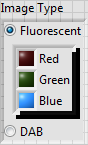
Create a custom control fantasy
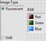
I am trying to create a Custom Control fancy image processing of the meter of cells. I want control which allows me to select the image of two types, fluorescent or DAB, and if I choose Fluorescent, will allow me to choose red, green or blue.
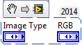
I created two radio button controls, one for Fluorescent / DAB, one for RGB, which looks like this:
I was hoping to "embed" the RGB control of the Type of Image control while having them retain their properties (box of dialogue elements 2 and 3 elements). When I made the simple drag and drop of RGB on the Type of Image, he acted as if I added elements of a cluster, and I got a box of the 5 elements, not what I wanted.
Then I'm smart and dragged Type of Image on top of RGB. Of course, if the Type of Image is at the front, you see RGB. However, if RGB is in front, see you both, but with ugly shadows around RGB (I made her invisible label).
Anyone have an idea how I can have my cake and eat it, too? Specifically, how can I get rid of the shadow that the RGB control throws on the Type of Image control?
Here are the controls themselves, as the excerpts:
Bob Schor
How about as a red box Fluorescent, Green Fluorescent, Fluorescent blue and DAB?
Lynn
-
Using custom control: draw a line and output start and end points
I'm looking to find or make a custom control (or simple Subvi), which appears as a grid of 100 x 100 unit and allow me to draw a line from one point to another on this grid. It will then display (x, y) of departure and the point of this line on the grid. Any help or ideas?
Thank you
Steve
LabVIEW 2009 SP1
You want essentially is a loop with an event structure when you process mouse down, move and up to events for the controls. There are several ways to implement something like that, but it will be probably the simplest:
- Use a table or a listbox multicolumn for your grid. Hide scrollbars and headers.
- You can use the ActiveCell property to-2, - 2 to select all cells. You can then use the cell size property to define the exact size of the cell.
- Then you put a picture on the top of the table control and color its transparent background so that the table shows through. Property node allows you to ensure that both line up on exactly the same location and size.
- You use the mouse on the image control events to detect clicks and moves.
- Point of the table to the method of the column line allows you to translate the position data of the event to a cell.
- You use the image control screws to draw the line on the photo based on these data.
- You can even color the cells selected in the table by using the table properties.
If you want to simplify things a bit, you can also use the event of timeout instead of moving the mouse event to draw the line, but then you keep the timeout value in a shift register and hand it to-1 (no timeout) when the mouse event to the top.
I would also say treatment mouse enter and leave events to change the cursor and cancellation if the user leaves in the middle of drag.
Maybe you are looking for
-
Programmatically formatting graphic mixed signals
I am writing an FPGA application where I am acquiring data from a unit under test (USE). The PXI-7842R digitizes 3 groups of signals: 1. an analog voltage monitor 2. 5 digital signals connected to the analog inputs (limitation of the pinout of the co
-
Why phot out much darker when printed that they are on a camera Any Solution?
-
Stop codes that are resolved by the response of error reports
Original title: Can I get help with a miserable Tablet? My Windows XP Tablet has some odd features and I think that some problem. For example, I used it just with Outlook 2003 and IE 8 open and when I clicked on the X in the corner of IE to close, my
-
I lost my cd, is it ok if I download an iso image and use my OWN windows xp pro key?
I really need help on this bad!
-
Please give me the link from where I can download windows xp directly.