DF bit value IP sla icmp
I want to put a mechanism to control the reachbility between two nodes by using the property intellectual ALS, but I find no definition df bit for ip sla icmp packets, y at - it ideas to do?
Best regards.
Hello
int f1/0
no ip policy map route df
output
local policy IP map route df
Kind regards.
Alain
Remember messages useful rate.
Tags: Cisco Network
Similar Questions
-
How Photoshop converts the RGB 16-bit values to 15-bit and 8-bit?
Can someone please help me understand what rounding of diet or another algorithm is used when Photoshop reduced a 16-bit color 8-bit?
For example, the two colors (was and B) are the colours of 16-bit swatch taken directly from a file of the ACO:
A16 = (61603, 60948, 58982)
B16 = (58326, 57015, 52428)
Photoshop displays the values of "16-bit" (acutally 15 bits) as well:
A15 = (30802, 30474, 29491)
B15 = (29163, 28508, 26214)
It seems that the 15-bit values are the result of the division by two and rounded to the nearest integer.
With 8-bit, it's another story although:
A8 = (240, 237, 229)
B8 = (222, 227, 204)
Now, if we divide the 16-bit value by 256, the following:
A8_float = (240.6, 238,1, 230,4)
B8_float = (227,8, 222,7, 204.8)
It's a similar story during the allocation of the 15 by 128 bit values. No system rounding or truncation will get the same answers as Photoshop for 8 bit I see. What I can't work, it's how Photoshop calculates these figures. It's the division of integers, floating point division with rounding or truncation? I'm puzzled. Help, please.
-> range 32768-65535: (32768 * x + 32767) / 65535
Not quite dividing by 2, otherwise you miss the white point.
32768-> 255 range: (255 * x + 16384) / 32768
With the exception of dithering, it is all simple mathematics.
-
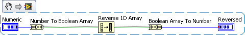
How to reverse the order of a 8-bit value
Hello
I want to produce a mirror of an 8-bit digital value. Suppose that my value is 11101100, my output should be 00110111. How can I get it?
Here's a solution.
-
Qosmio F50-12 b Win7 64 bit driver problems affects Fn, Power Saver, Tablet
Hello
I have Toshiba Qosmio F50 - 12 b. initially, I have Vista Ultimate 32 bit, then I refresh installation of Windows 7 Ultimate 64-bit...
This is the problem,I installed all the drivers for my operating system and the computer, but I can not installed or activated FN key, TouchPad, PowerSaver of Toshiba and the keys palpable above the keys of Func/digital as Dolbly, Media Center, Forward, Backward, Mute-, lights-touchpad on - off utility.
? also tried vista 64 drivers for these things, but nothing works to them.
I tried auto updater Toshiba win 7driver tool (tsi4win7.exe), but nothing changes.
I need help on this situation... Is anyone know how active these utilities, in particular the FN keys and touchpad!Thank you...
I hope that the Toshiba support my voice up and help this time :)
Hi mate
The 64-bit value Wi7 package and Support of Flash memory card utility must be installed.
Flash Card Support utility controls the FN keys and you should install it, after installation of VAP.Also the media control buttons should work after the installation of the package value.
-
How cascading 2 counters for 64-bit timer?
I work with the PCI-6225 card which has several counters. I configured CTR0 to 20 MHz. I get the CTR0 time by calling the OR-DAQmx C function 'DAQmxReadCounterScalarU32' to get the number of frequencies and then by dividing the number of frequency of 20 MHz for a time value. The maximum time value that may be getting is that of 214.7483648 seconds (2 ^ 32 / 20e6). I want to stunt/link two counters (CTR0 and CTR1) to get the frequency of 64-bit values. To be clear, CTR0 configured as CTR1 configured as 32 byte MSB and LSB 32 bits so that whenever CTR0 reached maximum values and "roll" then CTR1 would be incremented by 1. How can I do this using the C-NOR-DAQmx features?
Thank you
Ian
Hw do will be more reliable, but here are two possible ways to approach it in sw.
1. There is a DAQmx property with a name similar to "Terminal number reached" that I have used in LabVIEW but do not know the underlying C syntax. When you query this software, it will return a true once, is reset to false. I'm sure that he will return a true even once on the * following * the event rollover, but you would be better double-check me on that. Not knowing your entire application, I guess you will probably need to be prepared to manage several inversions.
2. in certain applications, rather than establishing a measure which follows the cumulative time, you can configure the hw to measure periods and then take a NAP in sw to get your 'timestamp '. Unless an individual interval could exceed 200 + seconds, you can just do your accumulation of software with a 64-bit data type.
Technically, you can even do both. Do a measure 32-bit intervals hw, do a query of software for the event of tc, accumulate intervals & counties of reversal in a 64-bit int.
-Kevin P
-
Hello world
After 10 years of LabVIEW experience I'm totally lost.

It's my first project with DAQmx and I do not know how to handle.

My configuration: Windows7. LabVIEW 2012 DevSuite; X Series USB-6366
My goal: trigger value encoder and 2 inputs analog
I would get a result for the value of the encoder and each of the two analog inputs for each change of the value of the encoder (not more! I do not want to sort a huge amount of data afterwards)
I was able to configure it with the measurement and Automation Explorer, but have no idea how to do that in a LabVIEW configuration.
Read all of the examples I could find the analog inputs and the encoder with SampleClock. This isn't what I'm looking for.
I would be very happy if someone could guide me to my solution.
I have attached the confiuration exported from the measurement and Automation Explorer.
Thanks in advance, best regards,.
Balze
P.S.: Sorry I got COMPRESS the *.nce file, because NEITHER allows you to attach files *.nce

You'll get there, but yes, the first exhibition to DAQmx is probably a little overwhelming. A few other tips based on your screenshot (I'm on LV2010 & can't open the code).
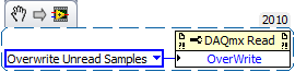
1. "allow buffer overwrites" is that a functional but description is not text. It lies under the Read DAQmx property node and must be configured before starting the task. Here is an excerpt:
2. it is usually (but not always) an available timing system to be used for all HAVE channels in a task just by the material. As a result, all channels to HAVE should be included in a single task. You can do this easily in chaining your call 'DAQmx create Virtual Channel' twice the job output and input/output error. Because the second call will receive a task refnum as input, it will configure the 2nd channel of AI to be part of the same task.
(It is possible to specify just several channels in a single call, but separate calls gives you the ability to configure different setting on the scale or range of entry).
3. the 'random', which IA task gave you the error is due to the lack of sequencing in your attempts to start tasks. The question which is the fortunate success that happens to run first can (and does) vary from run to run. By combining the two channels to HAVE in a single task, this problem will disappear, but you want to be sure that the tasks of the AI and the counter are started * before * any clock signals come to PFI8.
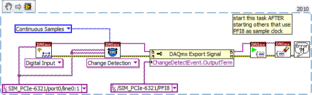
4. "change detection" will be available for digital input assignments, not tasks of meter. And it is also generally supported only for a digital port a-bit value. Other ports then that support data acq clocked by the software on demand. I guess one of these questions is the source of your error.
On the boards of the M series that I used, change detection has been supported only on port 0 - I think that the same thing will be true for the X-series cards. The following took place without error for me using a simulated X series device. By selecting another port gave an error.
-
FIR SC645 Cam Options and 16 bit Image to the conversion of temperature
Hello
I plugged a FLIR SC645 camera via an ethernet connection to my pc.
In Max OR one can see the camera unther NI IMAQdx peripheral. Here I can take a picture and change the focus through the attributes of the camera.
I did a small test program with the "IMAQdx - Snap.vi" so now I have a 16-bit grayscale image.
This estmaintenant Image saturated it start in black like the temperature in the room and turns white at high temp +-90 ° C.
When I measure a halogen lamp, which is about 115 ° C wil gray color goes out again to go above 90 ° C.
How can I change the measuring range.
How can I change the focal length?
How to convert the gray Image 16-bit values to temperature according to the measuring range?
I hope sombody can help me with this,
The type of the input image is not serious IMAQdx because it will convert its format of results. The signedness pixel attribute should work. I suggest to play with MAX attributes first. You can then save the settings and use them in your application.
-
simply recover 16-bit int instead of double?
Hello
I have a usb-6210, which has a resolution of 16 bits. to my surprise, I double values (64-bit) when I use studio measurement in c#. It is a waste of memory, but I couldn't get the driver to provide 16-bit values (integer or binary or other values). I don't want to lose the ability of calculation with conversions after extraction.
How can I get the 16-bit values of the device?
Thanks in advance!
that s it, thank you!
-
Appeal of kernel32.dll crashes LV2011 SP1 64-bit
Hi all
I'm moving an applciation of LV2011 SP1 on Windows XP SP1 LV2011 64 bit on Win7 64 bit.
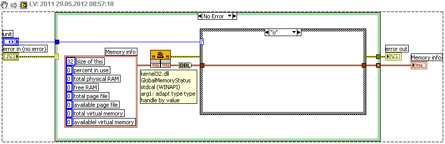
In my application I am making calls to the file kernel32.dll to know how much of RAM is available on the computer, this is the VI I use for this:
To call the dll, I only give the name of the "kernel32.dll" and not the full path.
I never had problems with it on Win XP and now that I'm on Win7 64 bit, when I run this VI, LV disappears just far with no message of accident and when I restart, it won't crash recovery process.
I went in the C:\Windows\System folder and seen that there are two files kernel32.dll, one in the System32 subfolder and the other in the SysWOW64 subfolder.
I tried to give the full path of the two versions of the dll in the node of the call, but I keep getting the same result.
No idea what should I do to make this work?
I guess I could give up by using a call to the dll and use some .NET features but I'm really not familiar with it.
I think your problem is that 64-bit systems, SIZE_T (the data type for most of the parameters of the structure) is 64-bit, and you have not signed it, 32-bit values.
-
How to convert power into binary data values
Hey.
I need to build a VI that I input to a power (from 0 to 300 W) value and then convert that value to a 12-bit binary value, should be sent to DAC from my electronics and control power.
I was reading things about numbers fixed-point, but has not come to firm conclusions.
Since I have 4095 numbers in a 12-bit value, I can have a precision of 0,07326 in my controls.
To sum up, when I run my minimum value (0 W) I want a bytes 0000-0000-0000;
When I throw my maximum value (300 W) I want a byte 1111-1111-1111.
Guys please help me about what are the tools I use to build this?
Thank you!
pedroseger wrote:
I'm pretty new to labview, so I'm sorry for the basic response, but this scale you are talking about: How do we? Properties-> data entry?
You don't say what kind of data is that the instrument. Here are some possibilities showing the scaling.
-
Is MODBUS RTU - always necessary to convert 2 * 16-bit to 32-bit?
I have spent a lot of time on forums try to solve this problem, and as of yet I have been unable to
Fix it.
I am reading a sensor of Carlo Gavazzi DC Modbus (programming manual attached) and were
getting a mixture of correct and incorrect values when reading from the device.
I use the library Modbus Labview who reads 16 bits of the default individual registries and what has
in general, been very well unless all negative values are involved. My access to each register method is simply
a loop by using the Example2_VI and iteration records required.
I am mainly interested in the following
Address:
 arameter::Register Value::Expected value
0::voltage:476: 47.6V (that's okay)
1::voltage:0:
4::current:65446:A couple of (negative) amps up! No 89 / 6500 a
5::current:65535:
Negative values do occur when the system (generator) is not running. When it actually works
the current 16-bit values can vary from 40 a to 250 a, but they are all incorrect by a factor of at least 10 to 20%.
I tried to use the example of vi to combine the current values in some way to return anything meaningful, but
whenever she repeats just NaN (not a number, I guess) so I'm wondering if I should make some sort of calculation
before I feed them in the type cast?
Try this.

-
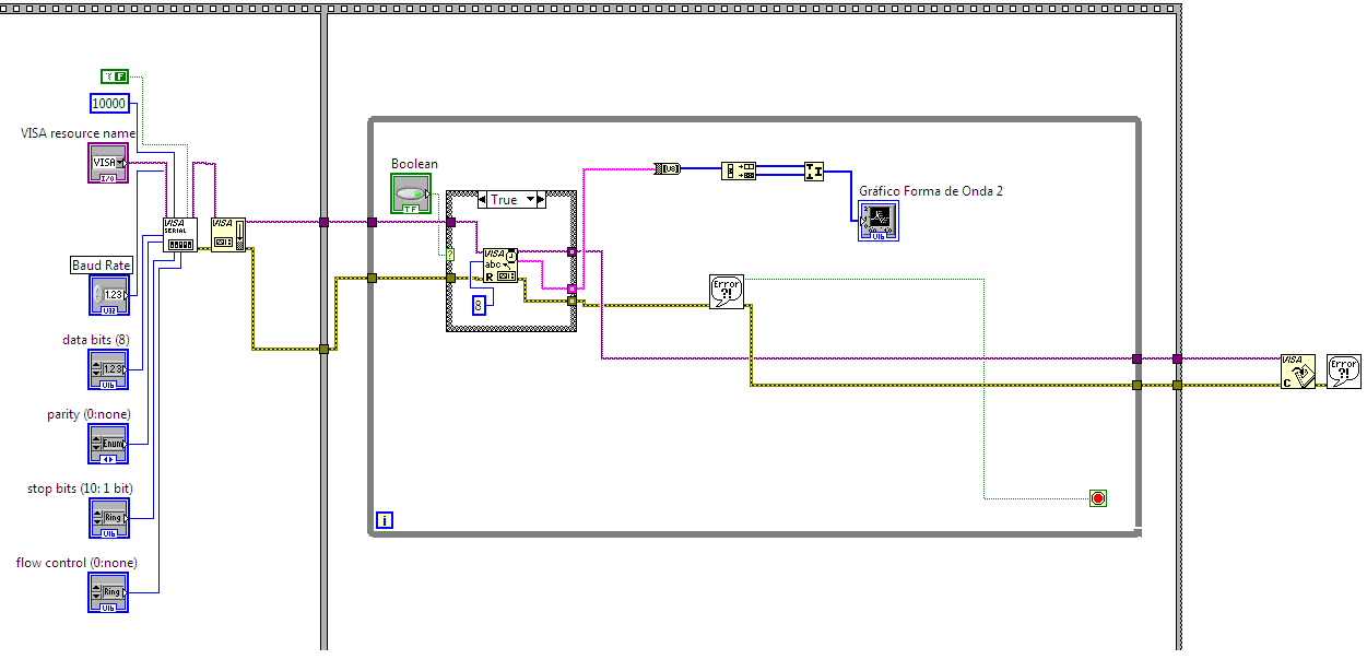
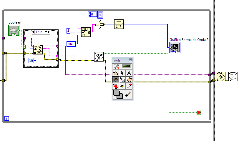
2 ways to send 16-bit to the serial port. What is the good?
I am trying to send data via a serial port... This data consists of a 16-bit format. The data are sent by a DSP. Searching in the internet I found two ways to send data. The first is that the first photo anda the second way is the second picture. I read data ok, which in this case is a sine wave. But I 'don't know if it is correct or not.
In the first case , the citation read buffer sende th 8-bit to decimate them VI that will be concatenated after to join numbers function...
Is it fair or not? Second question. I noticed when I put multiples of 8 in the number of bytes the graph is ok. But when the number is not a multiple is the graph 'missing pieces '. Why?
In the second case, I confess I didn't undertood it. I know that the CASTING of TYPE function transforms the string on a table swap bytes (DSP sends the MSB and LSB) I know what subset of string. I read that the 4 in the offset is put there to avoid the reading of the data header. But I don't know why 2048 is here. The latter reads data too...
With any who answer my questions would be a really really help
Thank you guys.
First case
second case
Both are probably correct for the data being sent.
If you want to read a unique 16-bit value at a time, then obviously you would set the number of bytes to read to be 2. The following code shows two ways to convert the two bytes to a single value. The chain Unflatten to specify the boutien.

You don't mention her, but how do you synchronize the data. With the dsp to send two separate bytes, not sure what byte you will read first. Do you send start/stop characters so that you know this vital information?
-
How to convert the value of byte in two asci characters
I have a problem that is perhaps easy to solve, but I do not know the answer.
Is it possible to convert a value of binary characters byte two asci.
For example:
There is a 8-bit value, 0.
I want to have two characters distinct ASCI (string). 0 and has.
Thanks for any help.
I have the solution. Sorry to ask this question.
Convert this byte with 'Number of hexadecimal string', separate this string in two characters and ready is.
-
Understand the values fixed point of a NOR-9203
I have a cRIO-9073 with a NI 9203 module. In LabVIEW FPGA, the card values are returned as a fixed point. LabVIEW chosen fixed point properties are (+/-, 21-4) that apparently offers a range of (- 3.125E - 2, 3.125E - 2, 2.98E - 8), and the current card in the range 4-20 MA with a resolution of only 16 - bit. My understanding of fixed point values is only slightly, then someone can explain to me why a 21-bit value is required for the 16 - bit acquisition data?
Hi Thoric,
Sorry, it took a while to get a response to you. The necessary extra bits with fixed point representation are for the overflow feature. There is more information in the link below.
http://zone.NI.com/reference/en-XX/help/371361E-01/lvconcepts/numeric_data/#FXP_overflow
I hope that this answer to your question, but if you need more help please let me know.
Kind regards
Thomas Clark
-
7510 trials network connects to 64-bit WEP. Must be 128. How to change the printer?
New 7510 C311a wireless printer. Does not connect to the existing airport extreme - does not recognize the password. Printer security WEP key has the 64-bit value. Network uses 128bits. Is there a way to change the settings of the printer to 128?
This may be a better solution - do not use WEP - it is not in the least safe, your WEP key can be guessed in about 10 minutes with the freeware on the Internet.
Choose encryption WPA/WPA2 Personal on your airport, create your own password for 12 + character and be much more secure and have a system easier to use.
Maybe you are looking for
-
I work on windows XP I have latest fire fox and silver light plugin 'Silver plugin light crashed', that's what I get when I try to attach files in hotmail error report on plugin - container.exe. where to find the plugin - container.exe. to install an
-
Map of low-profile Office of H8 - 1534 with bluetooth wireless network
Who will the brands/models of PCIe wireless with bluetooth cards work with my computer running Windows 8?
-
Hello world Can someone help me please. Im tring to locate and download the software for my M426fdw Laserjet printer called HP SCAN that controls your printer to scan, fax, etc. Could someone providie a link? I reinstalled the full package, but it do
-
RAZR: Recommend recharging with a charger included.
Finally received my miro sim card this morning. Called my service provider (O2) to activate it and was saying to insert SIM switch off the handset for half an hour and then when I turned it on again it would be activated. I waited for half an hour an
-
Installation of Service Pack 1 completely destroyed my PC (VISTA)
I tried to install service pack 1 sent automatically and the PC was never able to recover. I tried all the available recovery tools, but Windows may not start in any mode. What am I supposed to do? The PC is completely dead. Thank youAlex HP DV2745se