Example: "-Conitinuous digital output" how it works?
I generate a sequence on three channels (with my NI 9375 output digital map on a cDAQ9188).
In 1 second, the sequence consists of, for example:
channel 1: start low... on 15 high ms... on 865 ms low again
Channel 2: from high... of 115 low ms... on 650 ms high again
Channel 3: start low... of the 85 high ms... on 920 ms low again
It must be generated and material conituously timed.
For this application, they advised me to work with the example of 'Digital - continuous output. Can someone explain to me how to get this sequence with the control box "Write data" on the front panel? And how can I visualize my generated sequence?
Thanks in advance!
Tags: NI Software
Similar Questions
-
PCIe-7842R (series R FPGA) digital output does not work properly
Greetings,
I'm having some problem show TTL the correct voltage with my PCIe-7842R FPGA board.
The block diagram of my code FPGA LV Moose appears in "analog - digital .png '. The idea was to convert an analog input (decimal value) to a binary code and 16-bit output by 16 DIO ports. I use the connection block SCB-68 has as the terminal and trendy on the FPGA 1 connector RDIO with SHC68-68-RDIO shielded cable.
The compiled code ok. But during the test, I noticed that some ports has no output TTL levels correctly. For example, for input 1000 decimal, I would expect binary code 0000001111101000. However, some ports (DIO #6, #7, #9, etc.), which are supposed to ~3.3V (1 digital) high TTL output, output actually 0.8V. I have attached the result measured in 'exit digital test.png '.
To ensure that the question was not because of the code of the LV, I did some more tests on DIO #6 with a simple example (simple digital output.png). The output was ~ 1V this time at the digital 1.
It's really confusing because of the digital Edition is supposed to be simple. I used the same FPGA card for controlling roller shutters with TTL signals before and it worked fine.
Does anyone have similar problems? Any suggestions are greatly appreciated.
iron_curtain wrote:
DIOs are connected to a controller digital galvo Cambridge Tech. But I measured the voltage at the terminals of the connector block.
If you unplug the controller galvo DIOs, do they look good (have the right voltages). Do you know how many of these entries to the need for controller? I think you hit the limit the total current available for EID within the Council.
-
How to secure the wiring of digital output BNC-2090
Hi, I'm working on using the digital output of data acquisition to control the digital DAC input, but I have a problem on how to fix the wiring for the digital output of the DAC. When I plug the cable into the hole, it is vaguely related. Any suggestions on how to fix the wiring are appreciated.
Thanks in advance!
It is a spring terminal.
Try to push in the orange tab with a screwdriver while pushing in the thread. Release tab to release the wire, and it must grab and hold the wire. It may be a case involving Orange instead of push. You should be able to understand.
-
How to synchronize 2 digital output channels that have been created with DAQmxCreateCOPulseChanFreq
Hello
I use peripheral USB6221.
I created two digital output, operating on a frequency of 75KHz and duty cycle of 50%. But I need a period of 1 microsecond between the two channels.
I have craeted the two channel on the same task and guess if I use a delay of 0, the channels will be synchronized, but looking at the scope, the channels are not synchronized. Here's the code I used (I checked also all return codes of coarse and fine).
Thank you
Danny.
Int32 RetCode;
RetCode = DAQmxCreateTask ("", & m_OCtaskHandle);
LogMessage (RetCode, "CreateTask", "");
If (RetCode > = 0)
{
define the first output channel for 1 transmitter (75KHz)
RetCode = DAQmxCreateCOPulseChanFreq (m_OCtaskHandle, "/ Dev1/ctr0", ")
"Transmit1 Line 1", / * name to assign to the channel * /.
DAQmx_Val_Hz, DAQmx_Val_High,
0.0, / * initial delay in seconds * /.
75000.0, / * Freq * /.
0.5 / * market factor * /);
define the second output channel for 1 transmitter (75KHz with 1 microsecond delay)
RetCode = DAQmxCreateCOPulseChanFreq (m_OCtaskHandle, "/ Dev1/ctr1", ")
"Line2 Transmitt1", / * name to assign to the channel * /.
DAQmx_Val_Hz, DAQmx_Val_High,
0,000001, / * initial delay * /.
75000.0, / * Freq * /.
0.5 / * market factor * /);
Describe all channels continuous task
RetCode = DAQmxCfgImplicitTiming (m_OCtaskHandle, DAQmx_Val_ContSamps, 1000 / * I think that NA since continuous * /);RetCode = DAQmxStartTask (m_OCtaskHandle);
Hello Danny,
If you are looking for more output channels of the Digital pulse trains, you can create 1 task of counter that is used as the clock for digital multi-line data output. For this digital task, you will need to make the clock source line PFI for the output of your task of counter. Once this has been done, you will need to create the digital signal for each line of output and write to the card. The example called write dig Chan - Ext Clk will explain how to set up the digital task so that the task has an external clock (the counter). I hope this information helps you and if you have any other questions, feel free to post.
-
How can I create delays for many digital outputs?
I use a PXI 6537 DAQ card to produce four digital signals for each starting at a different time. In order to create this delay the appropriate number of '0' have been placed at the front of the boolean table before converting it into a digital signal. It works by creating the delay, however using this process, the delay may be discrete increments equal to 1/╔chantillonnage and my card can be up to 50 MHz, this means that I can produce only delays 20ns increments (check my calculations). For my application, I need to be able to control the time until the second nano. Delays will usually be more than 20 ns, but less than 40ns. I tried to use the entry 'to' the 'build waveform.vi' but it doesn't seem to do anything to manipulate the data. The sub VI used to create the waveform is attached. Sending the data isn't a problem. Thanks in adavnce for any suggestion.
JS
Hi JS.
The 6537 allow placement of subsample edge on its i/o lines. The best you can do is unique (like you the noticed) examples of resolution (20 ns @ 50 MHz).
Have you looked at the SMU-6545? It is a 200 MHz Board, which means that you will get 5 placement ns, as WELL as data delay feature which lets you place your samples with ~ 150ps resolution compared to the output clock.
Are you having to change the location of a signal in the clock period each cycle? Or is the position fixed by reference to the clock, but must be placed exactly?
Thank you
Keith Shapiro
National Instruments R & D
-
How to configure the digital output of the pci terjeta 6023E in LabVIEW 8.5?
Hi, I have a card PCI-6023E and LabVIEW 8.5 and I need is to configure the digital output on the card, but did not.
My idea is to get a port of digital data on the map and control by a pwm small dc motor.
I wonder what are the modules with which you can do.Hi skudero,
Probably the web page tracking and the attached example will work.
PWM in software timing using a digital output line
Concerning
Charley - NIB - SR 1368189
-
How to generate the digital output of the variable duty cycle and clock source being contrary?
I want to generate a digital pulse every front amount of my pulse counters. He must have a variable duty cycle. until now, I've been able to generate a digital output, but I can't change its duty cycle.
pls tell how I should proceed?
Thank you in advance...
-
How to quit smoking all the void s vi before resetting digital outputs and then closing
I have a project that contains a main VI called home screen that calls many different sub vi. I am monitoring for a press of physical button by a digital input with a DAQ Assistant on the main VI and in this case I want my program to abandon all of its VI running and reset all the digital outputs before the closure of Labview. No idea how I would go all this?
I have attatched the basic model of what I do.
Joelspider33 wrote:
The problem is more to do with some of my money that VI running a DAQ Assistant using the same digital lines like the ones I'm wanting to reset and causing it to throw up an error message.
This is why you must set the DIO AFTER all subVIs are arrested. And to do this, you must send messages to these subVIs telling them to stop. If done correctly, it is a very quick process.
-
How can I more easily generate a pulse of digital output of finite length?
Hello
I need to open and close the two pneumatic valves using a TTL output (without load current or the output power) using a PCI-6280 or PCI-6601. The valves must open almost simultaneously and closing after different amounts of time elapsed (millisecond level timing, maybe 100 microseconds-level timing at worst). My current plan is as follows:
-Create a task with two digital outputs (type of waveform) and another task with a counter that generates a frequency set by the user (I know I can use the generator frequencies on one of these cards, but I would have preferred a counter - the best selection of frequencies).
-Wire the output of the counter at the entrance to clock two digital outputs.
-Output of the meter is digitally triggered by another digital channel which I use to control if the pulse goes out. Through its counter node, it is programmed to be redeclenchables.
-Two digital waveforms are drafted who have both consist of unique active high pulse (i.e. signals go ' down (for the amount of time user-defined) - low ".")
-These signals is written to their respective ports and their tasks have started, as is the task of the meter.
-Whenever the user wants to open taps, digital triggering is sent up and then back to low (this can be done with synchronization software, because it is not exactly when the fire valves). Whenever the user wants the valves open for a different period, different digital waveforms are generated and written in the buffers of the digital output channels.
My problem is that it looks like a lot of effort for me to go and I wonder if there is a much simpler solution, that I don't know everything. You can program a computer to produce a pulse of finite length? Is there a faster way to program a digital output for that channel?
Thanks to anyone who responds to their help.
It is certainly instructive. Thank you.
The thing is, I have only six total counters to work with and I have a lot of time to do things. To use these solutions, I would need to use 4 or 6 account counters required to my needs.also that I would need to synchronize their departures.
Overall, I stick to my method for now - less system resources and synchronization can be don by using the same meter of finished output clock and not to use a trigger to all.
Once again, thank you for your help so far.
-
How can I write a digital waveform to the digital output (traditional DAQ)
Hello
I use a NI 6023e, PCI, with 8 digital outputs. I generated a digital waveform. How can I write for a specific digital production line now?
I only have Labview 7, so I can't use DAQmx.
Thank you very much
-
Original title: unplugged... HDMI?
So I have a laptop Vaio of microsoft. The microphone that was integrated into the laptop was working fine until recently. No, I talked through my laptop was able to hear me except through Skype. I search through my laptop and say something like in the playback than digital output device or interface (HDMI) was disconnected. I know very well that I unplugged it. Can someone please?
Hello
1 did you change on your computer before this problem?
2. you receive an error message?
3. What is the exact make and model of your laptop?
4. are you able to record from Microphone?
5. which version of the operating system is installed on your computer?
What version of the operating system Windows am I running?
http://Windows.Microsoft.com/en-us/Windows7/help/which-version-of-the-Windows-operating-system-am-i-running
Make sure that the Microphone settings are set up correctly.
a. right click on the Volume icon in the notification area.
b. go to recorders and right click on the empty area.
c. Select Show disconnected devices and show disabled devices.
d. right click Microphone, and select activate.
e. Microphone right click and select Properties.
f. Select the option use this device for the use of the device falling down.
g. go to the levels tab and move the slider to the maximum level.
h. click on apply and OK.
See also:
Tips for solving common audio problems
http://Windows.Microsoft.com/en-in/Windows7/tips-for-fixing-common-sound-problems -
How to measure the digital output of the linear actuator on USB-6009?
Hello
I am a new user of Labview and need help to measure a digital input signal.
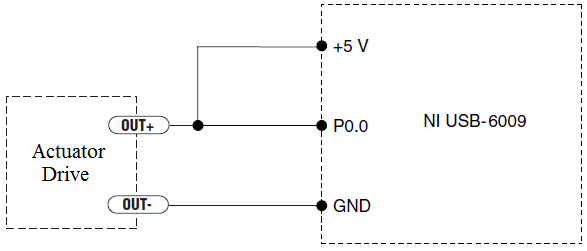
I have an actuator Bimba Original line electric with a motor continuous integrated with encoder, drive and the controller. The drive has a programmable digital output that I put as a tachometer output that emits pulses of square wave 100 per turn of the engine. I put the engine to make a total of 56 rev in 22 dry. I want to measure the speed of motor rotation labview real-time and synchronize it with a few other analog input signals. I wired the actuator for the USB-6009 case as shown below.
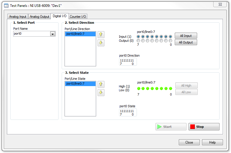
I opened the test i/o digital USB-6009 Panel and fix all the lines of port 0 as inputs. However, when I click on start and run the actuator, p0.0 led flashes, as indicated below.
Shouldn't the led blink in response to revolutions of engines?
I want basically to collect the drive pulse signals and convert them in rpm on labview.
ahsan2 wrote:
I have it wired correctly?
It would help if you do not attach the HIGH signal. Remove the + 5V in the circuit.
-
How can I improve my 2 digital output signals calendar?
Hello
I use a NI DAQ Pad-6015 (usb) with Labview 8.5 and XP to generate 2 digital outputs (high for the first 500ms and 600ms high for the second). The moment didn't need to be very specific, so I use not the 2 outputs hardware clocks. When runing of VI, and measure the length of the outputs with an oscilloscope, I get s 520ms and 640ms. This isn't a problem, but I still want to know, if I'm doing the right thing in my program, or if it is possible to improve it?
Thanks for your help,
Kind regards
Marc
Hello
Using all your advice I have exact measure now: only 0 to 4ms delay for signals from ms 500 and 600 using the NI DAQPad-6015.
PS: Timmer was right regarding the notice of usb. With my previous program when you use a card PCI of 6229, I had only a difference of 10 ms instead of 20 ms with the usb one.
Thanks for your help,
Kind regards
Marc
-
take the digital output USB-6001 always high or low in c
Hi all
I am new to the NI DAQ interface. I have a USB-6001 and I am trying to use this device to control some flowchart in C. What I want to do is:
* set digital output lines with high and low intensity and change their status as needed (in C).
I tested the device NEITHER Max--> Test panels and found that the device is capable to do that. Then I try to do in C. I have checked hace examples and function I use is one called "DAQmxWriteDigitalU32". I have problem in the understanding of its input parameters. I tried something with my own knowledge, but it does not work as I expected. Here is a test I did:
data uInt32 = 1;
Int32 wrote;
TaskHandle taskHandle = 0;
DAQmxErrChk (DAQmxCreateTask("",&taskHandle));
DAQmxErrChk (DAQmxCreateDOChan (taskHandle, "Dev1/port0/line7", "", DAQmx_Val_ChanForAllLines));
DAQmxErrChk (DAQmxStartTask (taskHandle));
DAQmxErrChk (DAQmxWriteDigitalU32(taskHandle,1,1,10.0,DAQmx_Val_GroupByChannel,&data,&written,));taskHandle = 0;
DAQmxErrChk (DAQmxCreateTask("",&taskHandle));
DAQmxErrChk (DAQmxCreateDOChan (taskHandle, "Dev1/port0/$line0", "", DAQmx_Val_ChanForAllLines));
DAQmxErrChk (DAQmxStartTask (taskHandle));
DAQmxErrChk (DAQmxWriteDigitalU32(taskHandle,1,1,10.0,DAQmx_Val_GroupByChannel,&data,&written,));I just want to set ' Dev1/port0/line7' and ' Dev1/port0/$line0"at a high level, but only ' Dev1/port0/$line0' answer me. The second parameter of the DAQmxWriteDigitalU32 function is numSampsPerChan. If I replace (currently 1) with a higher value, such as 100, I see that "Dev1/port0/line7" sends a number of 1 output, then back to 0. So I guess that the problem is just that I understand not all parameters for the DAQmxWriteDigitalU32 function. Is someone can you please tell me how I can set up a line of digital output 1 or 0?
Thank you!
Hongkun
Hello
I finally find a way to do it! The feature works very well, and my problem was not set the data value to write correctly. It seems that if I want to write a 1 to the port0/line1, I put "data = 2 ^ 1" rather than "data = 1", because by default it is the second bit of the port.» Similarly, "data = 2 ^ 7 ' high level to port0/line7. I find that this setting is surprising when you want to control an individual line. It seems more reasonable when you control the whole port. In any case, is to solve the problem!
Thanks anyway!
Hongkun
-
analog sync of input with the onset of the digital output
I'm trying out an analog signal to a file with a specified frequency samples. I also need a digital output to trigger a measurement at a frequency specified on a separate system. The frequency is controlled by the loop exits and timed when the iteration number divided by the period is exactly a whole number.
Both outputs work. The problem is that they are not synchronized. The analog output amounts to about 0.5 ms faster than the digital signal. (I checked with an oscilloscope) They both start in the 1 ms each loop runs for, but I really need them to start at the same instant. What can I do to synchronize? Also, if I'm going in the wrong direction complete, please indicate.
I use a card PCI-6723, which I think someone at some point, said not having a material sample clock. That's why I try to use a timed software loop.
Hi NEA.
You must use the 6723's built-in calendar to accomplish what you want. As the digital output subsystem is only clocked by the software, an appropriate solution should be to use one of the counters to the pulse output.
The attached code should show how. You can use the counter to output a pulse all samples of the AO N task. Material requires the initial delay to have a minimum of 2 ticks, so the meter will be behind the task of the AO by 2 samples in this case. There are different ways to work around this problem if you need (for example write two samples of 0 first).
Best regards
Maybe you are looking for
-
Satellite L500-19 - remove the recovery partition and create new
Hello! I bought a new Toshiba Satellite L500-19th with Windows 7 Home Premium (64-bit). So far, everything is brilliant work.I have already created the recovery DVDs.As a result, could now delete the partition with the recovery program? I want to use
-
acquisition of signals from multiple cards simultaneously
Hello I am trying to acquire the signal of my cards OR PXI simultaneously but having some difficulties to implement which. Here is my configuration: Installation of equipment: (1) chassis NI SMU-1071 (2) map of NI PXI - 4461-2 I / P and O/P 2 (3) map
-
The VI attached below runs whenever a user pushes a button on the front panel. It should run for 5 seconds before stopping. It's only a subvi, then it will not work if someone here open to it, but I hope that the solution to my problem will be easy t
-
How to uninstall windows powershell in vista
I'm trying to fix my computer and the cd said I need to uninstall windows powershell. I don't know what it is. Can you help me to unintall Vista Home premium?
-
Hello I have a problem with the reinstall an application on a BlackBerry device.After I reinstalled I asks me to reboot the device, but if I choose no I can always start the application. The problem is that the old application starts and I don't want