How to scrub the waveform?
When I zoomed in on the wave form is there a way to scroll which does not involve going up on the thumbnail and dragging the viewarea?
Yes. Since you don't want to use the zoom/scrub on the top bar, I guess you don't want too click you the tool hand on top of the screen either. Then press H to activate the hand tool, then you can rub it directly on the waveform. Press T to get the time selection tool regular return (or V for the move tool). You can also roll the mouse back and forth to zoom wheel, so you do not have the top bar for that, either. The center point of the zoom will be at the present time, you have selected.
For some reason, Soundbooth does not activate the hand the way tool that make other Adobe applications. In Photoshop or Illustrator, for example, you can press and hold H temporarily get tool, then let go and it snaps back to the previous tool. But in Soundbooth, press and hold the H are the same hit - you go to the tool, activating not temporarily.
Tags: Soundbooth
Similar Questions
-
How to rebuild the waveform with zero new and create histogram type of waveform?
Hello everyone, I have an application where I need to rebuild a waveform using some amount of 'x' of the data samples. the conditions are:
1. the new zero of the new waveform is peak value frm the old form of wave., allows to assign this value of y s.
2. based on this peak value, I have to draw points of sampling (y - t) and (y + t)...
the waveform above may look like a histogram, but isn't exactly a histogram... can anyone suggest a concept?
I'm not able to take the time to "throw in a sample VI.
But if you look at the help file get the subset of waveform, you will see that he has all the inputs you need.
There is an enum constant that allows you to choose samples or time. I would say that the samples since this is what will come from most of the table Max/Min detector or Peak live
There is a sample start time. Put in the value of your Ridge detector less t.
There was a time. Put in the value of t 2 times.
If t is the time, you may need to convert to samples based on your sample rate.
-
How to set the waveform table to start data since the beginning of the race
Create a property of the graph node. The property you are looking for is history. This property, you can clear the table.
-
How to make the waveform table rows less laeti WITHOUT using a lot of mathematics of interpolation
So I use a graph shaped wave, the numbers of entries sequence like that, sensor 22,23,24,25... the graph seems laeti. (Fussy) client says hey I want a good graph, you have function spline or something?
So I was to research the properties of chart and saw the settings below that does not help much. I proposed to the customer (picky) that Hey maybe we can make the balance Y greater for the lines of the stairs will be not so obvious, the customer (picky) says no. So I was sweating on tedious mathematics required for interpolation in the hot oil and noisy, without internet, fortunately the dinner bell rang.

Now is there some function blocks which makes the table lines smooter, a function spline or something? Thank you.
-
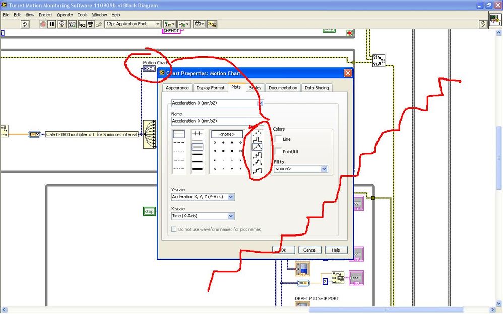
How to extract the signal from the waveform of my power level designated?
Hi all
How can I extract the signal of the waveform accroding to the power level? I read the Trigger & Gate .vi, but this vi retrieves the signal duration. I want to extract the signal depending on the power level.
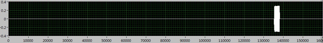
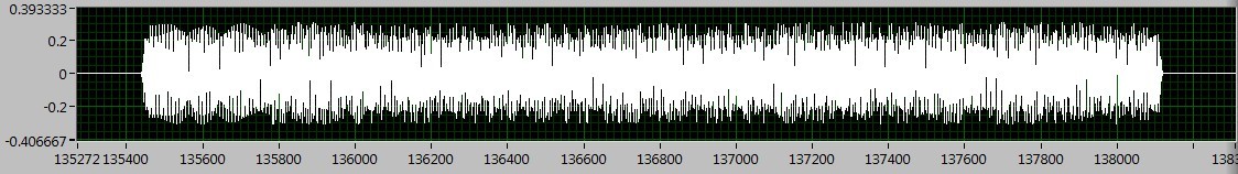
As shown in the following figures, the signal I want to deal with is between 130000 to 140000, if I Zoom, I can see the useful signal is between 135400 to 138200. The question is how to extract the signal in the area?
I tried the sub_NoiseEst_And_Chop_Shell.vi in the example of Packet_based_link also, but this Subvi seems to be a bit slow. Can someone give me the best advice? Thanks in advance!
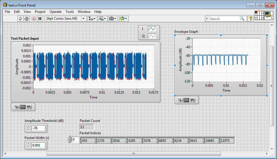
I'm working on something similar, but have not had time to fully develop.
My idea was to use an envelope detector (low pass filter) and then use a detection of energy VI on the envelope.
Here is where I left
-
To build the waveform.vi function how to calculate the value of dt
Dear all
Please guide me How to calculate the value of dt according to waveform.vi of construction
My sampling rate is 25000 and I take 200000 samples.
Kind regards
Muhammad Irfan
It's all simple arithmetic. The inverse of the sampling frequency power of samples is then the dt or the time between samples the number of samples is not relevant.
-
How to synchronize the start time in the waveform graph
Hi all
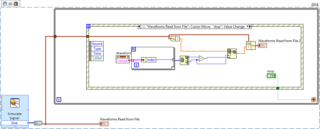
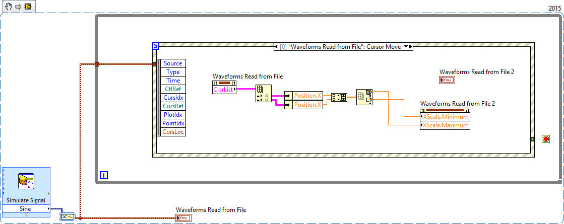
I just find a solution in the forum to select the data you want in a grap of waveform with cursors, however, I don't know how to synchronize the time of beginning of waveform for the second graph. How can I extract start time of the waveform with the index data?
Something like that? It is a bit gross, but is what I think you're asking, should be able to use it as a starting point.
The Max - Min is to make sure that the cursor is always valid.
-
How to table of waveform of input 1 d in the lock with the amplifier
I have a LabView application that I have to change to include a lock in the amplifier. The application uses a capture card of data several times to capture a sample of 0.1 s of two signals (one signal, a single reference) in a laboratory test. Before the measure was made by the base RMS module to record the VRM in the signal, and the reference is ignored. However, the measures that I am now the scene run many s a lower and so I would use a simple RECS in the kit OR of.
I am happy (I think) with the configuration of GARLIC but I am struggling to understand the requirement of input data. It should be an array of 2D, with the identifited of reference signal. However, the output of the part of the utility that captures the waveform is a table 1 d of waveform. Could someone advise me on how to convert the table 1 d of waveform in a 2D table suitable for admission to the GARLIC?
As you may have guessed that I am a newbie to LabView, I try to modify an application designed and assembled by a former colleague, so I'd appreciate simple suggestions!

TIA.
You have separated for each signal waveform 1 d arrays, or do you have a 1-d single waveform chart where signals are separate items in the table? If this is the first, you should do something like the code below. If you have a single Bay, then the code would be similar - you could just use a table of unique Index function. You may or may not need to transpose the table 2D. I don't know what waits for the lock in Subvi - channel data by row or column.

-
How to create the type of waveform data
Hello
I work with the oscilloscope TDS 30xx series and I want to create the data type of waveform in the waveform of Fetch VI.
I have problems with that. Can someone help me?
I don't know how to data table of waveform to the creation of a data type.
Is attached a photo of the VI and the VI himself
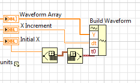
Well, if you want to build a waveform of Y, dT and T0, you can still use the function named "build the waveform.
-
How to calculate the polynomial graphic adjustment of waveform
Hi all
I am new to lab - view so would need a little assistance in one of the problem I have right now.
My problem is: how to calculate the polynomial graph of waveform data adjustment? I need to convert the waveform to XY graph data, and then use the polynomial vi made integrated to calculate the fitting?
Detail: My problem is that I have waveform graph, I calculate the vertices and the Valley, but because of the noise, my peaks and Valley detection is sometimes not exact, so to smooth the chart that I must apply the polynomial fit.
If anyone can help me in this, I'll be very grateful.
Thanks in advance
Hi Omar,.
have you seen the suggestion of Lynn above?
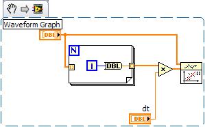
You already have the values of Y (your table). Now, you need build the table of X as indicated, only to replace the value of dt with your spacing from point to point. Somewhere in your code, you know that the value that you have an x-axis indicated in milliseconds...
-
FFT waveform (file converted from Matt file lvm) - how to overcome the error dt < = 0?
Hello
I use a lvm file after conversion of Matt file. I wanted to get the fft spectrum. I get this error message this dt waveform<>
How he overcome?
I have attached the matte file and the vi that I used.
Best regards
FESMI
The Forum is a bit special files that can be attached. Creating a zip file often works. Sometimes, you can change the .txt extension. If you change the extension, please indicate in your message which was the extension of the moose.
It seems that data in the file has a time column and a column of amplitude. The LabVIEW waveform data type is a cluster of a table of amplitudes (Y), sampling interval (dt), from the time (t0) and optional attributes. That's what the power spectrum VI requires as input. The t0 values is not used if the default is fine. the value of dt can be calculated by the difference of the two adjacent values in the time column. Given that the first value is equal to zero, the second value is equal to dt. Use the primitive to build a waveform of the palette of waveform. Expand it to view the dt element.
In the VI attached all lines is an indicator that contains your saved default file data. Graph XY plots that data. After subtracting the way to get rid of a continuous component, the data is converted to a waveform. The power spectrum is calculated and displayed using the same VI as in your program. It also uses extract several Information.vi tone for the frequency and amplitude of the main peaks in the data.
Interestingly, the lower frequency of the spectrum a harmonic of 60 Hz while the tops are almost sharp space 4 kHz ~ 100 Hz apart. The broad peak near 2.1 kHz does not seem to have noticeable components to 60 or 100 Hz.
How to avoid the Type of dynamic data (DDT)? Stop using screw Express! For reasons known only to EITHER screw Express a deliver their outputs via the DDT. Except when you open the block diagram of the express VI, there is no way of knowing what the underlying data structure on a thread of DDT.
Lynn
-
How can I display only a part of the scale in the waveform graph
This is the first time I try to use the waveform graph, since now, I used the table of waveform.
The reason why I moved to the chart, it's that I need cursors.I have 2 problem
the first: in the diagram, the graph moves when I add a new data and the scale of the x-axis stay the same size, in the right size I always saw the new data. How can I do that with waveform graph?
Second: How do I say Labview to the day I click on the graph, I need that because when move graphic I lose the day, and to make I need to zoom out, I drag the imprecateurs.
All this must be done programmatically. The LabVIEW graphic accepts tabular data, not only as the table and the graph doesn't have the ability to retain the previous points, like the story of a graph. You will need to retain previous values and then continually update the graph with the old and new values to get a shift register "chart as behavior. Cursors should be written programmatically re of each iteration, since you rewrite the entire graph.
-
How to sync Audio using the waveform
Win 7 Ultimate
Images 1920 x 1080 24 fps
Gentlemen
I imported a first project in after effect cs4 added all the effects and pretty much everything is done
but I did not like my AUDIO channel, so I went and he changed by another that I like, but they are the same song, but different EQ, now my question is:
How can I sync my old images with my new AUDIO track, as I said, these are the same some EQ but different.
the problem is that I can't see the wave so I can match.
Any help will be appreciated.
After Effects can read the audio file, as it should be able to display the waveform:

-
How display the waveform acquired DAQ card separately in wavefrom graphic
I NI 9239 DAQ card and it has four channels. I need to create a user interface graphic labview in which I need to display all the forms of four wave separately. If I select all four channels of the daq assistant and connect the waveform table all four waves are coming to overlap... I need separately for the treatment... what should I do?
Thank you and best regards...
Try this
-
How to get the length of a waveform above a certain threshold?
A simple problem... I have acquire the data of the DAQ Assistant and read it back draw the measures file using read.
My signal will be with just a peak (see figure)
I need to find the duration for which my wave form value is more than 150.
I am unable to find that the waveform of time first crosses threshold... but the second point waveform the threshold comes in... I'm not able to find
second attachment is part of the created vi...
If I can find the second time where the wave goes the threshold, I can calculate the time using dt...
As David and VSH have hinted at, you can use threshold spikes. I did it several times... See the attached VI.

Maybe you are looking for
-
using windows 7. HP smartscreen
I opted to have automatic login on the account "my table". I have three different accounts. Now when I try to open a session accounts of 2nd and 3rd it will automatically take the 1st account. How can I remove auto connect to these accounts?
-
error: cannot update the 80070490
I can't get updates because of the error code. I also have problems with certain emails. Thus, this file does not have a program associated with it for performing this action. Create an association in the set associations Control Panel. Don't know ho
-
WRT54G v.5 will remain not connected to the new laptop / Windows 7 Premium
WRT54G v.5 will remain not connected to the new laptop / Windows 7 Premium. It works continuously with a cycle detection, connection, loss of connection; detection, connection, loss of connection, etc... The router works through this cycle, basically
-
Ground speed too fast (his Chipmunk)
I started my computer today and the sounds of all the sounds of windows, music, Web sites, etc are too quick and resembles a squirrel. Videos on Web sites are also too quickly. What could be the problem?
-
How to retrieve call start time of the PhoneCall object
I want to compare the time to PhoneCallLog object and object PhoneCall. PhoneCallLog, I had the time of beginning of guard using getDate(), So how I get the elapsed time between the PhoneCall object when interrupt a call.