Reading and recording of several channels simultaneously
I use a NI PCIe-6363 map to acquire data from various sensors in an experimental engine. I need to be able to show views and record data on all channels simultaneously. I'm relatively new to Labview, so I think I'm doing things inefficiently. I am also having a problem with the display of multiple signals. I have attached the vi. I look forward to the advice.
DAQmx is able to take multiple samples at the same time, so you need only a wire covering your While loop. See this example VI that comes with LabVIEW. You can find others with the help > menu examples and digging from there:
C:\Program Files (x 86) \National Instruments\LabVIEW 2012\examples\DAQmx\Analog Input\Voltage - Input.vi continues
Initialization DAQmx VI would need another kind of entry rather than "PXI1Slot2/ai0. I forgot the exact syntax, but it would be something like "PXI1Slot2/ai0-15". In addition, the read DAQMx VI is polymorphic, so that it can read all these channels in sub form of table. Then, you have to build the table of these PXI objects to initialize DAQmx VI with the function 'Building the matrix' of LabVIEW and indexing table in 16 items with function "Array Index. You only have a single function Index Array, expand right down it and it automatically will give you items between 0 and 15 (or however far you develop) without having to wire in all indexes.
Tags: NI Software
Similar Questions
-
I did separate VI for reading signals from several channels on a map of NI USB-6251. I would like to combine these in a VI VI alone so that they can run that at the same time, however, there is an error if there is more that a single DAQ Assistant in the same--> error-50103 VI was held at DAQmx controls Task.vi:32 (the specified resource is reserved. The operation could not be performed as indicated.)
All the inputs of channel must then be read in with a single DAQ Assistant, but all of the data on different channels are not separated. Can save this data in a matrix or otherwise manageable which allow to facilitate the analysis of the data from the separate channel entries?
I tried to view the data in a file of measures, but then when I tried InPort data, I could all the data I wanted.
Hi AggieGirl,
Good afternoon and I hope that your well today.
First of all, you will not be able to have more than one DAQ Assistant by input analog or analog output task because the device has only one of each. So, you must have a DAQ task to HAVE and AO. (This is not the case for DIO static).
There is far from split signals using the express VI - signal splitter.
When you say you saved this file and it does not work, how it did not work? The Express VI - save a file of measures needed to manage multiple waveforms. Can send you your code & explain more about what was not OK on the file?
Thank you
-
How to read several channels simultaneously with a minimum
Hi all
Please see the attached file. In fact, this is a simplified example of my real application, I didn't understand the second half to reduce the complexity.
As demonstrated, I have two entries of analago I need to read (position and acceleration) with a SPECIFIC requirement which is:
At the same time, I make some decisions based on data more recently acquired in the "timed loop. The decision part is not included in this vi. for simplicity. But the fact is that I just need the most recent data (as well as online) make a kind of decisions.
Everything seems fine and it seems that I collect data in a way desired interval of 1msec. BUT I just discovered that the data I read (in the timed loop) are the most recent one compare is not to the real sensors. In other words, there is a delay in the acquisition process. The value in the timed loop is like 100 msec delayed the release of real sensor, which is generated by the sensor and acquired by DAQ card.
This problem makes my decision making part of constantly decide according to the before value of 100 msec. Unfortunately, it's terrible to my request, i.e. it is an intolerable delay to the process.
Are my settings of data acquisition as samples per channel, the number of samples per channel or right of sampling rate? I appreciate if someone can help me with this application. I just need to collect data at 1 kHz, as close as possible in real-time (online) or with a minimum delay, not 100 msec.
Thank you.
-
I want to read and record something on a drive from my computer, how can I do?
I want to be able to read literature and save it on a disk so I can listen more later, my computer. No music but a reading. How can I do?
Hi Lorimorris,
Thanks for posting your question in the Microsoft Community Forum.
Based on the information, it seems you want to record your voice and even copy on a disk for read it later.
What version of the Windows operating system do you use?
If you use a Windows 7, you can save your statements using sound recorder.
After registration, you may burn a DVD using the saved file of records.
You can read the articles and check if it helps:
Record audio with Sound Recorder
Sound recording - for Windows Vista
Burn a CD or DVD in Windows ExplorerBurn a CD or DVD in Windows Media Player
For more information, see the article:
Audio recording in sound recorder: frequently asked questions
Hope the helps of information.
Let us know if you need help with Windows related issues. We will be happy to help you.
-
Read and write simultaneously 9375
Hello
I have a map of cDAQ DIO 9375 on a slot 4 chassis USB. My question is the card can be configured to perform simultaneous reading and writing? All channel and task VI DAQmx want to read or write. My goal is to be able to use a digital output to trigger a WEAR and use one of the digital inputs to read an output of the object to measure. I know that I can start and stop digital tasks to perform my test, but I was wondering if I am missing the mark in some way.
See you soon,.
Emach
Sorry, I made a mistake in my post original (I blame my lunch to distract me) when I did believe you could do a task timed by the material and a demand. You can either make on request of materially call GOLD a tasks tasks in one sense. This means that if you want to DI and DO, you need to use two modules or on demand.
-
At the same time Record several channels in DAQ
I'm currently configured to play two channels in data acquisition using DAQ Assistant. I wonder what would be the best way to go on the sampling of these channels at the same time, or as close as possible. The vi that I currently use is attached.
Thank you
Sawyer
DAQmx manages the calendar under the hood and does it quite well. If you want to change advanced sync settings you can, but of course, you will have to abandon the DAQ ASSistant and write a LabVIEW code.

I assume you are using a multiplexing card right? The only real solution for true simultaneous sampling is to buy a card that has several a/d converters like the S series cards.
For the second poster: you do not have the same problem as the op. It can be implemented in multiple channels. If you want to help, you must provide further information that "it gives an error.

EDIT: I bet you are trying to use separate tasks for each entry, aren't you. If you do, you'll get a resource conflict error. You must use a SINGLE task and set up several channels in this task to collect more than one signal.
-
DAQmx create several channels of
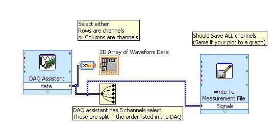
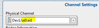
I downloaded the program entry OR bridge-continues and tries to modify it slightly to allow several Wheatstone bridges to connect. Currently, it has the ability to connect to a single channel but don't not to acquire information from several channels simultaneously. All information regarding the shunt calibration, bridge information and waveform graphic output remains the same. Ideally, the program displays the greatest value in the final waveform graph, but it is fine if it shows separate graphs for each of the two entrances. I was playing with it without much luck though if I start from scratch and you use the DAQ assistant, I'm able to get information without penalty. Any help would be appreciated.
In fact you are 99.99% of the way.
You just need to 4 characters
The name filtering on this control is even properly defined to allow multiple selections and just shift click on the second channel
-
Reading and saving data of two serial ports
Hi, I googled similar questions in the forum, but I don't have an answer for my problem so I'm posting it here.
I would read and record data of two balances throgh serial ports. I have a drop down menu in VI, I can choose the availabe ports on my pc. But it is still only one that works. So I only get one data scales them.
I usually get to choose 6 ports, but only one of them works. So I'm wondering if this is something that has to do with my pc or the VI?
I've attached a screenshot of my VI.
Thank you =)
-
PXI-5122 and PXI-6259 read 2 channels simultaneously
There is a single PXI-5122 digitizer card and a PXI-6259 DAQ card in our PXI system, we use Labview and TestStand (model Batch) to test the multiplication Board simultaneously, sometimes up to 8 boards are tested. We have some problems, such as the results of the tests is not reliable and sometimes blocking of Labview. Everything works fine when test single board. Thus, we feel that multiply causing this problem of acquisition of string data. It's great, if someone has the same problem and we can share the knowledge. My question is as follows:
1. If two channels have been configured, read the two channel simultaneous cause blocking of the system or data damaged?
"lu niScope WDT.vi" is reentrant, we can use two Subvi to call the "niScope Read WDT.vi' access the two channels simultaneously.
2. If we set up a channel in another channel is reading the data, this situation will cause the search system or corrupt data.
Concerning
Samuel
Hi Samuel,.
You shouldn't have any difficulty to read several channels on your 5122 or between your 5122 and your 6259. You receive an error message when your test is blocked? What happens when your test is not reliable? Are you incorrect data and if so what is the data vs expected data acquired? You should be able to set both your channels in a single task, which would be using a read niScope WDT.vi to be used by the device. You are working from example or have you developed your own code? What version of the driver NOR Scope and NI-DAQmx driver do you use? You can find the driver version number in the measurement and Automation Explorer under the software section.
What kind of test are you running? Your PXI chassis is controlled by a computer or by an on-board controller? Evolution of the rate of acquisition has an effect on your program?
-
Hello!
I have a problem regarding the acquisition of data from multiple channels. I get a channel data in time, but when I try to do a similar code to get data from another channel, it will not work. This can be done with the DAQ assistant, but I want to avoid this solution, because it slows down the program a little.
The snapshot accessory show how this is done for 1 channel. Can I use a similar program for the acquisition of several channels?
Thanks for your help.
You must only specify several channels in your task - i.e. Dev1\ai0:1 and replace the DAQmx Read N channels. Go to the task in MAX and click the channels button Add. Follow the directions.
-
Hello
I have a power meter which provide the USB driver and a Labview program to get the data and NI USB-6221. The project I am currently working on the needs of:
1 acquire two signals (inputs of simple tension), pressure frequency KHz
2. acquire a flow signal, the output signal is 0 to 5V pulse, each pulse means 0.4 ml volume. So I use a voltage inflows to count impulses in certain period of time (in this case, 1 S) for water flow. ; KHz sampling frequency and the 1 Hz update rate
3. acquire a signal of engine speed. The output signal is pulse square wave whose frequency is related to the speed. I use a REIT port to measure the frequency. Sampling rate: Auto
4 give output voltage sine or square wave, I use AO do that.output rate: Auto
5 acquiring by VISA electricity meter data. Data update rate: every 50ms
Currently, all the 5 tasks work well separately. But when I put them together, some signals are beginning to hang, for example, pressure signals sometimes give nothing.
Another problem is the data record. I programmed the VI in such a way that whenever I press the button 'save start', he begins to record data and save them in a .cvs file. For some reason, I always get only the data in the first table. Coult someone help me? I download my code as follows
Hello
What I meant by open, write, close. For any type of file you are using.
Open the file, which produces a reference, then put the mention in a registry to offset.
Write data, using the function write (for this type of file) and the reference.
When you are finished, close the file reference.
Writing in the spreadsheet opens, written, close all at once. It is very good for this type of application.
***
The issue of the loop is more general. I would like to say first of all, I want to say that since each loop works on its own, it is own VI, and that this program has put all this into a single VI, which has a method to solve the problem is to disable all the loops and allow them one at a time to see if there is a culprit responsible for.
Using multiple loops executes the code at the same time, and some loops would be cycle faster than others, especially if some of them are loops just as they are.
Communication between the loops is a test to the address if necessary.
Running all these signals through different loops DAQ must also be examined. Don't know what questions are for read and write somewhat randomly in the channels.
-
How to read and scale of multiple analog input channels
Hello
I'm reading the data of several types of sensors, with readings of 4-20mA. What I'm trying to do, is have a pressure transducer, a flow meter and a RTD sensor all connected on channels 1, 2 and 3 of my cDAQ using DAQmx. After channels are put on the scale, I need to see all the data in a chart of the wave with the scales on each side, identification of pressure, temperature and flow. Finally, I need to write that data to a text file. TDMS is fine, but for now, I'm working with a CSV file.
So far, I got my VI to read the data channel and the data on the scale correctly. I'm also writing to the file works properly. However, when I try to change the second channel, nothing happens or I get an error. Can someone help me on this? I have experience to come Monday to it so Im a little short of time. Ive fixed this Ive got so far (Ive got several versions of this VI trying to do this in various ways).
With respect to the accuracy of the readings for channel 0, Ive been using a deadweight Tester and a manometer calibrated to see readings. So far, these are correct, and I was able to calibrate other gauges with this interface.
Way easier and more foolproof that I found to do this is to set up several channels using an Express VI (DAQ assistant) and then made a right click on the object of block diagram and 'open the fron Panel '. Click OK to the warning and you will be pressented with an example of a multi-channel configuration.
As to the best way to get 90% it when learning DAQ configuration...
-
simultaneous reading and writing on a PDM file
I found similar discussions on here, but none that satisfied my problem. I'm running several loops within a vi, which writes data in a permanently .tdms file. Another loop to finish its task from the start in a test, and I want to transition this loop so that it accesses the file writing and started writing on a network. It also enables me to check that the data is being stored in the file and that it is corrupt.
I started with just the basics, but when I pass the second loop to read the file that is is always written off mistakes, saying that she met at the end of the file. It does if I put the count 1, -1 or anything in between. It illuminates, however, the end of the file output.
I have the entry in the file tdms on PDM read wired to a local variable, just as I do writing PDM, they all have both read the same thing and I get an iterations of a data value of the reading, so, apparently, file access is no problem. And I have to someone who cringed to local variables, ensure that reading and writing are not activated until the local variable is updated.
Try to set the "group name" entry on «TDMS read» If you write more than one group, you can use "View the contents of the DDHN" in order to get a list of groups.
Herbert
-
The display and recording time elapsed during the reading of the instrument
I've been programming Labview for a total of two days so please bear with my inexperience. I have a 9201 module that takes a reading of the voltage and it is plotted on a graph. I click on a Boolean switch and the graph starts playback and recording data every 3 seconds. When I click on that same switch I would like to start a clock. Then once the button is clicked once again I need to stop the clock and save time. I tried to use the elapsed timer function but can not understand how to operate inside my main while loop. I don't know if I need to use a subvi or something different all together. I enclose my any project that could make the issue easier to understand. Thanks in advance for any help.
I changed your code (personally I him would not have made it, but I don't want too many changes in your code because you are a beginner in LabVIEW!).
-Now, there are 2 loops: 1 bow for the acquisition (looped) and 1 loop for user interface operations (while loop + event structure: it is a very powerful structure in LabVIEW and you should take a look at a few examples to understand how it works)
-You will find a registry to offset used by loop acquisition: I explain what it is in the diagram...
-I gave you a VI that is almost the same as 'out of time' Express VI: maybe it will be interesting to try too understand that when you get more experience in LabVIEW (you will understand 'functional global variables' and "reentrancy execution": these 2 animals are used by 'elapsed time' Express VI (but also by the VI I've included, and which is almost the same thing))
Note that I have shown the solution to 1 of the 4 graphs: you will need to do the same for the other 3. You also need to code elapsed time saving.
Once again, the solution I gave you is very far from perfection, but with 2 days of practice of LabVIEW, it would be too complicated to explain the different architectures and the means of communication between the loops etc...
-
How to read / write several channels at a time target real PXI with a Board of 6259
On a PXI real-time target, I was able to access more of a channel at a time. The attached example illustrates the problem, when the second analog read occurs, I get a 'resource is reserved error '. It is my first challenge in real time and do not know how to proceed. In the end, I need to read three channels of analog input and analog output channel in the loop in real time. Thanks for any help.
Yes. You need to put the two analog inputs in a single task. There is only a single clock for reading of the analog inputs. If you use it for a task, this clock is reserved and the other task cannot use it.
That means connecting it to an analog output channel must do with it? If the ai0 is not connected to anything, why you try to read it?
The reason why you see something on this channel, it is that you see the residual value in reading the other analog input channel. When you have an open circuit, the amplifier may not load or unload by another value, if you see a ghost of the other channel. The entry for the land of analog unused thread and you'll see that the reading is zero or very close.
Maybe you are looking for
-
L755 satellite internet connection drops but stilll connected to the network
Hello I hope one of you can help me. I have a laptop 13 q Satellite L755 nice for a year and a half. My problem is that I surf the net and suddenly my internet connection drops down. On Firefox or IE, I have a message with a triangular signal yellow
-
No update firmware 6.4.0V.1 on 32RL838F
Hello I have a similar problem as some of the previous posters here on the forum.I am the owner of 32RL838F with the 6.0.0H.1 firmware, October 1, 2011. In this document:063E4A HTTPS://PORTALCP.TOSHIBA-TRO.DE/DOCUMENTS/10781/5BAFB15D-5E41-46B9-97D2-5
-
pique answers don't not again me oops then shut it down tab is displayed
I've been playing Spades threw live windows for over a week now and from tonite its saying Oops! close the tab and restart but etime that I do what it says exactly the same thing. what I can do.
-
I need a solution for the server connection error: 403. I know that there is a work around.
-
How to display the menu bar in Windows Explorer?
I use Intel Core i5-3470 CPU @ 3.20 GHz, 8, 0 GB of RAM, Intel HD graphics cardMS Windows 7 Home Premium v. 6.1 64-bit SP1I have Kaspersky Internet Security in 2014, and I Google Talk, Skype and Memeo Backup Premium Pro running in the background. I t