writing multiple modbus registers
Hello
I am communicating to my labview program controller using modbus RTU and the controller has 16 bits in modbus registers.
To send the float as '1.23' values, I write two registers to store the hex value that number in comma floating 32 bits.
I use the modbus driver provided to this end by labview and use labview 8.2.1
I have the following doubts in this regard.
- The "Modbus master series query. VI"has the command Modbus that records an entry which I use to set the registry values in the controller unit modbus. To send the above, mentioned in floating-point registers 501 and 502 (contains the full value of the PID parameters), use the same vi, whose value should be registered first... is the high or low, to be written to 501 and 502.
- The function code to write to multiple records in the modbus driver is 16. But my document that is specific to the Controller explained in the section "writing to multiple records" with the code of function like 10. And I see that feature codes 'writing in the single register' as well as the driver for modbus producing the same type of message frame as discussed in the document. But I see no similarity in the function "write multiple registers" in the document and the modbus labview driver.
- "Even if I write records 501 and 502 one after another will use"write in the single register"function code when these registries implement floating-point single using 2 registers ' 16 - bit '. If this method is possible, then I will come and do it the same way I did it for the entry in the single register. While writing data in records one after the other with a gap between the two as small as 4 ms scriptures do good?
I suspect a confusion between 16 decimal and hexadecimal 10
Two successive registry entries are not equivalent to a double entry: during the period between the two scripts your controller will be loaded with a false parameter. It is perhaps not necessarily a source of problems. It depends on your application. Writing the MSB should first reduce the problem.
The order of Hi-Lo is dependent on the machine control. Some use the Big Endian, other Little Endian. But this choice should assign unique register values (U16) as well.
If it is not documented, you should read the records and see if the result is logical. If this is not the case, invert the byte order and verify that the problem is resolved. Good luck
Also, I assume that you know how to use the conversion feature to convert a single (32-bit float) 2 U16?
Tags: NI Software
Similar Questions
-
Modbus, writing in the registers by PID regulator
Hello
Can you please help... I'm new here
I try to use a registry read, send the value to a PID vi, then write in a register.
I've attached an example of using a temperature regulator.
I get errors whenever I try to connect using clusters, clusters, etc..
My material and comms are all good, I have values and all gauges reading ok, but it seems I can't work on how to manipulate the data through a vi of PID.
Your help is very appreciated.
Thank you
1 rearrange your functions so that your reading of data occurs before your writing of data. You can do 1 2 3 4. Right now your code run step 3 before step 1 and impossible to know where should go steps 2 and 4.
2. your writing log has an entry called registry where your worth is going. There is an entrance to U16. Your PID provides a DBL. You need to read the manual of the device know how to code the PID output floating point number into an integer. It may be a simple by multiplying by a factor of scale and he rounded to an integer.
3. your Modbus Read is for several records. You will get a table 1 d of readings, but it will not be 1 element. You can use the table to Index, and then together with setpoiint wire to feed in the gauge of multi-aiguille. Since you data will be an integer U16, you may need to perform a scaling to convert an integer in all that but it represents the temperature.

4. don't forget that you must connect your process in the PID function value.
-
Linking a Varable shared several MODBUS registers
A simple question, but can't seem to find an answer:
I have a library project with a configuration of server i/o MODBUS series. In this library, I have several shared variables that are related to the registers on the remote device via the MODBUS Protocol, and this works very well if every variable is bound to read a single register (for example Modbus1\D400001). What is the proper syntax to bind a shared variable that is unique in several consecutive registers? If I put the type of shared in the "table of UInt32" Variable can I clarify something in the direction of Modbus1\D400001-D400100? So far, this doesn't seem to work, or at least doesn't have anything that is displayed when creating indicator table and linking of this share to the indicator variable. Thank you
-David
Sorry, I forgot to mention that it is version 9.0.1 LabVIEW with the DSC module.
Hi Underscore_c,
Take a look at this help document:
http://zone.NI.com/reference/en-XX/help/371618E-01/lvmve/dsc_modbus_using/
This document should also be in your LabVIEW help. You will notice that you can call a table of records by prefixing the address of 'A'.
For example,.
A400008L8 is an array of values of length 8.
There is an example called "Data type Extension Modbus" which should help you get started in the right direction.
Dave T.
-
Hi all
I have been more manuals/son using the Modbus Library to communicate through series. However, I'm not sure what exactly I am doing wrong. If I use a program like Modbus Poll and send 02 03 00 02 00 02 65 F8 I get a response: 02 03 04 39 20 90 D5 F9 3F. Looking at the manual for the device that I'm communicating with (a pressure transmitter), the application is in the following format:
02 - address
03 - function
00 - StAdd H
02 StAdd L
00 - reg #:
02 # reg L
65 CRC16 L
F8 - H CRC16
The answer is in this format:
02 - address
03 - function
04. # of bytes
39 data:
20 - data L
3F - data:
90 data L
D5 - L CRC16
F9 - H CRC16
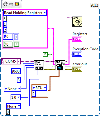
So, in LabVIEW, this is how I have it Setup:
I put the 'Start' address to 1 because I have read, there must be in LabVIEW 1 less than what the actual starting address is (n - 1). I expect the same reply as above using Modbus Poll. In the diagram above, I get the following registers, starting at index 0: 256, 661, 63490 33538
Obviously the answer is not in hexadecimal as above, but it is nowhere near what it should be.
Thanks for the help!
-
Cluster vs multiple Shift Registers
I had a question about good coding practices.
Say you have several elements (numeric values, strings,... whatever) you need to iterate between the loops.
Is it better to make a registry change for each item?
Or cluster, and then move the cluster to a single shift register?It is faster than the other? Or better/worse for another reason?
Cory,
Yes. and no.
I usually create a large cluster of typedef I call indicators and flags (InF). I put most of the things that need to be passed around with that. The cluster of error, the State enum and large data tables are usually in separate shift registers. Table L: shift registers and data are at the top of the loop and error and SRs of the State are at the bottom. Most of the code goes between them. Given the help of bundle/Unbundle documents name to which the data is used in a case. The InF cluster is usually not displayed on the Panel before and may exist only in a Subvi to save space of block diagram. The data are unbundled indicators as needed for display to the user.
If you have a situation where speed is concerned, separate data that must be processed everything quickly and optimize for that. Strings and arrays within the cluster probably cause some memory interesting distribution issues since they change size, that can be an argument in favour of that separates them.
Lynn
-
Hello Forums or
This is my first post on this forum and I've been using labview for about 8 months now
I have a problem about writing data in the modbus registers through a server of e/s defined as a slave modbus for my hardware 9074. Once I finished the project of construction and deployment of the variables and by following the instructions here , he reports no results but a row of zeros. I have the DSM nor opened and configuration modbus master to see whether the data is actually read or written on the respective sides that give the same line of zeros so. What I am actually trying to write is a single-precision floating data table. The registers are structured F40000-F46534 runs from 10 items or have them for range AF40001L1-AF46534L1 of the AF40001L10 point where it's an array of length 10. (Referenced beaches here)
I know 1 thing for you, the modbus connection works and is ready for data requests, I tested cela NI DSM and set manually the data for and received my master.
System and project specifications
Windows 7 operating system
LabVIEW edition development system complete 2011
No module Labview DSC, but I use the real time such referenced by one of the documents
This project is an application in real time with fpga mode (and not scan interface)
The master and the slave are the same network and subnet
Connection Modbus type: TCP
9074 compact slots rio 8
9234 module x 3
module 9221 x 1
9472 module x 1
Engine service Variable shared running on windows os and rtos system
Used this guide to learn more about the Protocol modbus, as I have searched all over the internet to learn more about modbus
I already have software Modbus IO Server installed on the crio thanks to max or 1.8 for NI RIO 4.0 version
file attachment (s)
Image of software specifications Crio
Image of data written in scheme-block rt variable
Short version of the problem: why is the e/s no variable writes in with the converted correctly data?
Okay, Yes, it's that I was the one proposed. Regarding the news of the error, if you look at the bottom of your image to DSM, you see a little commfail and an error code, but it seems that those are OK.
The only thing I can think is that DSM (or another function) is written for a range of values that includes 400004. I suggest you to put into service 4-going to a range of 3. 3 s are entered only (perspective control), then you can be sure that the master is not trampling on the data. Once you have checked that, look at DSM and any other code running to make sure q EU not accidentally write 0s to the same reg.
-
Performance of Modbus using DSC static Variables
I'm fairly new to using Modbus with LabVIEW. On some dozens tools and APIs that can be used for a project, I train, I decided to try using an alias of shared Variables in Modbus registers in the project, which is a tool of DSC. It seemed like a smart to go way. I used Variables shared in the past, however, and I am aware of some of the questions that surround them, especially when the number of them begins to increase. I will have only about 120 variables, so I don't think that's not too bad, but I'm getting a little worried...
The way I started to do this was to create a new shared variable for each data point. What I have noticed since then is that there is a mechanism to process multiple records at once using a table of values. (Unfortunately, even if I wanted to use the table method, I probably couldn't.) Modbus points that I am interfacing are for a custom device and the programmer does not disturb the consecutive use records...) But anyway, I was wondering what might be performance issues that surround this API.
I guess:
(1) all caveates of shared variables apply. These are really shared variables, but only DSC taught the engine of the SV to go read. Is this fair?And I wonder:
(2) there is no improvement in performance for reading a table of variables consecutive rather than reading each variable individually?
(3) there performance above problems what shared variables have normally when you use Modbus specifically? (E.g. how many times can you read a few hundred points of the device even Modbus?)
Thank you
DaveT
Hi Dave,.
Thanks for your good questions!
(1) you are right that the caveates of shared variables apply. Generally, the major issues (conditions of race etc.) are not met because these variables are generally used as I/O.
(2) with a large number of shared variables that are located on separate machines, it is best to use a table. However, with 120 variables read consecutively will not affect your overall performance, especially if you don't need to read everything at the same time.
(3) overall, there is no any concerns of performance outside normal common variable concerns. Modbus and DSC are designed to be efficient and do a good job to maximize performance for you.
I hope this helps.
Best regards
Anna L
-
SDC RTU Modbus - cannot specify the type of query for each register address
Hi, it's Jose.
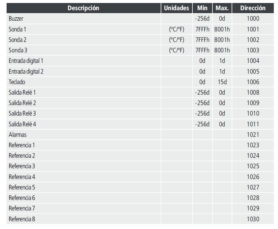
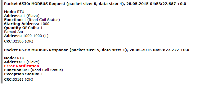
I have try the DSC module to connect with a temperature module, but this, does not meet the MODBUS registers addresses, for example to read the temperature, I should ask a 0 x 03 at address 1001.
But for DSC for a request of 0x03, it expects to addresses like 4000, so since 1000 addresses belongs to coils, SDC makes a request of 0x01
My thermometer has even coils register.
Is there a way to force the DSC to make specific requests?
Thank you and best regards
What happens if you enter the numbers as 400001 401001 or simply?
Also try to only 1.
The current Protocol does not transmit the prefix number which he calls a coil (1) or (4) record keeping, (3) registry entry. (I mixed up to the top of the last two is possible).
So the device describing the registry with the wrong group of addresses, may not matter. You just lie to LabVIEW to tell him where he thinks is it supposed to be.
-
Several Modbus with shared serial port
I know that Lookout lets do you cool things like have several protocols series that share the same serial port hardware.
I asked where I might like Lookout to simulate a network of Modbus Devices for some tests. In this case, I want to implement multiple Modbus slave, all with different node addresses Modbus objects and have all listen to the same serial port. Would this be possible? Each received Modbus message will include the number of slaves in there. Multiple objects can listen on port and only the selected one respond?
Thank you
Max
Yes, slave modbus Lookout can work this way.
But the ethernet mode does not support.
-
I write the values for my meter with modbus/TCP and the set point is a float on 2 registers.
Documentation, says this:
Floating point parameters are 4 bytes long and are mapped to two consecutive Modbus
registers. The floats are single precision IEEE (1 sign bit, exponent fraction of 23 bits and 8-bit) format. The
first register contains 16 32 bits, the second register contains bit 15-0.The modbus library sends unsigned words, so how I break a float in two words, corresponding to the above requirements.
Thank you!
-
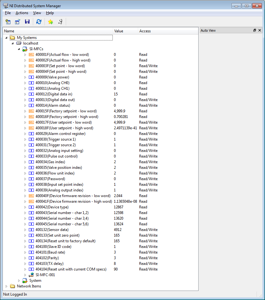
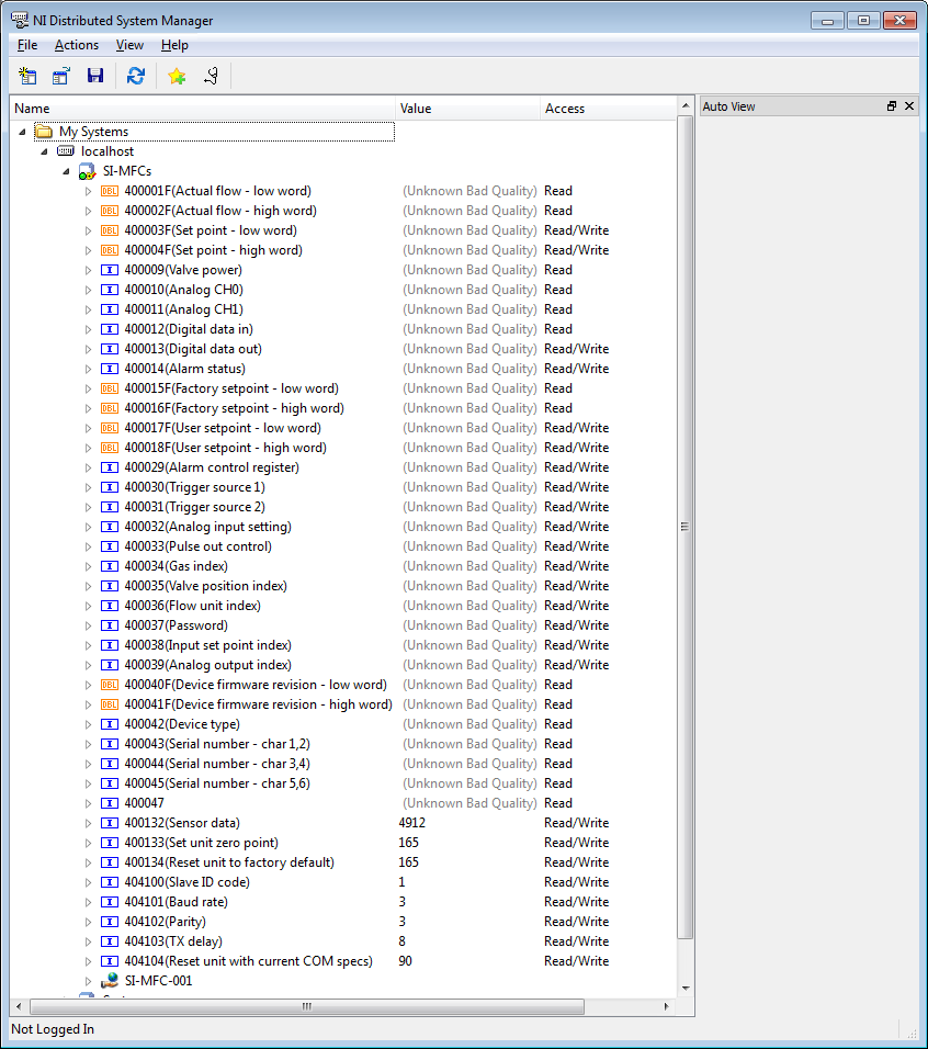
Display problems of some records in the distribution manager
I use the Distributed System Manager to communicate with my Sierra Instruments MFC. Most of the time, I am able to read the values of its MODBUS registers. However, there are certain records that the DSM does not seem to be able to read correctly.
In the 1st screenshot, I show a case of work.
Note the displayed values 400043 by 400045 records are the decimal equivalent characters ASCII coded 16-bit (hex) and when combined give the serial number of the CMF. So in my current example:
400043 = 12598 == 0 x 3136 == "16".
400044 = 13620 == 0 x 3534 == '54.
400045 = 13624 == 0 x 3538 == '58.
Serial No. = 165458
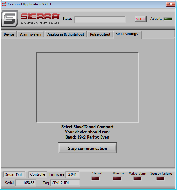
Registers 400047 400051 through each contain 16-bit ASCII encoded characters when combined give the ID of the tag of the CMF. However, when I read the 1st of these registers, then I get an error that also live by reading all the previous registers (I dunno why...), as shown below:
I know that the info for the ID of the tag is there as it appears in the GUI of the Sierra Instrument:
Any ideas?
-
Can I send several CAN messages through a table?
I am very new to this, so bear with me. I am writing for a CAN bus line and we would like to send several messages through the feature of writing through the API. But when I create the control for data is just a 1-d array. I'm able to do a multiple choice of messages?
Hello
For new people, CAN bus, the NI-CAN driver brings examples for nearly every use case. Version 2.4 or later driver has the writing of multiple writing multiple images to those functions.
An example is currently available for LabVIEW, CVI, and VC/VBasic called CAN transmit several.
DirkW
-
you have to have free space, or your files will automatically separate?
I have about an 80 gigabyte and I want to share it at halfway but its full, so I was wondering if windows will automatically share files
Your question is not particularly clear.
Windows will only save a file on a single path then if the Act of writing a large file will fill a particular drive that the write will fail completely with a lack of space error.
When writing multiple files to a removable device, it can request a change to the device when it is full.
It is not generally recommended to fill out a capacity HARD drive as standard household tasks will not work. You should always have at least 15% of free space on a disk partition.
-
Modbus write multiple registers incorrect version
I use NI Modbus.llb, found on the site OR somewhere...
Now, I found the broken wires by calling vi because MB series Master query write multiple registers (poly) .vi has an output at least (probably written content, read later... check...)
Where can I find the good .vi MB series Master query write multiple registers (poly)?
Thank you
It may also be that previous guys changed the Modbus function OR...
-
ComBox MODBUS - difficult to write in the registers of the S.R.I.W.
Hey guys,.
I'm talking to a UPS (ComBox XW +) via MODBUS TCP. I can read the values of read only registers very well, and they line up exactly what I see on the interface of the web page they have. However, when I try to write a particular register r/w, I get an error of the incompatibility of function (-538172 using modbus smithd API). Also, when I try to read the register R/W, I always get the value 65535. This leads me to believe there something wrong with my configuration of device, but just in case, I thought that I would make sure that I wasn't doing anything weird in the code. Please the the image of the block diagram, as well as the manual that I use for the device in the attachment.
There is a small note MODBUS online as well:
http://solar.Schneider-Electric.com/wp-content/uploads/2014/04/conext-TL-using-Modbus-application-No...Hey Thomas!
Thanks for your help, however, this link is not available more when I try to open it.
In any case, this problem is resolved. I was just writing the bad slave ID! The other slave was present on the network, but it is card MODBUS is completely different, that's why I was seeing these weird values.
Maybe you are looking for
-
Satellite 2450 S203: registration issue
I am the owner of a Satellite 2450 S203 and I can't find it on the recording of "my computer"? any idea?
-
It was working fine until I did a few midifications to the admin ACCT. I think I clicked somewhere by mistake
-
Hello I don't remember the bios password, I get error 70847527 after typing the password 3. Thank you
-
How can I change the "format" of an e-mail image to move in my photo gallery? I need to make changes before that I can print.
-
Why see a horizontal line momentarily across my screen.
I noticed a horizontal line momentarily on my laptop HP Envy, which has only 90 days I rhave a screen with Windows start-up 8.1 and have recently received an update from the Intel driver. GPU Intel(r) HD 4600