acquisition system
Hello, everyone.
I use labview 8.2. I'm programming an acquisition system, which with 8 channels, both important channels is sound pressure lever and wind speed, I use a graph to display set as an attachment. The x axis are the speed of the wind, it is divided into several bins, when new data are acquired (1 Hz), depend on the value of the wind speed and pressure lever; sound it will be filled in tubs. When each bin contains enough data, I can stop the acquisition. Sound pressure lever signal and the signal of wind speed both are voltage.
Thank you very much
Fay
Tags: NI Software
Similar Questions
-
Exchanging USB data acquisition systems
Hello
I'm looking to use the same program in labelled while sharing the acquisition system of USB-6210 data with the same program. I use labeled 8.5.1 and have a voltage reading program. What I find, however, is that the .vi program does not seem to acquire on the software side, when I disconnect the USB-6210 I use and plug in another, but the same hardware system model. The Green LED on the material will begin to Flash, but there is no entry in the charts of the program. To measure the voltage, I use the function block "DAQ Assistant" to connect to the analog channels in this system. To work around this problem, change the DAQ Assistant function for the device interchanging at work (delete and use the wizard to generate a new DAQ Assistant). It's quite heavy but doable, however, the hope is to apply this program and equipment to several sites, each with their own system of fittings. Is there a way to exchange the hardware systems, but keep the same program so that it might be a way around this? I also used the Application builder to generate a stand-alone program for it but the same problem occurs. Is there any recommendations for multiple devices, or am I missing something? Thank you very much.
Whenever you connect a new device, it gets its own device ID.
from Dev1, Dev2 etc..
So either rename in solution of measurement and of Automattion (MAX) Explorer or use another parameter in the daq assistant.
-
choice of the model of design for data acquisition system
Hi all
I have a problem on the selection of the model design / architecture for a data acquisition system.
Here are the details of the desired system:
There are data acquisition hardware and I need to use by looking at the settings on the user interface.
the period of data acquisition, channel list to analyze must be selected on the user interface. In addition, there are many interactions with the user interface. for example if the user selects a channel to add scanlist, I need to activate and make it visible to others on the user interface.
When the user completes the channel selection, then he will press the button to start the data acquisition. Then, I also need to show the values scanned on a graph in real time and save them in a txt file.
I know that I can not use producer consumer model here. because the data acquisition loop should wait for the settings to scan channels. and it works on a given period by the user. If the loop of user interface makes higher then loop (loop data acquisition) of consumption. This means that queue will be bigger, larger. If I use notifier this will be some data loss comes from the user interface.
y at - it an idea about it? is there any model of design suitable for this case?
Thanks in advance
Best regards
Veli BAYAR
Software for embedded systems and hardware engineer
Veli,
I recommend the model producer/consumer with some modifications.
You might need three loops. I can't tell for sure from your brief description.
The loop of the User Interface responds to the user for configuration entries and start/stop of acquisition. The parameters and commands are passed to the Data Acquisition loop via a queue. In this loop is a machine States that slowed, Configuration, Acquisition and stop States (and perhaps others). The data is sent to the processing loop through another line. The processing loop performs any data processing, displays the data from the user, and records to file. A registrant can be used to send the Stop command or stop the loop of the UI for other loops. If the amount of treatment is minimal and the time of writing files are not too long, the functions of processing loop might be able to happen in the case of the UI loop timeout structure of the event. This makes things a little easier, but is not as flexible when changes need to be made.
I'm not sure that there is a type of design for this exact configuration, but it is essentially a combination of the models Design of producer/consumer (data) and producer/consumer (events).
Lynn
-
I'm designing a new data acquisition system. I just need some advice on how to design a system properly to acquire data accurately without too much exaggeration.
During the event of 100 ms, we would capture four pressure curves (event unique, non-periodic) and voltage of several spikes (indicator time to specific event). We would use a charge amplifier to amplify the signal from pressure sensors.
Can someone point me in the direction of some books useful, tips, rules, basic Web sites, theorems, etc. to design a system for the acquisition of data including but not limited to, the following topics?
Sampling frequency:
What criteria should be used to determine the frequency of sampling? As the waveforms will not periodic, I think not that the Nyquist theorem applies. Are there any general rules in this case?
Voltage range / Amplification:
How much I amplify my signals? Our specifications define a scheduled pressure, the maximum value, maximum pressure, that the system should handle and tolerances. How many voltage range must be a signal medium or maximum signal?
Data bits:
How can I determine how many bits of data (and the distinct values so) I need to acquire the characteristics of my curves of pressure with accuracy?
Hi Steven,
I have a few PowerPoint slides (attached) of the hands on Session of the week DAQ last OR that give an overview of these three specific themes. They were meant to be more than an auxiliary to the presentation, so they do not have too much information, but the images that seem to be always helpful (there are animations so you will have to go through the slides in presentation mode).
Sampling frequency:
It really depends on what you're trying to measure. You're right that Nyquist frequency applies that periodic signals (you won't have aliasing if the signal is not periodic), but the sampling rate is always very important depending on how much you care to characterize the shape of your signal.
If the signal changes rapidly, you will want to ensure that you are sampling quickly enough to acquire enough samples along the transition to be able to characterise the dash (if this is important to you). On the other side of things, if you're sampling too slowly, it would be possible to completely miss a pulse if its duration is less than the period of your sample clock.
Voltage range / Amplification:
They are definitely together. To optimize the resolution of the ADC, you want to choose an amplifier that fills the whole range of ADC. Many DAQ cards have integrated amplifier and provides several beaches available (although in DAQmx the user specifies just coming available they want).
Bits of data (aka resolution):
It doesn't tell you the number of discrete levels available that you can represent the entire range of data acquisition card. However, this value is different from the precision due to the error of gain/offset, nonlinearities in CDA and noise. If you are interested to determine the accuracy of your measurements (which is quite common), you should check the specs of the device and look for the specification of absolute accuracy.
So in general, I think that you need to understand what are the exactly your needs before selecting equipment. Are what information you trying to determine from your curves of pressure? Is the digital signals voltage just spikes that must be timestamped? What this timestamp would be compared to?
Best regards
-
Hello
I am completely new to LABVIEW software.
I learn a LABVIEW code existing my pressure (attached) acquisition system which has the path of data as follows: pressure transducer Validyne--> Validyne CD280 - Dual--> SCB - 68--> PCI - 6024E--> LABVIEW and I have a few question:
1. How does the complete system of the transducer to the LABVIEW work? That is, if we apply the pressure of the transducer, it will change the resistance of the probe then...?
2. How can I find the equation that expresses the relationship between the pressure and the tension to the keys of the Validyne double-CD280 in the LABVIEW?
3. If I want to do the probe calibration, what are steps?
Thank you
You did not include most of the subVIs.
-
How to stop an acquisition continues in producer/consumer
Hello
I'm trying to use producer/consumer to control 'Start' and 'Stop' to my continuous data acquisition system. I can start the acquisition process successfully, but I can't stop it botton 'Stop '.
I enclose my simplified VI. Can anyone help to have a look and tell me what is the problem here?
Thank you
Bing
As I said before, use a notification utility and manage the expiration time. I used a select statement with timeout? Optional Boolean. If a time-out of events, use the previous value. If we got a notification, use this value.

-
Calendar for the acquisition of data on the USB-6212
I am putting together a sound teaching laboratory. The basic idea is to send a pulse signal that powers a speaker, and then the acoustic signal travels down a waveguide where it is measured with a microphone and sent to a data acquisition. One of the important things here is that it is possible to measure the time of propagation of sound waves, so I need for data collection to occur at a time determined with reference to the sound output pulse. I tried with a sound card, but there are number of milliseconds of random jitter between the writing and the reading of the sound card.
So, I was watching the USB-6212. On paper it seems ideal: 2 outputs and lots of inputs. What I understand, it is possible to trigger analog outputs and data entered so that there is no jitter synchronization between them. The only question is this: I was thinking about using 2 analog inputs: a reference which collects through a microphone/speaker system to serve a normalization to the second chain that collects through waveguide (see diagram). The thing is that I need the "timing" on the 2 analog to be consistent and a jitter free so that it is possible to compare the phase of the signals that I collect. This will be possible using this data acquisition system, given that the ADC is multiplexed between the channels? There will be a delay between channels 2 and if so it will be known and deterministic?
Thanks for your help...
Ben
Hi Ben,
Cool application! To answer your question-Yes, there is a delay, and it is deterministic. Something to note about the 6212 is that your rate of multiplexing will be determined by the clock to convert. The clock to convert will operate at the faster pace of the device more 10us *. In the case of the 6212, with Max sampling rate of 400kS/s (aggregation), your pulse will produce each ((1/400,000) 12.5us + 10).
* 12.5us converts to 80 kHz, so at that point there, convert clock it simply runs at 1 /(aggregate rate). So to sum this up:
From 0 to 80 kHz: there is a lag multiplexing 12.5us
From 80 to 400: there is a shift of /(aggregate rate) 1
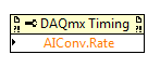
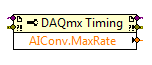
In addition, you can also set this rate through the DAQmx driver. "You can just use a property DAQmx Timing node' more' converted ' rate (or rate Maximum to determine the max).
If it's a problem, I advise to use a device with simultaneous sampling - let me know if you have any other questions. Take care!
-
Acquisition of images using PCI-1426 and Camera Link Camera
Hello
I am writing a program to capture images of a Camera Link camera via the PCI 1426 acquisition card in LabVIEW. The problem that I am facing is that I am unable to find the correct controls in the functions palette to start the image capture. Could someone tell me please how much control I'm supposed to use?
I've worked on similar request sometimes back, I used IEEE 1394 camera, so once I found the correct block diagram controls I should be able to go from there.
Thanks in advance,
Sandeep
Hello Kristen,
Thanks for the suggestion. I was able to solve this problem. I think that was what was causing the problem I have LabVIEW 8.6 installed on my system and he had the Vision Acquisition System (VAS) 8.5.1. But, once I installed VAS 8.6 I saw the IMAQ in the functions palette.
I'm guessing that LabVIEW 8.6 does not recognize the toolboxes of previous versions.
Sandeep
-
Installation of bench beginner for the introduction of analog measures
Hello world
I'm looking to install a system to help make some simle measures. This configuration will be used only by me at my desk/Workbench to help me better understand some parts of machine, that I as well as various other hardware troubleshooting. The I want to be able to take common measures are: stress/strain, vibration, temperature, force, torque and movement.
At this stage, this project is on a small scale. I'm not running from PLC or using data in order to operate a plant. This configuration will be about just myself, my computer and a piece of equipment, I need to test.
I currently have one 6003 NOR for my use that would be preferable to use, but if I need a stronger DAQ so I can get to the need.
My main question is if I can get aqeuate with hardware DAQ 6003 and results if I would be able to condition enough signls accompaniment or if I need a DAQ with higher resoluion and a signal conditioner sufficient. My concern is whether or not I will be able to properly signals on status of piezoelectric sensors at vibration action. Is there a way to produce viable results, or I'll have to come back a more capable DAQ? I wish I could do an analysis of the frequency on trees engines operating normally at about 60 Hz. It would be nice if I had the Betacam to observe signals of up to 150-200 Hz at least. In my case I don't need extremely accurate results if I can go out with an afforable configuration more. I think that a level of trust of value p final (90%) will go well at this time.
I'm still quite new to data acquisition and signal conditioning. My purpose behind this, especially to learn how to take the right steps correctly more than I worry accurate results.
If someone could give me their thoughts about this I would be very grateful.
Thank you kindly,
James
James
I think you need to split the signal conditioning in data acquisition. I suggest you watch the series 7B Analog Devices and some of the imitators, for example Acromag.
http://www.analog.com/en/products/landing-pages/001/7B/7B-Series-Overview.html
Essentially, you choose a module specialized for each measure of your choice. The modules are isolated, at least reduce signal interference problems. Sensor excitation, e.g. for the strain gauges is provided on certain modules. You will need to study the performance of frequency to get the 200 Hz on some modules.
The modules plug in a motherboard that can then be connected to any data acquisition system that you like.
Or the versatile NI9219 can better meet your needs.
-
Connection cRio 9074 second port ethernet to another device via VISA
I'm trying to connect a DAQ Yokogawa system to a cRio 9074 via the second ethernet port. I activated the second ethernet port of the cRio with a static IP address on the same subnet as the data acquisition system. I installed the driver NI-VISA and NOR-SERIAL on the cRio. I can compile the code on the cRio and I'm sure that the code works when I connect to the acquisition of data to a PC. I get an error on the open VISA VI.
Am I missing something or is it not possible to connect the second ethernet port on the cRio in this way?
Thank you
Thank you for your response. I found the same information that you provide, but decided to give it a try.
A few minutes ago, I was able to perform communication between the cRio 2nd access Ethernet DAQ Yokogawa. I managed to do it using the VISA controls. To communicate with the host PC, I get the information of the DAQ with the cRIO as described above and then use shared variables to publish data on the network connected through the first ethernet port.
If anyone wants to reproduce it just to make sure that the two ethernet ports are configured with IP addresses on different subnets that are configured for TCP communication. If more details are to be simply send me a message.
Kind regards!
-
Siemens simatic wincc SCADA and LabView/Measurement Studio
Hi all
I am currently working on the design of wireless data acquisition system using materials. Input signals captured by wirelessDAQ NOR will appear eventually in WinCC from Siemens SCADA system.
Is there a way to make this configuration? I thought to is to develop software for the acquisition of data using LabView/Measurement Studio and link code to WinCC via Visual Basic (for example via DAQmx). Thanks for all your comments.
Hi kid_26,
I'm sorry.
It is the only option.
If you press the cost, write a VB6 to call DAQmx is an option.
Sincerely, Kate
-
How to 'book' an Ethernet cDAQ chassis based in software without using MAX?
I am using a cDAQ 9188 with Ethernet interface. It works fine, but the Setup is a little more than I like for end-users. Users are all first go to MAX and do make a connection. After that, users must 'reserve' the chassis to ensure access to it. This isn't a problem except that I still have to find a way to make the code G. I have rather not in my documentation would include a series of steps require that the user enter MAX whenever they want to turn on the system. I would have preferred it is comparable to a USB DAQ experience where it works.
All the examples there or suggest on properties, methods or screws to use for my situation?
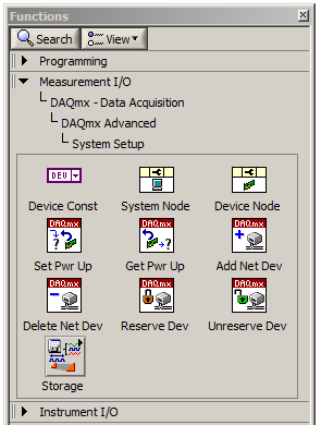
You'll want to use the DAQmx reserve Network Device.vi, under measures of e / s-> DAQmx--> DAQmx advanced-> configuration of the data acquisition system.
-
Do IMAQdx and NI GigE Vision 2.0 material support?
Hello
From my brief research, GigE Vision 2.0 has features very nice that I'm at the end which are not supported by previous GigE Vision 1.x standards:
- Compression on the side of the camera
- Timestamp and sync IEEE 1588 (PTP)
OR those taking? If not, are there any plans to add support in the near future?
Thank you!
Hi again,
Thanks for the extra frame.
Assuming that your only using the camera is saving JPEG images on the disk, and you are concerned about the performance of the acquisition system, I think that an IP camera might be a better choice. These cameras acquire images compressed, so you can very well save the direct-to-disk with no extra charge. This will save time and bandwidth of the network processor. The bandwidth would be nice because you could probably just run 6 cameras in a gigabit switch and connect to a port on the PXI chassis instead of several 8234 ports. This is possible because not only if bandwidth is reduced, but the IP cameras can use TCP and sharing bandwidth much more enjoyable that can cameras GigE vision. To save the raw images on the disk, you can use the IMAQdx VI "Get Image Data", which is a JPEG file that you can save directly to an IP camera.
Regarding the time stamp data, depends on the accuracy required. Since you recorded all the time after that image returned, is quite imprecise because it is not really correlate with the acquisition time. You might get a more exact time in two ways: record IMAQdx a CPU timestamp on receipt of driver that you can use (useful if the CPU is synchronized to GPS/NTP or similar) or you can use a timestamp saved in the image itself in the form of metadata (GigE Vision and IP cameras can do that). I think the Basler IP cameras can use NTP and testify to the time stamp for metadata EXIF JPEG images that you can extract. This mechanism is of course much more precise because it eliminates the delay/jitter of transmission at the time. If you have a few requirements of precision (microsec, milliseconds, seconds?), it would probably give a better idea of what your options are.
I suggest you take a look at the range of cameras from Basler IP. You can not control the parameters of the image directly in the IMAQdx driver (you must use their web interface, or write additional HTTP code), but once you have the configured device it will keep these settings.
http://www.baslerweb.com/en/products/network-cameras/IP-fixed-box-cameras
It is likely that the cameras will be more expensive that some cheaper GigE Vision cameras can be, but I suspect that you could save enough on other system costs will in this way to make up for it. In my opinion, doing compression JPEG on-the-fly with 350 + MB/sec of camera raw data could be difficult, unless you had a tough multi-core system.
Eric
-
Wavy jagged singal of 9237 at no load condition
Dear forum users and employees of OR,.
I would be grateful to you if you can solve my problem. My specimen is a simple piece of plastic 1 0.25 inch rectangular cross section with a length of 8 inches. I'm trying to measure the deformation (with the help of use general TML, Japan 1 mm gage length extensometer) in the sample by hanging dead in the sample weights. I am able to strain using the cDAQ 9178 chassis, NI 9237 module with accessory NI 9944 quarter bridge. For a given weight (so the applied load becomes a static), signal (output voltage) must remain constant independent of time. In addition, I also expect that when no load is present on the sample, the acquisition system data above should show constant, but the deformation of almost zero output over time. What is my problem only after offset removal and shunt calibrated correctly with the help of the wizard of LABView DAQ, the above data acquisition system shows a strain of output wavy stair of significant variation between maximum and minimum, even when the sample is at no load condition (the sample is simply placed on the table). In addition, even after loading the sample with a certain amount of dead weight, rather than get a constant signal, I always get a strain of output wavy stair (with more scale position zero load) over time. Please help me get a constant output signal for the data acquisition system above with and without load on the sample.
Thanking you
KSRKM
-
How about using labview vi of the filter and multiply vi to replace the analog filter and amplifier
Hi all
I use a data acquisition system to acquire a weak signal, it seems to a voltage amplifier and low-pass filter before the acquisition of data. I was wondering, if I use low-pass of the labview vi of the filter and multiply vi to process the signal picked up by DAQ, can I get the same effect as the analog low-pass filter and amp?
Thank you!
No!
1. any system of sampled data must be band including prior to sampling in order to avoid aliasing. It is impossible to remove aliasing after collection.
2. the resolution of the DAQ system will be so low that you'll very 'fat' scanning and you will lose a large part of the information in your signal.
Sorry, but you need to amplify and filter in the material before the data acquisition device for best results.
Lynn
Maybe you are looking for
-
Can I have the Profile Manager uses the name of the device used when the placement of placeholders?
Can I have the Profile Manager uses the name of the device used when the placement of placeholders? Currently, all get renamed 'iPad' when the device through DEP configuration.
-
I see that I can enter multiple URLS in the user.js file, but I can't know all the possible URLS I use because of the Moodle application. Is there an easier way for me to cut and paste?
-
Update my iPad iOS 9.2.1 now I can't update my apps
I just updated my iPad iOS 9.2.1 now it will not update my apps
-
Satellite L650-PSK1EA-06L02F - where are the specifications?
I'm looking to buy some RAM to upgrade for laptop computer to my father, but Toshiba support page lists absolutely nothing under specifications tab for this model.http://www.MyToshiba.com.au/support/computers/satellite/L650/psk1ea-06l02f/specificatio
-
HP m8120n os upgrade video card (geForce 7350LE
Hello, I own an hp m8120n operating system and you want to replace the video card (geForce 7350LE) - supplied with the system. The fan on the card is noisy and sometimes stops. I want a simple replacement reccomendation. I do not play. And if the fan