Characteristics of S3048-on switch open circuit
Hello
I am not able to find the list of the features of open circuit of the switch S3048-WE, I know he support Open - Flow1.3, except that I would like to know all the features of open circuit, it supports, as a match criterion, weather support netconf and so.
It should support all the features, I've not found anything to indicate otherwise.
Tags: Dell Switches
Similar Questions
-
DAQmx and SCXI-1160 with 'DAQmx switch Open Relays.vi '.
Hello
I use DAQmx to pass the baton on a map of SPDT 16 SCXI-1160. When I run the 'DAQmx switch Open Relays.vi' with the entry "ch0/SC1Mod1 / ' I think the relay normally open position 'NO '. But this is not the case, the relay is in the position of the NC. Here are the steps I do a simple VI.
1. define the topology of the 'SC1Mod1' to '16/1160-inverter.
2. call the 'DAQmx switch Open Relays.vi' with the string "/ SC1Mod1/ch0.
3. then I take a physical measurement, with a multimeter on the SCXI-1324 terminal block and the relay is in position "NC".
4. If I run the "DAQmx get relay switch Position" he's back "Open"!
Is this the good behavior, and if so can someone explain the logic behind it.
Thanks in advance,
Michel
Hey Michael,
Sorry, I didn't know that you were actually able to control the relay and you receive just the reverse logic. To answer your question, on the SCXI-1160 module, there are three connections for each channel: COM, NO pine and pine of NC code. Reset, COM is connected to the spindle of the NC. When you issue a command to OPEN channel 0, COM will stay connected to the NC pin, even if the software indicates now that the PIN is open. When you issue a command NARROW-gauge 0, COM will be now connected to pin number and not on the spindle of the NC.
A better way to think of it, is to focus only on the relationship between COM and no. pine. When you send a BLANKET order, this connection between COM and no. will be open. When you send a CLOSE command, the connection between COM and no. will be closed. Consult this manual for a visualization of how this switch is set up: http://www.ni.com/pdf/manuals/320513b.pdf. Refer to page 2-9 and 2-14 of this manual for pinout.
-Nathan H
-
SCXI-1160 with 'DAQmx switches Open Relays.vi' list of syntax of relay.
Hello
I re - write a request for a RT PXI controller that handles of many SCXI-1160 relay cards. We want to abandon traditional DAQ to DAQmx. I don't have the controller with me and I would like to know the syntax to use in the list of relays for the 'DAQmx switches Open Relays.vi". I want to use this VI as a command "several relays. I did a lot of research without success.
I need the syntax that take into account several chassis, several cards, relay and individual relay range.
Any help?
Thanks in advance.
Michel
Hello Michel,
Sorry for this confusion.
You can find some general examples for switches of programming under help > find examples in LabVIEW. I would go to the output material & > DAQmx > switches and check out some examples below to see if any programs already exist for your goals.
As for your specific question, at the beginning of each program, you must DAQmx switch topology Set and Reset. This allows the users to define the topology of the switch for each individual switch card in a chassis. A good community it shows a simple, you will find a complete example of using these two screws, we discussed here.
Finally, the SCXI-1160 is an electromechanical lock change, so in the case of a power outtage, the switch will retain its State. However, switching on, all default relay to their States normally connected.
Thank you!
Lisa
-
NEITHER 9481: How to reset the digital output for 'open circuit' after the stop of labview run?
Hi guys,.
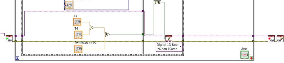
I'm controlling the circulation pumps of the water with relay ni9481 based on temperature differences. It works fine, but I also want to stop the pumps working when I press the button on the front panel. Now, if I press stop when the light on the relay is ACTIVATED it stays on and I have to use MAX to turn it off. How can I set the switch to open the circuit automatically at the end of the race? Thank you.
Just before of you stop and cancel your job (always outside of the loop), just use DAQmx writing to write all FALSE in your DIO. That all goes out and then you disable your task.
-
Hello
I am trying to develop a system to monitor the components on the cards of PCB in the oven, it s essentially has a failure analysis of components such as C, resistors and capacitors.
Here are some of my test system
The test system must monitor the components on the PCB 1 year.
I want to measure the resistances and abilities using a RLC to identify the problem. Failure of the resistance is identified with an open circuit and a failure of the capacitor is identified with a circuit short circuit/open. I have a 420 capacitances to measure and I would like to automate the measurement using multiplexers of NOR.
I got to watch the first ability (C1) 3 minutes (which would be linked to the first input of the multiplexer), followed by second 3 minutes and so on. Once all 420 capacities are monitored, the loop must start from Capacitance C1. I would like to know how to program the switches of the NOR. Could someone please suggest me how to proceed with this. ? Is good enough to automate Labview switches or should I go ahead with the switch management software? Can you please explain in detail because am a beginner in Labview? Forward to your response. Thanks in advance
Hello switcher.
Yes, LabVIEW is an ideal programming environment!
 .
.I suppose you have no switch OR equipment at the present time.
Measurement of the capacitance range are you watching?
What voltage are the plugs at? Looks like it's just a test section, but I guess the capacitors to be held at a constant DC bias? (Otherwise, the test data that you collect is capacitance of the real world).
Without any specific input except the number of capacitors, I recommend 5 multiplexers of PXI-2575 x configured as a 2 son 98 x 1 mux. You can use the PXI-2575 x modules only 3 in mode 1 wire 196 x 1 if your DUJT capacity is sufficient to overcome the parasitic capacitance total of 420 caps (all the negative wires would be linked to the negative contribution of the IGS), but I recommend the approach 2-wire, because it isolates each CAP in a differential measurement.
The PXI-4072 has a function of measure of ability.
With respect to the software, I recommend using NOR-DAQmx switch API, but you can also use the OR-Switch and NI Switch Executive API as well. However, I think that NI Switch Executive is excessive for this application, and it will take a unique session for each switch OR Switch module (OR-Switch is consistent IVI and IVI has no concept of linking several modules).
.. ask away if you have any questions. I'm not "wait I answered them: all in this first response."
-
Digital output is not 5V when connected to a circuit
I have a very simple circuit I want to operate a valve. I have a NI USB 6008 with 12 digital i/o ports, a KF0602D solid state relay, 12V power and a solenoid valve.
The idea behind this circuit is pretty simple: use a digital line of the 6008 to close or open the switch in the KF0602D. With the switch closed, current flows from the power supply through the switch, to the valve and that opens. When the switch opens no current flow and the valve closes.
When I plug my 6008 in the KF0602D, however, my 'high' digital output falls from 5V to 1.73V. It's a problem because my switch requires at least 3V to close. I don't know why the voltage decreases because the relay is supposed to just on 3mA current with an input 5V, wells in the area of the specs listed 6008. What can I do to make this work?
Outputs digital USB-6008 are drain opened with pull-up 4.7 kohm resistors. This will NOT lead your SSR entry requiring > 2 my.
He must reverse the polarity of your control signal. Wire-entrance of the Republic socialist Soviet to the line of the 6008. Wire the + input of the Republic socialist Soviet to + 5 V. Then you have the 8.5 my driving ability to do what you want.
Lynn
-
Reading USB-6210 tension slowly decreases with switch
I am able to output constant 5V to an adapter hung on the wall. The positive wire goes through a switch to the positive terminal AI and the negative wire goes directly to the corresponding terminal negative AI (basically I want the analog voltage to reflect when the switch is on or off). I have the DAQmx configuration for differential configuration. When the switch is activated, it reflects 5V quickly, however when the switch deactivates the voltage goes down very slowly, taking 30 seconds or more to bottom. Also, it does not on 0V, she settled on approximately - 600mV or.
My configuration configuration is incorrect?
Also when I connect a multimeter to the circuit the DAQ steps perfectly, with the tension fall closed when the switch is opened. So maybe the configuration is correct and the introduced impedance is what it takes?
Andrew:
Your train is correct. 6210 has an input impedance of 10Gohms, so, when you open the switch, the factor of the resitance/capacimetres will take much time to bleed pressure down and the entry of data now being an open circuit, it can float just about any level of tension. You could put an arbitrary ristance between terminals of input data acquisition (but not too low). Try something like 10K or 100K ohms.
Alternatively, you can use one of the digital inputs on the 6210 to monitor the switch. Given that supply is 5V, it is compatible for the TTL inputs.
-AK2DM
-
Need to set the switch to the user event
I am creating the simple thing by closing the switch as in image2 light bulb can I achieve using adobe?
The image1 is real state and when I close it (on user event) the switch, the switch status should change and bulb should light up.
When there are still once a user switch event must be like the image1.
Image1
 Image2
Yes, you can create this effect using Flash. You can create two different frameworks, one showing the open circuit and the other showing the closed circuit with the light bulb on the schema within a movieclip. Some event you intend to tell the movieclip to change images based on any framework is now.
It was an approach, but there is a varoiety of ways to do this.
-
Creation of a virtual circuit with LabVIEW
Hello
I am a student in first year engineering on a vacation of the summer research program. Literally just started using LabVIEW.
My request - I can create a virtual circuit and then use LabVIEW for control switches/relay/circuit breakers in the circuit. My University has a microarray and my own research during the holiday season is to make an interface for this grid. The main objective is to control switches etc. using LabVIEW. And so to be a freshman with many prejudices against me (haha) it would be nice to use something virtual rather than something I could break.
See you soon
Then, we must understand what you want to do.
If you want to simulate the whole shebang, you can do it.
You can simulate buses, with expenses and supplies switches and vulnerabilities. It's just math operations.
After 37 seconds, the transformer to the 6-G node fails and draws excessive current, the circuit breaker for bus 6 breaks the circuit OK?
I don't see what good that would do, but you could do it.
If you really want to control the physical microarray, then you must have the interface hardware.
Perhaps you need a digital I/o card, where iron 0 runs on the #6 bit 1 bus power depends on the load, and iron #2 turn on the load of over-current and you have the feeling that the CB tripped looking bit 8, and so on.
Maybe you need an analog output, where you the value of the 130 V supply voltage and set the frequency to 65 Hz instead of 60.
Maybe you need an analog input, where you measure the current at the point the circuit breaker is triggered and measure the voltage of the battery and so on.
There are MIO devices with some of these areas, there are the specialized devices focusing on high performance in one of these areas.
LabVIEW can control all.
It will not be fun. You can't plug the Council, launch LabVIEW and have it do what you want. You need to do some programming. It is much easier than using other languages, but it is not trivial.
Hope that helps.
-
Goal opening on-line evolution of the view in manual mode
I just bought a 135 the opportunity and have noticed on 2 occasions that the aperature will start auto-adjustment in Live View mode, I increase or decrease the exposure. The device always said openness is 2.0 and it always makes the wide-open image... but wiew live will obviously be stopped down. The first time he did it, I turned the camera then next turn, and it has ceased to be. I then cleaned the lens a little contacts with a pencil eraser. The second time, he did it, I twisted the lens and then turn it on again, and he stop doing that. I think so at this point it's a matter of lenses, but I was wondering if anyone has had a similar problem? The camera is a Canon 5 d Mark III. When I press the DOF button it switches open toward the great aperture, but only when it is pressed (as it is supposed to). When I let him go, Live View returns it is stopped down to view, at the bottom left, he always says '2.0 '. Live view should always stay in a wide open aperture, no matter what camera settings, correct?
It's as if the camera is self-adjustment opening to keep the Live view of overexposing / exposure. Y at - it a setting of the camera that I don't know of?
Thank you for reading...
It is the simulation of exposure, not changing opening.
-
authentication open for debugging of the aaa on Powerconnect
Hello
We put in place of the switches to use RADIUS. In order to check if all clients authenticate as we think they do, it would be nice to issue a command as they have in Cisco switches "open authentication". This allows 802. 1 x do its work, but allow the customer through anyway. In this way, you can see if the 802. 1 x has failed or succeeded, without worrying about end users.
Is there a similar function in Dell Powerconnect?
Concerning
Kjetil
I looked through several different options to see if the switch can be manipulated to perform the same action as the open authentication, but I couldn't find a way. I thought that the computer-vlan command would work. But with that VLAN must be different from the authenticated VLAN.
Page 508 of the user's guide has a detailed example that you can follow.
Expand each step you need to take to implement. Then during the hours full no implement and test. Be sure to have a backup of the current configuration.
-
How to map a network switch manually
Hello
I have a Data Center remote I'm trying to draw, without visiting the site and the tracing of cables. Because I can access the table of addresses on each switch, what is the best way to know if button A is connected to the switch B? the switches in my MS are stacked, which complicates things a bit.
For example when I look at my MAC address table, almost all my switches have a MAC by port, port of the channel apart (I think it's a link aggregate port) which shows the MAC addresses belonging to Dell, Cisco and other devices. How can I find out the opening of the canal in which plugs directly? Get a Dell switch or say a Cisco switch?
Thank you
Just in case someone else needs it, I discovered the following invaluable tools:
Use the web browser on each switch to view nieghbors LLDP (real gives of switch ports and can also show the details announced on non Dell kit)
Use the commands 'show deck' and «see the mac»
See the neighbouring ISDP is also useful (depends on the switch)
Open Network Manager was not as smart hoped for example, with the SNMP strings to two directly connected switches, I could not find a way for the NOM give the link real ports -
Switch Cisco Nexus 6004 removes more than 300 bytes IP packets
Hi all
We have a circuit of wave level 3 10 G running between two switches Cisco Nexus 6004. The circuit came online between our two data centers (in the same city) without problem.
When attempting to ping to the remote-end 10G interface, it works very well with packets of 64 bytes. CDP is enabled and that we see the CDP information remote switch. However, if we increase the size of the ping to more than 300 bytes packets, we lose 1 in every 20.
We settings MTU verifed, type of cable of 10G and duplex settings.
Level 3A tested clean and we will move forward with more testing.
Any ideas on the problem? We feel the carrier out and end to test with their testers. But so far, the circuit's own test. I was not sure if it is something related to Cisco. I am at a loss at the moment.
Thank you.
Mike
Hi Mike,.
There is nothing wrong with your switches or circuit. NEXUS devices have a default COPP on the control plan that limit the size and the amount of traffic that must be the CPU process.
HTH
-
Export button on the Advanced sub-region Switcher does not fetch data in excel
Hi all
I have an urgent need.
The question is:
I have a Swich area, based on its attribute VO, Case1-> makes Advanced Table1, CAS2-> make advanced table2
Now, I have exportButton in advance Table1 and Table2 advance.
After querying data on the page, by clicking the export button set to these tables in advance (in the region of switcher), open the excel file, but with no data in it.
I looked and I saw in the guide of the OFA switcher column requires setting 'Export the view attribute' but my problem isn't switch column.
My question is exportButton not work on advanced table that is part of the container case region switch, excel opens without any data in it (advanced table VO has the data displayed on the page).
Please help with your valuable suggestions.
Thank you
Sree
Hi Mary,
Visit this link:
Blog on Oracle of Mukul technology: implementation of export button features programmatically
Sushant-
-
NEITHER 9481: Why dose the relay turn off all channels once every time when the vi is executed?
Hello all, I use cRIO 9025 and NI 9481 to develop a program. The relay is used as switches. I designed it, is that when I run the vi, the channels of the relay are all on. When the port of entry of the digital input/output module gives a signal to the relay, the relay channels is disabled. However, whenever I run the vi, the relay is disabled once and then trund once again. May I ask why is this happenning? I guess that's because the default state of the relay is disabled. Is there a way to fix this?
Thank you very much!!
All the relay modules are like that and there is nothing that can be done as far as I know. Electromagnetic relay are generally loaded spring and holding (switch closed) by a voltage sent to the relay. They will turn off when restart you on the relay controls. You can set the State of the relay on real as the first thing when you start your VI, but beyond that you would have to solve your electrical problem, control switching relay at a constant voltage during the startup of the program. However, in most cases it would be risky and unreliable. However, there are many different types of relay and you did not specify that you are using.
See basic operation section, section of this article to read on how to relay themselves by default to the State of open circuit:


Maybe you are looking for
-
Exchange records between A10 and 2410
Do Satellites - the 2410 and the A10 - and would like to know if I can swap the drives? (1) so the first thing is confirm compatibility? (2) someone at - it links to some good step by step instructions how to do this? (3) if not, would you recommend
-
1.0.3 phone says unable to connect
I tried this now for two days in different locations and I get the message UNABLE TO CONNECT, TRY LATER. I have a signal strong WiFi, and the phone did the first update a few days after I had immediately. I'm doing something wrong?
-
screen white/rewrites in a loop after install Win 10 to XPS8500
XPS8500 with the fully functional installation of Windows 10. Tried to install the upgrade from the W10. now the screen blanks/rewrites loop. Burst out of the loop, but cannot restore to the previous version. Init ok, ok the backup data, stops on the
-
Need a recommendation for a second firewall router
I have currently a second router connected to the LAN port of the #1 router/WiFi in order to create a firewall between the Local area network of my #1 WiFi router and a PC which is connected by a cable Cat5 to the second router. This second router ha
-
Causing the Blue Screen of Death (IRQL_NOT_LESS_OR_EQUAL) wireless adapter
I had a Linksys WUSB600N Wireless-N USB adapter (dual band ver. 2) for a period of several months now, no problem, running on Windows 7 Pro 32-bit. So without any hardware or software changes (to my knowledge), have the adapter plugged during initia