Coordinates of rotation textframe
With the help of horizontal and vertical itemtransform distance and point of path tables, I can find the coordinates of the text frame (x 1, y1), (x 2, y2), (x 3, y3), (x 4, y4). If the textframe is turned then transform element values can be changed, but points of path table values are the same. I can find the angle of rotation of the matrix [cos (θ) sin (θ) - sin (θ) cos (θ) 0 0], but I couldn't get the exact coordinates of rotated textframe. Managers of related texts are given below.
Normal text block
< TextFrame Self = 'u136' ParentStory = 'u124"ItemTransform =" 1 0 0 1 101.72727272727272 - 349.41818181818184 ">
Properties of <>
< PathGeometry >
< GeometryPathType PathOpen = "false" >
< PathPointArray >
"< PathPointType anchor =" "- 101.72727272727272 - 46.581818181818164" LeftDirection = "- 101.72727272727272 - 46.581818181818164" run = "- 101.72727272727272 - 46.581818181818164" / >
"< PathPointType anchor =" "- 101.72727272727272 - 0.3272727272727103" LeftDirection = "- 101.72727272727272 - 0.3272727272727103" run = "- 101.72727272727272 - 0.3272727272727103" / >
< PathPointType anchor = "115.9090909090909 - 0.3272727272727103" LeftDirection = "115.9090909090909 - 0.3272727272727103" run = "115.9090909090909 - 0.3272727272727103" / >
< PathPointType anchor = "115.9090909090909 - 46.581818181818164" LeftDirection = "115.9090909090909 - 46.581818181818164" run = "115.9090909090909 - 46.581818181818164" / >
< / PathPointArray >
< / GeometryPathType >
< / PathGeometry >
< / properties >
< / TextFrame >
TextFrame rotated
< TextFrame Self = 'u136' ParentStory = 'u124"ItemTransform =" 0 1 0-1 320.3805483338268 - 125.07900895050204 ">
Properties of <>
< PathGeometry >
< GeometryPathType PathOpen = "false" >
< PathPointArray >
"< PathPointType anchor =" "- 101.72727272727272 - 46.581818181818164" LeftDirection = "- 101.72727272727272 - 46.581818181818164" run = "- 101.72727272727272 - 46.581818181818164" / >
"< PathPointType anchor =" "- 101.72727272727272 - 0.3272727272727103" LeftDirection = "- 101.72727272727272 - 0.3272727272727103" run = "- 101.72727272727272 - 0.3272727272727103" / >
< PathPointType anchor = "115.9090909090909 - 0.3272727272727103" LeftDirection = "115.9090909090909 - 0.3272727272727103" run = "115.9090909090909 - 0.3272727272727103" / >
< PathPointType anchor = "115.9090909090909 - 46.581818181818164" LeftDirection = "115.9090909090909 - 46.581818181818164" run = "115.9090909090909 - 46.581818181818164" / >
< / PathPointArray >
< / GeometryPathType >
< / PathGeometry >
< / properties >
< / TextFrame >
Can someone help me know the cordinates of rotation textframe.
Thanks in advance.
I suspect that you will do better to ask here: http://forums.adobe.com/community/indesign/indesign_sdk
Tags: InDesign
Similar Questions
-
coordinates of rotation problem
Hello world
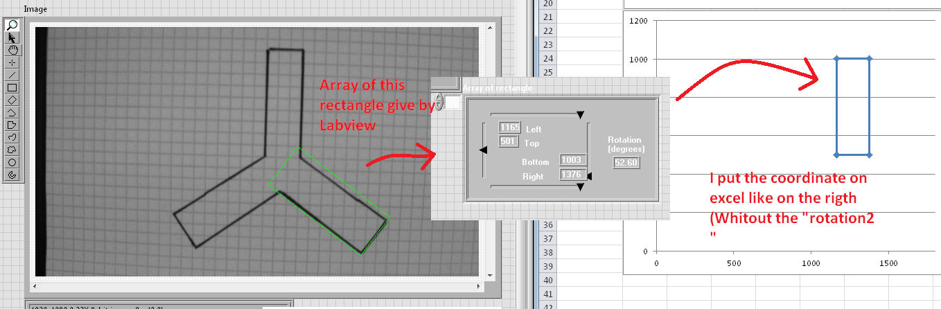
I'll try to be clear, but I just have a problem with the coordinate on a rectangle of rotation.
So, first of all, I have this data, and when I put in Excel I a rectangle to the right.
SO now I know I need to change the data in the rotation, that's what I did.
It worked great, I tried with graphic and to change the degree of rotation, it was perfect, I had good rotated rectangle.
My next and last stop was just to put the coordinate to Excel and to reproduce the same rectangle on a chart in Excel.
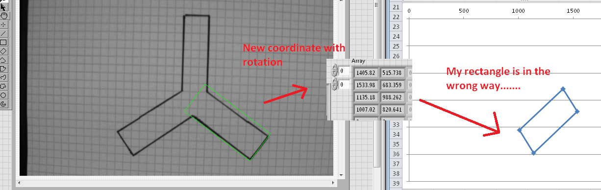
And that is where I met the problem.I have no idea why, and I don't see what to change to fix that...
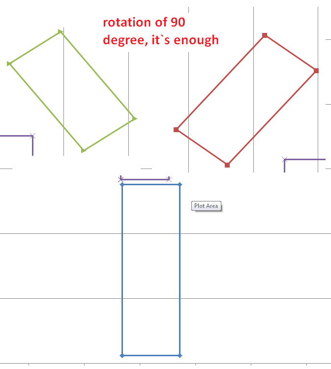
I now just a rotation of 90 degrees, it is sufficient to correct the position but where can change something?
If somenody know something or have the solution, you are welcome.
Sorry about that big post but I think is more clear with the image that more text.
Thanks again for your answers (in advance)
Maxim
Direction of rotation?
In Excel, it looks like a postive rotation causes rotation in the clockwise direction.
I did not dig your math, but in many programs (such as Autocad), a rotation angle positive hour meter follows the right hand rule. Where 0 is the + axis X and a line there turns towards the + Y axis with a + angle.
-
When I rotate a picture how the new cordinates of the image.
This image is rotated around 0.0, but what is the coordinates of the other corners now he turned bone?img1.rotation = _angle;
May be better to round the number:
private function rotatedPoint(originalPoint:Point, rotation:Number):Point { var p:Point = new Point(originalPoint.x*Math.cos(rotation) - originalPoint.y*Math.sin(rotation), originalPoint.x*Math.sin(rotation) + originalPoint.y*Math.cos(rotation)); p.x = Math.round(p.x*100)/100; p.y = Math.round(p.y*100)/100; return p; } -
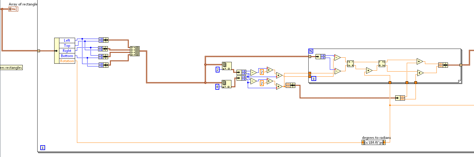
How coordinate values to change the rotation?
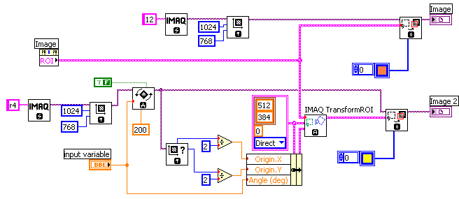
I need to know how the pixels coordinates change when they are turned by a certain angle.
Or suggest a few VI which will give the new values of coordinates after rotation...
Pls answer
Recorded in LV 8.2. Screenshot attached.
Andrey.
-
Problem to claim a VI help script DIADEM
I get the "LabVIEW: the VI is not executable...» "error message when you try to load a VI using DIAdem scripts. However, the VI loads and runs fine when it runs from labview. I've isolated the problem to a sub VI called "Cartesian coordinates 3D Rotation (branch) VI. This VI is packed with labview and is in the "palette geometry of screws. If I remove this subroutine VI, then the VI I want to call is in charge within the tiara. Any idea to do this job properly would be appreciated.
Thank you.
Hi PRinOR,
You do 2 things just right. You must create a source distribution that includes all the SubVIs, even those of vi.lib, and you must match the LVRuntime.Init version exactly with the LV of the VI version that you load. I noticed in your VBScript post that you do not specifically set the LV version, but take the default value. Have you managed to call a simple VI of tiara which has no SubVIs, like a VI that adds 2 numbers?
Brad Turpin
Tiara Product Support Engineer
National Instruments -
rotation of 2D Cartesian coordinates
Running lv 8.5, am I misunderstood how this vi? I entered the vi the following values
x: 1
y: - 1
Theta: pi/2
and the result I get is
x:-1
y: - 1
It seems that it turns the wrong way!
In addition, see here:
http://zone.NI.com/reference/en-XX/help/371361F-01/GMATH/2d_cartesian_coordinate_rotation/
Where the indicated rotation matrix is not the same as that shown in other sources, such as:
http://en.Wikipedia.org/wiki/Rotation_matrix
http://MathWorld.Wolfram.com/RotationMatrix.html
I can't believe no one else has encountered this problem also, what Miss me?
You seem to miss the difference between rotation one point in a fixed PIN and rotate the coordinate system. The sign of the angle is different in both cases. This VI does exactly what the name implies, rotate the coordinate system and the results are exactly what you should expect. Mathematica, among others, guess you turn to a point in a fixed coordinate system, where the difference.
-
How to get the values of coordinates for a rotated rectangle / polygon?
For a rotated rectangle or polygon (no rotation) coordinate values that I can extract are the visibleBounds or geometricBounds. But I want to access the exact coordinate values for the summits of the image.

There in AppleScript:
Tell application "Adobe InDesign CC 2014"
mypathpoints the full path of the channel 1 of the selection value
-Returns {{1.533492951824, 4.286597905696}, {3.125, 7.11}, {5.486507048176, 6.353402094304}, {4.026786834026, 3.150338420818}}
tell the end
So js you get the first path of the rectangle and then get entirePath, which returns a list of x, y coordinates of the four corners.
-
How can I get the coordinates of the using block (TextFrame) text me please!
MyApp as new Illustrator.Application Dim
As Illustrator.Document Dim MyDoc
myDoc = myApp.ActiveDocument
Dim textRef = myDoc.TextFrames.Add
For each ArtPageItems in myDoc.PageItems
If TypeName (ArtPageItems) = "TextFrame" Then"=It is necessary to get the coordinates of the text block and to get closer to the subject (ie the text)="
On the other
End If
Nextfor details of do
If TypeName (ArtPageItems) = "TextFrame" Then
x = ArtPageItems.Left
y = ArtPageItems.Top
On the other
-
Get the correct coordinates for a rotated image
Hi all
I'm trying to get the four coordinates (PMPoint) of a frame of the rotated image.
PGeometry InterfacePtr < IGeometry > (itemList.GetRef (iCOUNT), IID_IGEOMETRY);
PMMatrix matrix =: InnerToParentMatrix (pGeometry);
PMRect rPageItemBoxRect = pGeometry-> GetStrokeBoundingBox (matrix);When I use LeftTop() on rPageItemBoxRect, I expected to get the true X & Y values at this point are as visible in the palette information.
The LeftTop(). X() is ok, but the LeftTop(). Y() is not the value of Y at this time. It's the highest Y of the frame which is in fact the value of Y for the corner of RightTop.
Similarly, all the values that I receive are false.
The X() gives value to the far left of the image for the LeftTop() and the LeftBottom(), when they are different from the rotated image.
And the X() gives the value at the right for the framework for the RightTop() and the RighBottom(),
Y() give value to the foreground of the frame for LeftTop() and RightTop() and so on.How can I get the coordinates of the actual area and not to the coordinates of the bounding box, so that I get the good X, the values of Y for the four corners of my frame rotated as I can see them on the palette information.
Kind regards
Jasmine ShaikhHi Jasmine,.
You can use the interface IPathGeometry of the framework.
Markus
-
How to get the coordinates of "pathPoints" of a textFrameItem?
Hi all
Yes, I know that textFrameItems have pathPoints but...
How can I get the x coordinates of the corners of a textFrameItem of rotation.
I know I can get the angle of rotation of asin (myTextFrameItem.matrix.mValueA) etc.
My guess would be that one should be able to use the mValueTX and mValueTY to help, but these values are very confusing and change dramatically on the application even a small rotation.
If anyone has some preference mathematically based ideas and not API base, please let me know.
It's very late by me now and I think I must be missing what is obvious, I think that such a function must have been made.
Thank you
Trevor
PS Would be also appreciated a solution to the problem even in InDesign

Hi all
I didn't try the method DOM I knew the mathematical method.
I don't give great results if a shear has been applied, but that doesn't bother me that I do not apply the shears
I received contact details-box-find http://stackoverflow.com/questions/9971230/calculate-rotated-rectangle-size-from-known-bou a useful formula
y = (1 / (Math.cos (a) * Math.cos (a) - Math.sin (a) * Math.sin (a))) * (-w * Math.sin (a) + h * Math.cos (a));
where y is the height of the inner when box no rotation is applied on it and a is the angle of rotation and w is the width.
I had found for me a different formula but got stuck when moving to the rotation out of the 90 degree range, that is to say 1 degree or 91 degrees.
The same problem occurred with this method to fix a fact of what follows.
a RAD = ((360 + degs (a)) 90%);
I did the temporary to degrees conversion as I remember problems with Mod enforcement by a fraction, I think that Ariel was a thread on this in the indesign forum.
Here are the results of the script


// draw a text box and rotate it before running the script
// By Trevor www.creative-scripts.com (sorry still not too much there)
// https://forums.adobe.com/message/7678561#7678561
// With a little bit of help from http://stackoverflow.com/questions/9971230/calculate-rotated-rectangle-size-from-known-bounding-box-coordinates
function main () {

var doc = app.documents.length && app.activeDocument,
    itext = doc && doc.textFrames[0];
if (!itext) {
    alert ("Sorry mate,\nI need a document with a textFrameItem on it or there's not much for me to do");
    return "twit";
}
var gb = itext.geometricBounds,
    imatrix = itext.matrix,
    p1X, p1Y, p2X, p2Y, p3X, p3Y, p4X, p4Y,
    a, h, w, x, y, hyp, op, adj,
    noColor = new NoColor(),
    rgbColor = new RGBColor(),
    newShape = doc.pathItems.add(),
    rect;
;

// Do the maths

a = Math.atan2 (imatrix.mValueB, imatrix.mValueA); // get the angle of the textFrameItem
a = rads ((360 + degs(a)) % 90); // make sure it's positive otherwise the result will get messed up
w = gb[2] - gb[0]; // Width of outer enclosing box
h = gb[1] - gb[3]; // Height of outer enclosing box
/* x = (1/(Math.cos(a) * Math.cos(a) - Math.sin(a) * Math.sin(a))) * (w * Math.cos(a) - h * Math.sin(a)); // Width of inner enclosed box, this is not needed for this script */
y = (1/(Math.cos(a) * Math.cos(a)- Math.sin(a) * Math.sin(a))) * (- w * Math.sin(a) + h * Math.cos(a)); // Height of inner enclosed box
op = Math.sin(a) * y; // this is the x coordinate offset
adj = Math.cos(a) * y; // this is the y coordinate offset

// calculate the points of the inner enclosed box
p1X = gb[0] + op; // left bottom
p1Y = gb[3];
p2X = gb[0]; // left top
p2Y = gb[3] + adj;
p3X = gb[2] - op; // right top
p3Y = gb[1];
p4X = gb[2]; // right bottom
p4Y = gb[1] - adj;

// Draw outer box
rgbColor.blue = 255;
rect = doc.pathItems.rectangle(gb[1], gb[0], gb[2]-gb[0], Math.abs(gb[3]-gb[1]) );
rect.fillColor = noColor;
rect.strokeColor = rgbColor;

// Draw inner box
newShape.setEntirePath([[p1X, p1Y], [p2X, p2Y], [p3X, p3Y], [p4X, p4Y], [p1X, p1Y]]);
rgbColor.red = 255;
newShape.strokeColor = rgbColor;
newShape.fillColor = noColor;

// Helper functions
function rads (x) {return x * (Math.PI / 180);}
function degs (x) {return x * (180 / (Math.PI));}

}
main()
Hi Uwe,
It was late, but I don't know how I missed the path object. Age!
A good thing I didn't post on the InDesign forum, at least here, I can wait less snickering for a such silent over look that I went back to the InDesign forum
Either way thanks to you two, best regards,.
Trevor
-
The attached code giving the entries for a single cordinate keeping other cordinates == 0. everything is ok.
But if ikeep some x = 10 and if I'm variant y image arrived at the starting position. What could be the problem
First of all, you don't want to probably use a time-out, but rather change it to an event of "Change value" which checks X, Y and Y. It will be much more efficient (from now on, even if nothing is changed, you recalculate the image every 2 ms...). See attached the amendment.
Then, what do you do? As you probably know, the 3D rotations are not commutative (for example a rotation around X, followed by a rotation around is not the same thing as the two operations carried out in the reverse order). Your code currently indicate the axis of rotation (the cluster of X, Y, Z coordinates) passing ANGLES. It's probably not what you want to do. This cluster specifies the axis VECTOR. The other setting, i.e. the angle must be controlled by a separate parameter. Therefore, if you want to rotate either around the axis X, Y or Z at a specific angle, you probably want to do what I did on the attached amended 2.
-
Rotate an image after clicking twice on benchmarks in the photo
Hello community!
I am looking for a solution to rotate an image by clicking on the two reference points on the image. The two pairs of coordinates of the mouse clicking on can give me the angle of rotation with a simple geometry. After this, I turn the image with the calculated angle.
My problem is: How can I get these two pairs of coordinates? I wanted to do it with a simple MatlabScript ' entry: path... imread (path)... imshow... ginput (2)... calculating... out: angle. Apparently imshow doesn't in Labview

I already have the mouse event to the bottom, but I don't know how I can do Labview let me click EXACTLY and ONLY twice on my photo and store contact information.
Any of you have a glue / trick how to do this?
Best,
Olivier
(LabView started 2 weeks)
Added version LV2012.
Ahhhhh, in the event data node it is already a property for details.
-
How image rotation and displacement by using different origins
Hello
I use LabVIEW 8.5 and 8.5 of Vision.
I need to rotate, scale, and move a 2D image regarding one aspect of the image. I use IMAQ turn and shift, but I don't know what is the point of reference or originally used in this function. The coordinates of the image is very important in my application because I need these details to complete the recording of the image.My question is as below:
(1) the origin (0,0) of an image is located in the upper left corner, can I change it to the center of the image?
(2) how can I specified a certain point (coordinated) as a reference for the rotation and scale?
Your help is very appreciated. Thank you.
Hello
Thanks for the idea, I'll try it soon.
Best wishes
-
Effectiveness of the Cartesian to spherical coordinate of the conversion
I use a VI in the LV 2014 distribution called ".vi NI_AALPro.lvlib:3D Conversion of coordinates (scalar)". It uses DBL inputs and outputs and has several functions of table build in it as a library function call. I need to make a massive number of Cartesian to spherical conversions with SGL values, and so I would like to re - write this VI using LV primitives most efficiant manner.
The calculation seems to be pretty simple, and I've attached a VI that does this. However, there is a problem with the calculation of the polar angle. From what I've read online, this is just arctan (y / x), but I get incorrect values when x is negative (but not when there is negative).
From what I've read on the site of Wolfram, "the inverse tangent must be properly set to the right quadrant of (x / y) into account." I searched online for more details on the calculation, but I'm lost. Any trig works there who can help me?
Definitions are extremely important in the definition of coordinate systems. You include with your VI Cart_to_Sph documents of many errors and inconsistencies.
This is a convention that I use and which seems to be acceptance quite wide (I'm not sure that's the convention of Wolfram, however).
Let X, Y and Z is a right coordinate system. That P is a point whose X, Y, Z coordinates we know. Define a system of spherical polar coordinates (SSC) as follows:
- Project of a line from the origin to P.
- RADIUS (rho) - length of the line from the origin to P.
- The line of the project on the X - Y plane.
- Azimuth (theta) - measured Angle to the left of the x-axis for this proposed line. By convention, theta varies less pi (radians), pi.
- Polar angle (phi) - the angle between the axis Z (or 'pole') and the line from the origin to P. By convention, including phi between 0 and pi.
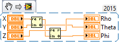
Under this system of coordinates, the following code (very similar to Altenbach, which uses a slightly different coordinate system) cards X, Y, Z in Rho, Theta, Phi:
We will check certain quantities of 'known '. Start with the x-axis of the unit, [1, 0, 0]. This clearly has length, Rho = 1. The X axis lies in the XY, so the angle between the latter and the Z axis is 90 °, Phi should be pi/2. Finally, the projection of the X axis in the XY plane is located along the X axis, so the angle between the two axes of X is 0, so Theta should be 0. The first Re / Im polar will give 1, Theta Yes 0 = 0. The second will give 1, pi/2, and Yes 1 = Rho and Phi = pi/2.
How about unit Z, [0, 0, 1]? Again, the length, Rho, is 1. Technically, since the z plans on the origin, the Azimuthal angle cannot be properly defined (the X coordinates and are 0), so we'll do a loophole 'math' and just say that it is zero. The polar angle is easy - the angle between the Z axis and the pole, the Z axis is 0, so Phi = 0. Now "do the math". Put [0, 0] in the first Re / Im polar gives [0, 0], so theta = 0. The second d / Im to polar takes [1, 0] [1, 0], Rho Yes = 1 and Phi = 0.
It is easy to show (in particular by the coding of this place and put in test of numbers) that negative quantities are working properly. Rho is always non-negative, Phi is always in the range 0... PI and theta of pi-pi, with the sign depends on the sign of Y (as it should).
Bob 'just do the math' Schor
PS - If you think this is fun, just try 3D rotation matrices...
-
How to set the preview of the camera when the screen is rotated?
I have a ForeignWindowControl with the control of the camera and when I turn the device, the user interface controls on the screen are properly redrawn but the preview camera does not turn properly. a little weird.
What I need to adjust the size of ForeignWindowControl you turn so full so how?
not serious. the reference to coordinate for display has been turned, so you must rotate your viewfinder window handle of window screen. who should sort. I guess you see a compressed laterally viewfinder.


Maybe you are looking for
-
ReadyNAS BusinessPro (6310) update to OS 6 stuck at startup to 98%
Subject pretty much said it all. It is stuck at '98% bootstrap' for more than eight hours. I read other messages saying that the upgrade was successful. For those who have had success, how long did take? Thank you.
-
How to install EPSON STYLUS TX135 PRINTER
How to install EPSON STYLUS TX135 PRINTER Concerning
-
Contacts for editing and synchronization to blackBerry Smartphones
Hi, one made an absolute mess of sync my contacts with Outlook. First I had to change the simm card then I downloaded contacts from my old sim to my BB until the Sim Card has been cancelled. I'm now working with the new SIM card. I connected up to B
-
Applications pre-loaded blackBerry Smartphones
Hey people! I have a quick and a little ridiculous for you. Is there anyway I could get a list of applications preloaded on the 8220? I googled around but get only offers to download new content. Thanks in advance! Bmobile
-
Hey guys,.Pretty novice at the Premier Pro (am a 3D viewer, not a composer/editor), but am very good with the basics.I have made a series of images for animation, including a ZDepth pass and I was wondering if it is possible (without third-party plug